
Water tank overflow is a common problem that leads to water wastage, yet it's surprising that many households don't even consider it a concern. Though there are many solutions for it, like ball valves that automatically cut the flow of water when a certain level is reached, as an electronic engineer, I prefer a solution that includes sensors and automation. So, in this tutorial, we are going to interface a water level sensor with Arduino to measure the water level, and in the process, we will let you know the details about this sensor and its working. So, without further ado, let's get right into it. This water level sensor Arduino tutorial presents an electronic approach using sensors and automation. In this comprehensive guide, you'll learn how to build a complete water level sensor project by interfacing a water detection sensor with Arduino. We'll cover the water level sensor Arduino code, circuit diagram, and step-by-step instructions to create a functional Arduino water level detector system. Whether you're building a simple water depth sensor Arduino project or an advanced water tank monitoring system, this tutorial provides everything you need.
Table of Contents
Water Level Sensor Pinout
The working principle of the water level sensor module is very similar to that of a Rain Sensor.
The water level sensor has three pins, runs on 5V power, and gives out the data in analog format. The pinout of the water level sensor is given below:
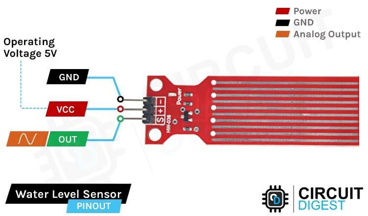
The module has just three pins, which makes wiring it to your Arduino water level sensor project straightforward.
VCC is the power supply pin of the Rain Detection Sensor that can be connected to 5V of the supply.
GND is the ground pin of the board, and it should be connected to the ground pin of the Arduino.
OUT is the Analog output pin of the board that will give us an analog signal between VCC and ground.
| Pin | Label | Connect To (Arduino UNO) | Description |
| 1 | VCC | 5V | Power supply (3–5V); use 5V for maximum sensitivity |
| 2 | GND | GND | Common ground reference |
| 3 | OUT (S) | A0 (Analog pin) | Analog output: 0 V (dry) → ~3.85 V (fully submerged) |
Water Level Sensor Specifications
Here is a quick-reference specifications table for the resistive water level sensor module used in this Arduino water level sensor project:
| Parameter | Value |
| Operating Voltage | 3V – 5V DC |
| Current Consumption | 3 mA – 41 mA |
| Output Voltage Range | 0 V – 3.85 V (Analog) |
| Output Type | Analog (can also drive a digital threshold comparator) |
| Water Detection Area | 40 mm (H) × 16 mm (W) |
| Operating Humidity | 10% – 90% RH |
| Working Temperature | −30°C to +50°C |
| Interface | 3-pin (VCC, GND, OUT/S) |
It is suggested not to operate the sensor with more than 5V, as higher voltage increases current consumption, which also proportionally increases the act of electrolysis in the liquid medium and may result in changing some characteristics of that liquid. One thing to note is that the output voltage will not be constant for a particular level of water over time due to the process of electrolysis, but as per observation, it is quite stable in water that is in motion.
Components Required for Water Level Sensor Arduino Project
| Component | Quantity |
|---|---|
| Arduino UNO Board | 1 |
| Water Level Sensor Module | 1 |
| LED (5mm) | 1-3 |
| Resistor (220Ω) | 1-3 |
| Breadboard | 1 |
| Jumper Wires | As needed |
| USB Cable (for Arduino) | 1 |
How Does a Water Level Sensor Work with Arduino?
The working of the water level sensor Arduino is pretty simple and easy to understand. The PCB is made out of long conductive plates. When the water reaches a certain level, the resistivity between the two plates changes, which is responsible for the variable output voltage.
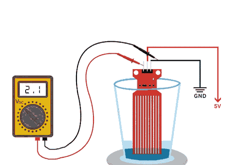
The above GIFs show the working of the water level sensor in action. As you can see, when the drop of water falls inside the glass, the water level rises, and the voltage on the output pin also rises. This change in voltage output happens because of the sensor’s water detection portion on the PCB, which is made out of 10 conducting plates. Five of these plates are power tracks, and the other five are sensor tracks, causing the resistance between them to change.
If you plot the change in water level and output voltage as a graph, you will notice that the graph looks parabolic and exponential. The working principle of this water detection sensor for Arduino is elegantly simple. The PCB features conductive traces arranged in an interdigitated pattern. When building your water level sensor project, understanding this mechanism is crucial. This Arduino water level detector setup has five traces going to VCC through a 100Ω resistor, and five interleave traces go to the base of an NPN transistor. As a water depth sensor, it provides real-time analog feedback - the deeper the immersion, the less resistance and the higher the output voltage. This water level monitoring application is great for many water level control situations, from basic water overflow to complicated IOT systems.
Water Level Sensor Module – Parts
This sensor is very simple, so it can be made with very few parts. This sensor produces the water level and outputs the data in an analog format. The parts marking of the sensor is shown below.
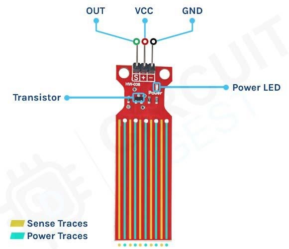
The sensor module has three pins, two of which are power pins and needs to be connected to the 5V and ground pins of the Arduino. As you can see in the above picture, the module has a single power LED that turns on when power is applied to the board. Other than that, we also have a transistor and a bunch of resistors that, in total, make the water level sensor module.
Circuit Diagram for Water Level Sensor Module
The Schematic Diagram of the Water Level Sensor is shown below, and as you can see, it's pretty simple to understand.

In the schematic, the collector of the transistor is connected to the supply voltage of 5V, and the emitter is connected to the ground with a 100-ohm resistor. In the module, a set of 5 conducting plates is connected with the VCC in series with a 100 Ohms resistor and the other 5 sets are connected to the base of the NPN transistor. Now, when the water touches these conducting palates, currents start flowing from the 5V supply to the base of the transistor, and the transistor turns on. The more submerged the sensor is, the more output voltage it will generate.
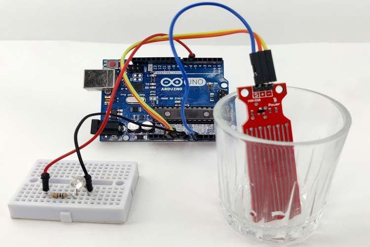
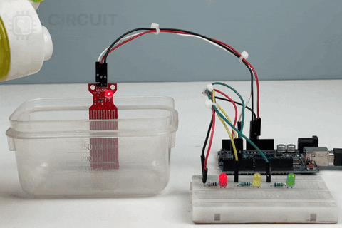
Arduino Water Level Sensor Circuit – Connection Diagram
Now that we completely understand how the water level sensor works, we can connect all the required wires to the Arduino UNO board, and in this section of the article, we will discuss just that!
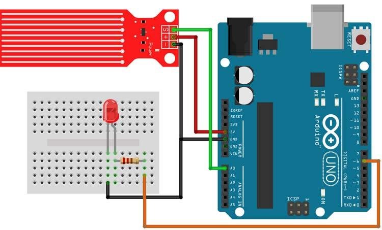
Arduino Water Level Sensor Circuit – Connection Diagram
The wiring for the water sensor Arduino setup is minimal. Follow the connection table below, then refer to the diagram image for visual confirmation.
| Water Level Sensor Pin | Arduino UNO Pin | Notes |
| VCC | 5V | Do not exceed 5V to prevent electrolysis damage |
| GND | GND | Common ground |
| OUT (S) | A0 | Analog input; ADC reads 0–1023 |
| – | D6 (PWM) | LED output (through 220Ω resistor to LED anode) |
In the above figure, the connection diagram for the water level sensor with Arduino is shown. We have connected an LED to the PWM pin 6 of the Arduino board, and the analog output pin of the sensor is connected to the A0 pin. The ground pin is common between the module and the LED, and the VCC is taken from the 5V pin of the Arduino. We will program the Arduino so that the brightness of the LED will change depending on the water level sensed by the sensor.
Water Level Sensor Arduino Code – Explanation
The Arduino water level sensor code is explained below. The code is very simple and easy to understand. We just have to read the analog data out of the sensor, and we can approximate the average water level with the ADC of the Arduino.
We initialize our code by declaring two macros, the first one is for the LED, where we will connect an LED, and the second one is the sensorPin through which we are reading the data coming out of the sensor.
// Sensor pins pin D6 LED output, pin A0 analog Input
#define ledPin 6
#define sensorPin A0
Next, we have our setup() function. In the setup function, we initialise the serial with 9600 baud. We also set the ledPin as output, and make the pin LOW. This way, the pin will not float and turn the LED on.
void setup() {
  Serial.begin(9600);
  pinMode(ledPin, OUTPUT);
  digitalWrite(ledPin, LOW);
}
Next, we have our loop function; in the loop function, we read the sensor pin and store it in a local variable named sensorValue. Then, we defined an if condition in which we check if the incoming value from the sensor is greater than 570. If so, we map the value with the help of the built-in map function of the Arduino, and finally, we generate the PWM signal with the help of the analogWrite function; the final serial. print function is there for debugging.
void loop() {
  int sensorValue = analogRead(sensorPin);
  if (sensorValue > 570)  {
    int outputValue = map(sensorValue, 570, 800, 0, 255);
    Serial.println(outputValue);
    analogWrite(ledPin, outputValue); // generate PWM signal
  }
}
Working of the Arduino Water Level Sensor - Single LED Output
The GIF below shows the Water Level Sensor working. At first, you can see that the LED on the breadboard is off, but when we put some water on the glass, the brightness of the LED starts to increase, and when the water in the glass is full, the LED glows at full brightness.
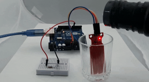
One problem we have encountered while working with this sensor is that the bottom portion of the sensor is very sensitive, while the top portion is not that sensitive. If the water level crosses the bottom portion, the sensitivity almost goes to maximum, and it saturates.
Bonus Example:
Above, we made a simple demo of the working of the Water Level Sensor using an LED as output. Now we will add 3 LEDs showing 3 stages of the Water level as Low, Medium, and High, respectively. First, let's discuss the Circuit Diagram.
Arduino Water Level Sensor with 3 LEDs as output – Circuit Diagram
Below you can see the circuit diagram of the Water Level Sensor Circuit along with three LEDs for showing the Demonstration.
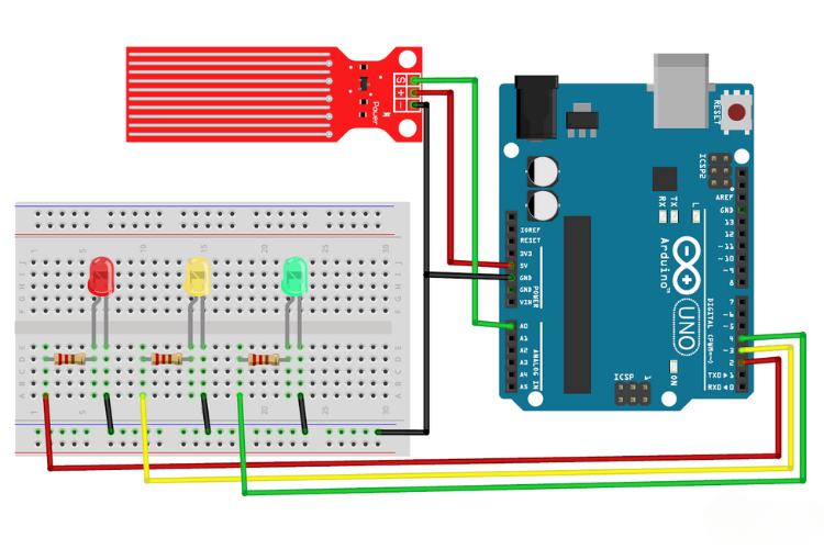
In this circuit, an extra two LEDs were connected; they are the same as in the previous demonstration with a single LED. Following, we can go to the code explanation for this demo.
Next, let's see the Coding Part.
Complete Water Level Sensor Arduino Code with Explanation
The water level sensor Arduino code below reads the analog output of the sensor and drives LED brightness using PWM. The complete code is intentionally simple so beginners can adapt it easily.
#define lowOutput  2
#define mediumOutput  3
#define highOutput  4
Next Comes the Void Loop Section. Here, the Analog DataFrom sensorPin is read and passed to the if-else statements. The values 280, 564 & 640 are found by the trial and error method.
void loop() {
  int sensorValue = analogRead(sensorPin);
  if (280 > sensorValue) {
    digitalWrite(lowOutput, HIGH);
    digitalWrite(highOutput, LOW);
    digitalWrite(mediumOutput, LOW);
  }  else if (564 > sensorValue) {
    digitalWrite(mediumOutput, HIGH);
    digitalWrite(highOutput, LOW);
    digitalWrite(lowOutput, LOW);
  } else if (640 > sensorValue) {
    digitalWrite(highOutput, HIGH);
    digitalWrite(mediumOutput, LOW);
    digitalWrite(lowOutput, LOW);
  } else {
    digitalWrite(highOutput, LOW);
    digitalWrite(mediumOutput, LOW);
    digitalWrite(lowOutput, LOW);
  }
  delay(100);
}
You can find your own by verifying the sensor with you. It's very simple to follow the steps below.
Open the file AnalogReadSerial, which you can find in “File -> Examples -> 01. Basics -> AnalogReadSerial“.
Connect the sensor with Arduino and read the data output via the serial Monitor.
For the 3 states of the water level, note the respective output ADC values. And you can use that in the present Code.
While taking the readings, you might notice that the output won't be linear; actually, it will be an exponential curve when plotted in a map.
This water level sensor Arduino code demonstrates how to build a functional water level detector system. The code reads analog sensor data and controls LED brightness based on detected water depth, making it perfect for beginners learning Arduino water sensing projects.
ADC Output vs. Water Level – Non-Linear Curve
The following Arduino water level sensor code provides the foundation for your water detection project:
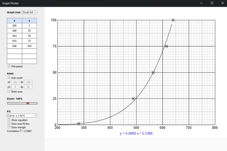
In the above graph, X represents the output value of the ADC, and Y represents the respective level of the water. So, you can clearly see that it was an exponential curve. And if you wonder about the software I used, it is Graph Plotter, which is available in the Microsoft Store. You can use whatever software, and the result will be the same.
So, the if-else statements are self-explanatory. For the set value, the Defined LED will light up, stating the water level.
Next, let's move to the working demonstration.
Working of the Arduino Water Level Sensor with 3 LEDs as Output
Now, let us move to the real-world working demonstration of the 3 LED Output Water Level Indication Project. Here, instead of a single LED, 3 LEDs were deployed to perfectly indicate the level of the Water in the Container.
Pros and Cons of Using a Water Level Sensor:
You can find more about this sensor once you experiment by yourself. The pros and cons below are based on our observations while doing multiple experiments with this water level sensor.
Pros:
This sensor is very simple to integrate with any microcontroller to detect the presence of liquid. It can interface with both analog and digital input pins. It is inexpensive compared to other water level sensors, making it ideal for budget projects.
Cons:
There is a problem with the accuracy of finding the water level due to the phenomenon of electrolysis, so it is most suited for only detecting the presence of liquid. Since this sensor uses PCB traces for detecting the water level, there is a possibility of water sticking to the surface of the PCB, which may lead to false sensing. Another issue is the nature of the output. As it is not linear, it requires a complex formula to find the range of the liquid level. This may not be an ideal solution for a product due to the electrolysis phenomenon, which may modify the nature of the liquid over time.
| Advantages | Limitations |
|---|---|
| Easy Arduino Integration: Simple 3-pin interface works with any microcontroller having analog inputs | Electrolysis Issues: Continuous use causes sensor degradation, affecting long-term accuracy |
| Budget-Friendly: Most affordable option for water level sensor Arduino projects (under $2) | Non-Linear Output: Exponential response curve requires complex calibration for precise depth measurement |
| Dual Mode Operation: Can interface with both analog and digital Arduino pins for flexibility | Surface Tension Effects: Water droplets stick to PCB traces, potentially causing false readings |
| Immediate Response: Real-time water detection with minimal lag for responsive systems | Limited Lifespan: Typical operating life of 6-12 months with continuous immersion |
| Beginner-Friendly: Perfect for learning sensor interfacing and Arduino programming basics | Not Food-Safe: Unsuitable for drinking water due to electrolysis contamination concerns |
Commonly Asked Questions about Water Level Sensor Module
⇥ What are the types of water level sensors?
There are six basic types of commercially used water level indicators: Resistive, Capacitive, Ultrasonic, Frequency, Guided wave GWR, and Pressure transducers. Each of these commonly used indicators has benefits, and each has its drawbacks.
⇥ What are level sensors used for?
Water level sensors detect the level of liquids and other fluids and fluidized solids, including slurries, granular materials, and powders that exhibit an upper free surface.
⇥ Is it possible to make a water level indicator at home?
If you can accrue all the basic supplies like LEDs, a buzzer, and sensing wires. Then it is not hard to build a basic water level indicator.
⇥ Can ultrasonic sensors detect water levels?
With ultrasonic sensors, we can calculate the water depth by finding the distance between the transceiver and the surface of the water. The sensor will transmit a short ultrasonic pulse, and we can measure the travel time of that pulse (the echo) to the liquid and back.
⇥ What causes the water level sensor to give faulty readings?
Usually, faulty readings could be due to calibration errors, mineral deposits on sensor traces, electrolysis effects, or loose sensor connections. To fix errors in sensor readings, clean the sensor surface more often, and recalibrate the sensor so as to keep a record of the sensor outputs through the serial monitor at a known water height. Check the wiring connections to the sensor; also ensure that a correct voltage is supplied to the sensor and its circuitry.
⇥ What is the main difference between analog water level sensors and digital water level sensors?
Analog water level sensors give a variable voltage output (0-5V) corresponding to the presence of water. Thus, an analog sensor continues to measure water levels as they fall or rise. Digital water level sensors, on the other hand, provide a binary HIGH/LOW signal to indicate whether the water level sits above or below the indicated level (threshold). Since analog water level sensors continuously measure water levels (depth measurement), they offer more control in small divisions for applications that require precise measuring and monitoring of water.
⇥ How do I calibrate the Arduino water level sensor?
Before proceeding with calibration of the sensor, you will first need to upload the Arduino "AnalogReadSerial" example sketch to your Arduino board (first-time users may use the example). From the serial monitor, you will be able to get output and record the output reading of the water level sensor at two or more known levels of water height. A mapping of the ADC value to water depth (height) should then be conducted. To give meaning to the raw output reading, you can either use the map() function or develop a constant (you could also develop equations) to translate the ADC value to actual measurements for your application
⇥ Are water level sensors compatible with ESP32 or NodeMCU?
Water level sensors are compatible with ESP32, NodeMCU, and any other microcontroller that has analog inputs. Just a reminder, the ESP32 runs on 3.3V logic while the Arduino runs on 5V logic. Adjust the sensor supply voltage accordingly or use voltage dividers. Additionally, the ESP32 provides WiFi connectivity for IoT-based remote water.
Troubleshooting the Arduino Water Level Detector
| Problem | Cause | Solution |
|---|---|---|
| Sensor Shows Constant High Reading | Water residue on sensor traces or improper drying | Clean the sensor with isopropyl alcohol and ensure it’s completely dry before testing. Check for short circuits in wiring. |
| Erratic or Fluctuating Readings | Loose connections, electromagnetic interference, or unstable power supply | Secure all jumper wire connections, add a 10µF capacitor across sensor VCC-GND, use shielded cables for long wire runs, and apply software averaging in the Arduino code. |
| No Response from Water Level Sensor | Incorrect wiring, damaged sensor, or wrong analog pin configuration | Verify that connections match the circuit diagram, test the sensor with a multimeter (resistance should change when wet), and confirm the correct analog pin in the Arduino code. |
| Readings Drift Over Time | Electrolysis causing mineral buildup and trace corrosion | Use pulsed power (turn the sensor ON only during readings), apply an AC excitation signal, or upgrade to an ultrasonic or capacitive water level sensor for long-term applications. |
Technical Summary and GitHub Repository
Get a detailed breakdown of the project’s design, components, and implementation logic. Access the complete source code, circuit schematics, and supporting files on GitHub to explore, modify, and enhance the project.


You just learned about how to build a Water Level Sensor Arduino project. In this project, I covered everything you need to know in terms of pinout, specification, code, circuit diagram(s), as well as a 3-LED water level sensor project and troubleshooting. For starting with analog sensing of water with an Arduino, the resistive (or conductive) sensors are good choices; however, if you plan to use the water level sensor for any sort of long-term water level measurement purposes (or food-safe applications), I strongly recommend switching to a non-contact ultrasonic or capacitive type of water level sensor.
Projects in a Similar Realm
The following are some projects that are related to measuring water levels. If you are looking for more options, just explore them for more details:

Simple Water Level Indicator Alarm with Buzzer
This comprehensive water level indicator project tutorial will guide you to build a simple DIY water level indicator circuit that detects water levels and raises an alarm when your tank reaches preset levels - perfect for preventing overflow and water wastage.

How to Measure Water Level using JSN SR-40T Waterproof Ultrasonic Sensor
Throughout this tutorial, we will learn how the JSN SR-04T Waterproof Ultrasonic Sensor works, what its features and specifications are, and how to interface it with the Arduino Nano.

Automatic Water Level Indicator and Controller using Arduino
In this Arduino-based automatic water level indicator and controller project, we are going to measure the water level by using ultrasonic sensors. The basic principle of ultrasonic distance measurement is based on ECHO.
Complete Project Code
Code for project with single LED as an OUTPUT:

//Arduino water level sensor code
// Sensor pins pin D6 LED output, pin A0 analog Input
#define ledPin 6
#define sensorPin A0
void setup() {
  Serial.begin(9600);
  pinMode(ledPin, OUTPUT);
  digitalWrite(ledPin, LOW);
}
void loop()
{
  unsigned int sensorValue = analogRead(sensorPin);
  if (sensorValue < 540)
    return;
  uint8_t outputValue = map(sensorValue, 540, 800, 0, 255);
  Serial.print(sensorValue);
  Serial.print(" ");
  Serial.println(outputValue);
  analogWrite(ledPin, outputValue); // generate PWM signal
}

Code for project with Three LED as an OUTPUT:

//Arduino water level sensor code
// Sensor pins pin D6 LED output, pin A0 analog Input
#define sensorPin A0
#define lowOutput  2
#define mediumOutput  3
#define highOutput  4
void setup() {
  Serial.begin(9600);
  pinMode(lowOutput , OUTPUT);
  pinMode(mediumOutput , OUTPUT);
  pinMode(highOutput , OUTPUT);
  digitalWrite(lowOutput, LOW);
  digitalWrite(mediumOutput, LOW);
  digitalWrite(highOutput, LOW);
}
void loop() {
  int sensorValue = analogRead(sensorPin);
  if (280 > sensorValue) {
    digitalWrite(lowOutput, HIGH);
    digitalWrite(highOutput, LOW);
    digitalWrite(mediumOutput, LOW);
  }  else if (564 > sensorValue) {
    digitalWrite(mediumOutput, HIGH);
    digitalWrite(highOutput, LOW);
    digitalWrite(lowOutput, LOW);
  } else if (640 > sensorValue) {
    digitalWrite(highOutput, HIGH);
    digitalWrite(mediumOutput, LOW);
    digitalWrite(lowOutput, LOW);
  } else {
    digitalWrite(highOutput, LOW);
    digitalWrite(mediumOutput, LOW);
    digitalWrite(lowOutput, LOW);
  }
  delay(100);
}

Your sensor is not going to last very long. Electrolysis will eat away the traces of your sensor after a while. This is why capacitive sensors are better. Move your 5V supply pin to the sensor module to a GPIO pin. That way you only have to turn on power when you want to take a reading and you can then turn it off again. Ideally , the shorter the time that power is applied to the sensor , the better. You should be able to turn it on , get a reading and turn it off within a few mS. That will extend the life of your sensor a great deal.