")
Generating Low voltage DC, from the 220v or 110v AC mains, is very useful and necessary in the field of electronics. Low voltage DC, like 5v, 6v, 9v, 12v, is used in electronics circuits, LED bulbs, toys and many household electronics items. Generally batteries are used to power them, but they need to be replaced time to time, which is not cost effective and also takes our time & energy. So the alternative is to generate the DC from AC mains, for which there are many AC-DC adapters are available, but what circuitry they are using inside?
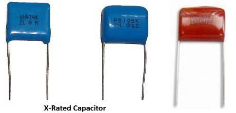
The easy and straight forward approach is to use step-down transformer to low down the AC, but the disadvantages of using transformer are that they expensive in cost, heavy in weight and big in size. We have already covered this type of AC to DC conversion, using Transformer in this article Cell Phone Charger Circuit. And yes, we can also convert the High voltage AC into Low voltage DC, without using the Transformer, this is called Transformerless power supply. The main component of a Transformerless power supply circuit is Voltage dropping capacitor or X-rated capacitor, which are specially designed for AC mains. This X rated capacitor is connected in series of Phase line of AC, to drop the voltage. This type of Transformer less power supply is called Capacitor Power Supply.
X-Rated Capacitor
As mentioned they are connected in series with phase line of AC to lower down the voltage, they are available in 230v, 400v, 600v AC or higher ratings.
Below is the table for output current and output voltage (without the Load), of different values of X-rated capacitors:
Capacitor Code | Capacitor value | Voltage | Current |
104k | 0.1 uF | 4 v | 8 mA |
334k | 0.33 uF | 10 v | 22 mA |
474k | 0.47 uF | 12 v | 25 mA |
684k | 0.68 uF | 18 v | 100 mA |
105k | 1 uF | 24 v | 40 mA |
225k | 2.2 uF | 24 v | 100 mA |
Selection of voltage dropping capacitor is important, it is based on Reactance of Capacitor and the amount of current to be withdrawn. The Reactance of the capacitor is given by below formula:
X = 1 / 2¶fC
X = Reactance of Capacitor
f = frequency of AC
C = Capacitance of X rated capacitor
We have used 474k means 0.47uF capacitor and frequency of AV mains is 50 Hz so the Reactance X is:
X = 1 / 2*3.14*50*0.47*10-6 = 6776 ohm (approx)
Now we can calculate the current (I) in the circuit:
I = V/X = 230/6775 = 34mA
So that’s how the Reactance and Current is calculated.
Circuit Explanation
Circuit is simple, Voltage dropping capacitor of 0.47uF is connected in series with Phase line of AC, this is a non-polarised capacitors so it can be connected from any side. A 470k ohm resistor is connected in parallel of Capacitor, to discharge the stored current in the capacitor when circuit is switched off, thus preventing from electric shock. This resistance is called Bleeder resistance.

Further Bridge rectifier (combination of 4 diodes) has been used to remove the negative half component of AC. This process is called the Rectification. And 1000uF/50v capacitor has been used for Filtration, means removing the ripples in resulted wave. And finally a Zener diode of 6.2v/1w is used as voltage regulator. As we know this circuit provides approx. 12v output (see the table above), so this Zener diode regulate it to approx. 6.2v voltage and flow back the extra current. A different value of Zener diode can also be used for desired voltage like 5.1v, 8v etc. An LED is connected for indication and testing purpose. R3 (100 ohm) is used as a current limiting resistor.
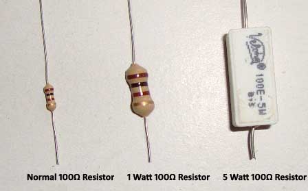
Use 1 Watt or above (5w) rating resistor, especially resistor R4. Otherwise it will burn after some time. They are usually thicker than usual resistor. Below is the diagram for different type of resistors:
Advantages of this transformerless power supply over transformer based supply are that: It is cost effective, lighter and smaller.
Notes
- Make it on your own risk, its extremely dangerous to work with AC mains without proper experience and precaution. Do take extreme caution while building this circuit.
- Don’t replace X-Rated capacitor with normal capacitor, otherwise it will burst.
- If more output voltage and output current is required then use different value of X-Rated capacitor, according to the table.
- Only use 1 Watt or above (5w) rating resistor and Zener diode.
- A 1 ampere fuse can also be used before X-rated capacitor, in series with phase line, for safety purpose.
- IC voltage regulator can also be used in place of Zener diode for voltage regulation.
Comments
Connections in Circuit diagram and in Image (with orange multimeter), both are same and correct. Please check carefully.
Thanks
sir HPB is correct there is mistake in circuit diagram
Yeah, the schematic doesn't match the demonstrated circuit. D1-4 make up a bridge rectifier. AC goes in between D1/D2 and also D3/D4. DC ground is between D1/D3 while +V is between D2/D4. The schematic shows C1/R1 incorrectly connected between D1/D3 when it should be connected between D1/D2.
Normally the resistors usually withstand 100 V, so you would have to place two series resistors of the same value (each of half the original value). Unless otherwise specified.
Should correct the circuit.
Your explanation is very helpful sir . THANK YOU
Could you run this converter, or any AC/DC adapter, backwards to attach a battery to the output leads and get AC out of the plug?
Bob Clark
Check this one: 12v DC to 220v AC Inverter Circuit
nope sir, thats so imposible
Sir i am so happy to read this information
And i request you sir please give some information about cfl circuit.
Thanks
What's the purpose of using R4?
Is that possible to use a 7K ohm 7watts resistor instead of C1?
Jayant, thanks for the information.
What's the purpose of R2?
Dear sir,
I want to give connection to 60led light's 4mm,so much capacitor, filter, resistance. .pls tell me sir. .
But I have tried with 474k 400 v ,filter 250v 10uf..470 k resistance. ...but light getting hot. ..
Dear SIr;
I want transformer less 12 V 2 Amp Current ,
but when i use the high value capacitor the current is become very less than the required value.
kindly provide me your suggestion how to improve the Current in the ckt.
Try to include 2 or 3 more same value capacitor in parallel with C1, and always proceed with caution as it involves AC mains.
Nice work. I've tried it and it worked. But my problem is that the circuit has a flow back current from the battery when not charging
This is not battery charger circuit, check this one:12v Battery Charger Circuit using LM317
Thank you sir, i try the circuit and is working well, please i need your full name so that i can refer you i my work.
I want to ask about the x-rated capacitors voltage output...
how can we calculate its output voltage? like in given table you have put the voltage values (4v, 12v ,24v) of different capacitors.
and when finding currents we divide the reactance with 230V, does capacitor drop all input voltages of circuit? then how output voltages produces....???
Capacitor doesn't drop all the voltage, it drops to a value given in the table.
1K resistor connected to LED described as 100 ohm in text. Must be 100 ohm in circuit.
Thanks a lot for the simplest, cheapest and easiest circuit. However I am little confused about the Voltage Output you have tabled against each x-rated capacitor?
We can calculate the Current as you did, but what about the Output Voltage? Please explain as it is a very important part in further expansion of the circuit.
Regards
This design is not considered safe. So do not use for DIY. If you design electronic for a living (like me) then there will be places it can be safely used. But they are limited.
This is not considered safe. Due to potential for low voltage rail becoming hazardous. Do not use for DIY.
What load can i connect on to the circuit?
The max load is determined by the capacitive reactance. Xc = 1/2pi*f*c where f = frequency and c is in microfarads. Also remember that mains voltages are RMS voltages. To get the proper capacitor voltage rating, multiply the mains voltage by 1.414 (to get peak-to-peak voltage).
How do recognized normal and x rated capacitors in normal look can i use DEC/MED/J0 1.K400 polyester capacitor?
One can use any polyester capacitor provided one calculates the proper voltage rating required. This is done as follows: Take the available mains voltage and multiply it by 1.414 to get the peak-to-peak voltage. I usually add a safety margin as well to compensate for surges. Thus, if the local mains voltage is 110Vac, then one can use a capacitor rated at 250V (minimum rating !). If the local voltage is 240Vac, then one can use a capacitor rated at 400V (minimum rating !). Since I live in an area that has a 240V AC supply, I prefer to use a cap with a 630V rating (added safety margin).
I designed the circuit but I measured 180v across the output terminals!! Am wondering why!!
Voltage is load dependent !! The closer one comes to the maximum available current, the lower the voltage. This why this type of circuit must always be designed with the load in mind. Open circuit gives maximum voltage across the terminals !!
Few of people are getting confused because of the rectifier part as they are much familiar with the rectifier configuration shown in image in twisted form but the combination in circuit diagram is also perfect so no need to to think about it. It's perfect and working flawlessly.
Thank you Circuit digest.
how to increase amps this circuit and loading time auto matic a reduced voltage how to resolve the problem
How can I increase the current.
Thank you
Since the value of the X-rated capacitor in this project is 474k the current is limited to 25mA. You can choose other value of capacitor as explained in the table aobe to increase current
I think there is error in the conversion of 105k and 225k. It should be 0.1uf and 0.22 uf respectively and not 1 uf and 2.2 uf as stasted in the table.
sir which calculation through we putting the resistor in parallel through capacitor and after bridge how we putting the capacitor of value and resistor for filteration.
for example if i need 5 volt and 3 ampere so what calculation is i perform through resistor and capacitor as after bridge for filteration.
can we use 2 zener diodes and 2 normal diodes in place of 4 normal diodes???
No,
The function of a Zener diode is totally different that that of a Normal diode. Use only normal diodes for this project
Any one can explain how the calculation are done. And how can i change the output current and voltages. if there is a formula can you please share me... And how can i simulate the above circuit in MATLAB, also i dont know how to simulate X - Rated capacitors in MATLAB Software. Thankink You..
sir kindly provide the 5 volt 2 ampere transformerless power supply
You have to use the SMPS method to get 5Volt 2A. This method will not work
Hi sir, Your explaination is too good.I have cleared my doubt by refering your explaination . Thank you!
Hai sir,
I'm using 100ohm 1Watt resistor as R4, but it starts to hot and burning..why it is happening...if i did'nt use R4, c2 getting hotter..please help me.
Hi,
How long can this circuit run at a time? I mean how long does it take to overheat and burn?
Can I run this for a whole week without unplugging?
Assuming proper voltage rating for the capacitor, and a current limited load, one can run it forever. For example: I use a simpler version (no zener, etc) to run a 3W LED downlight, and it has been running now for 3 years continuously. Just do not short-circuit the circuit. There must be a load.
Although within the circuit there is only few volts output, BETWEEN the whole circuit, and the REST of the world, and that means your floor, your walls and yourself, there can be full mains voltage! 230 V RMS (320 V peak) I understand that purpose of resistor on the other mains line is to create another safety barrier in case phase would end up on this side of the circuit but remember components fail sometimes. That's why power supplies meant for end users are always galvanically separated from mains voltage.
True that, the circuit is only for understanding the concept and does not serve any practical value
No practical value ? All LED down-lights and several LED emergency lights use this very principle.
Hi CD
A question: Is it necessary for R4 to be 100 ohms or coult it be higher, like 1K ohm?
Aprecciate your help and your time. Thanks.
If one increases the value of R4, one simply decreases the amount of available current. Effectively, one is adding resistance to the capacitive reactance. (Xc + R)
I have a mini inverter for 3 cfl lamps.the stepdown transformer has been burnt.shall i use this circuit instead of tranformer to my inverter? Plz help me.
can i use 400 volt 684 j ?????
what happens if I use 1000uf-16v capacitor instead of 50v? I want to use smd parts and 16v is more convenient for me. would it cause a problem?
No should not use a 16V capacitor in place of 50V. The capacitor will burst. Also this circuit cannot be made using smd components
how vollt and am.. out its kit
what capacitor value should i select if My load current is 0.7A . Voltage input range is 80-160v AC. ?
I want to know what are the drawbacks of this circuit?
1st great creative idea sir, I enjoy your article on Transformerless Power Supply. I want to know, what is purpose of R4 Resistor on second line of main and what Happened, absence of R4 in this circuit .
Kindly Waiting Your Reply. have a great day
What is the efficiency if this circuit???
is it safety to connect its output(5v) to arduino
It is safe but add an overvoltage protection circuit using a zener R, just to stay on safe side
Please how can we calculate out the DC voltage of a ceramic capacitors thanks
I gave 245 v AC input to poly. capacitor ( 0.22uF 400V) and surprised to note the output of 220V AC.
In comparison with your table the output is very excess. As per your calculation It should below 24V.
What can be the reason.?
Hello,
As per the circuit diagram we test the circuit and we measure the cureent between R2 and R3. But we get the micro ampere reading on our DMM. I don't know exactly what happe in this circuit. Could any oe help me to find the solution?

Under "Circuit Explanation" circuit diagram, the 400Vac X rated capacitor output
should be connected to mid-point between D1 and D2.
I believe this was in error, as components with twisted connections by
orange multimeter shows correct and intended circuit.