

Most of our electronics projects are powered by a Lead Acid battery, in this project let us discuss how to recharge this lead acid Battery with a help of a simple circuit that can be easily understood and built from home. This project will save yourself from investing in a battery charger and help you to extend your battery life. So let's get started!!!!
Let's start by understanding few basic things about a Lead Acid Battery so that we can build our charger more efficiently. Most of the lead acid batteries in the market are 12V batteries. The Ah (Ampere hours) of each battery may vary based on the required capacity, a 7 Ah battery for example will be able to provide 1 Amps for a duration of 7 hours (1 Amps *7 hours = 7 Ah). Now after complete discharge the battery percentage should be around 10.5, this is the time for us to charge our batteries. The charging current of a battery is recommended to be 1/10th of the Ah rating of the battery. So for a 7 Ah battery the charging current should be around 0.7 Amps. Current greater than this may harm the battery resulting in reduced battery life. Keeping this in consideration this, small homemade charger will be able to provide you variable voltage and variable current. The current can be adjusted based on the present Ah rating of the battery.
This Lead Acid Battery charger circuit can also be used to charge your mobile phones, after adjusting the voltage and current according to mobile phone, using the POT. This circuit will provide a Regulated DC Power Supply from the AC mains and will work as AC-DC Adapter; I have previously created a Variable Power Supply with High current and voltage output.
Components Required:
- Transformer 12V 1Amp
- IC LM317 (2)
- Diode Bridge W005
- Connector Terminal Block (2)
- Capacitor 1000uF, 1uF
- Capacitor 0.1uF (5)
- Variable resistor 100R
- Resistor 1k (5)
- Resistor 10k
- Diode- Nn007 (3)
- LM358 – Opamp
- 0.05R - Shunt Resistor/wire
- LCD-16*2 (optional)
- Arduino Nano (optional)
Circuit Explanation:
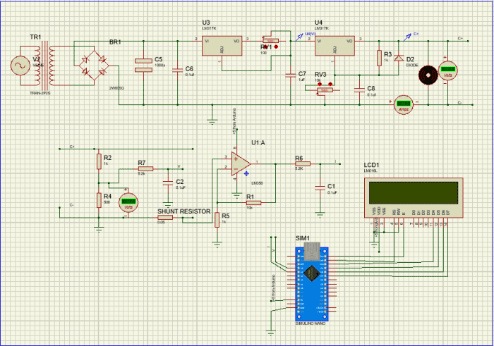
The complete schematics of this Battery Charger Circuit are shown below:

The main objective of our 12V power supply circuit is to control the voltage and current for the battery so that it can be charged in the best possible way. For this purpose we have used two LM317 ICs, one is used to control the voltage and the other is used to limit the current. Here, in our circuit the IC U1 is used to control the current and the IC U3 is used to control the voltage. I would strongly recommend you to read the datasheet of LM317 and understand it, so that it comes in handy while trying similar projects since LM317 is a most used Variable regulator.
Voltage Regulator Circuit:
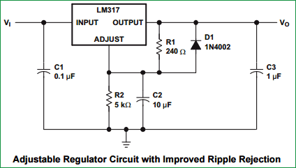
A simple Voltage Regulator Circuit, taken from LM317’s datasheet, is shown in the figure above. Here the output voltage is decided by the resistor values R1 and R2, in our case the resistor R2 is used as a variable resistor to control the output voltage. The formulae to calculate the output voltage is Vout = 1.25 (1+R2/R1). Using this formulae, the value of resistance 1K (R8) and 10K – pot (RV2) is selected. You can also use this LM317 calculator to calculate the value of R2.
Current Limiter Circuit:
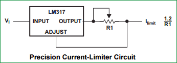
The Current Limiter Circuit, taken from LM317’s datasheet, is shown in the above figure; this is a simple circuit which can be used to limit the current in our circuit based on the resistance value R1. The formulae to calculate the output current is Iout= 1.2/R1. Based on these formulae the value of pot RV1 is selected as 100R.
Hence, in order to control the current and voltage two potentiometers RV1 and RV2 are used respectively as shown in the schematics above. The LM317 is powered by a diode bridge; the Diode Bridge itself is connected to a Transformer through connector P1. The rating of the transformer is 12V 1 Amps. This circuit alone is sufficient for us to make a simple circuit, but with help of few additional set up we can monitor the current and voltage of our charger on LCD, which is explained below.
Display Voltage and Current on LCD using Arduino:
With the help of an Arduino Nano and an LCD (16*2), we can display the voltage and current values of our charger. But, how can we do this!!
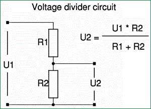
Arduino Nano is 5V operational Microcontroller, anything more than 5V will kill it. But, our charger works on 12V, hence with the help of a Voltage divider circuit the value of (0-14) Volt is mapped down to (0-5)V using resistor R1 (1k) and R2 (500R), like have previously done in 0-24v 3A Regulated Power Supply Circuit, to display the Voltage on LCD using Arduino Nano.
To measure the current we use a shunt resistor R4 of very low value to create a voltage drop across the resistor, as you can see in the circuit below. Now using Ohms Law calculator we can calculate the current passing through the resistor using the formulae I=V/R.


In our circuit the value of R4 is 0.05R and the maximum current that can pass through our circuit will be 1.2 Amps because the transformer is rated so. The power rating of the resistor can be calculated using P=I^2 R. In our case P=(1.2*1.2*0.05) => 0.07 which is less than a quarter watt. But if you do not get a 0.05R or if your current rating is higher, then calculate the Power accordingly. Now if we are able to measure the voltage drop across the resistor R4, we would be able to calculate the current through the circuit using our Arduino. But, this voltage drop is very minimal for our Arduino to read it. Hence an Amplifier circuit is constructed using Op-amp LM358 as shown in the figure above, the output of this Op-Amp is given to our Arduino through an R-C circuit to measure the current and display in on the LCD.
Once we decide our value of components in our circuit, it is always recommended to use simulation software to verify our values before we proceed with our actual hardware. Here, I have used Proteus 8 to simulate the circuit as shown below. You can run the simulation using the file (12V_charger.pdsprj) given in this zip file.
Building up the Battery Charger:
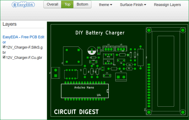
Once you are ready with the circuit you can start building up your charger, you can either use a Perf board for this project or build your own PCB. I have used a PCB, the PCB was created using KICAD.is open source PCB designing software and can be downloaded online for free. If you are not familiar with PCB designing, no worries!!!. I have attached the Gerber and other print files (download here), which can be handed over to your local PCB manufacturer and your board can be fabricated. You can also see how your PCB will look after manufacturing, by uploading these Gerber files (zip file) to any Gerber Viewer. The PCB design of our charger is shown below.
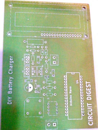
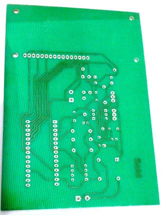
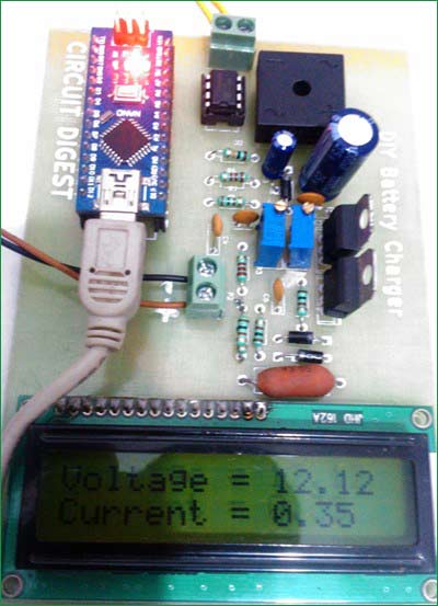
Once the PCB is fabricated, assemble and solder the components based on values given in the schematics, for your convenience a BOM (Bill of materials) is also attached in the zip file given above, so that you can purchase and assemble them at ease. After assembling our Charger should look something like this....
Testing of Battery Charger:
Now it is time to test our charger, the Arduino and LCD is not required for the charger to operate. They are used only for monitoring purpose. You can mount them using Bergstick as shown above, so that you can remove them when you need them for another project.
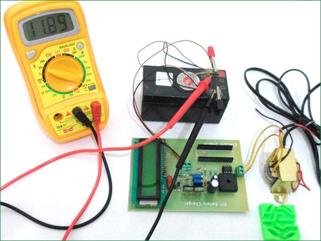
For testing purpose remove the Arduino and connect your transformer, now adjust the output voltage to our required voltage using the POT RV2. Verify the voltage using a multimeter and connect it to the battery as shown below. That is it our charger is now operational.
Now before we plug in our Arduino test the incoming voltage to our Arduino Nano pin A0 and A1, it should not exceed 5V if out circuit is working properly. If everything is fine connect your Arduino and LCD. Use the given below Program to upload in your Arduino. This program will just display the Voltage and Current value of our charger, we can use this to set our voltage and monitor if our battery is being charged correctly. Check the Video given Below.
If everything works as expected, you should get a display on LCD as shown in the previous figures. Now, everything is done, all we have to do is connect our charger to any 12V battery and charge it using a preferred voltage and current. Same charger can also be used to charge your mobile phone, but check the current and voltage rating needed to charge the mobile phone, before connecting. You also need to attach USB cable to our circuit to charge cell phone.
If you have any doubt please feel free to use the comment section. We are always ready to help you!!
HAPPY LEARNING!!!!
Complete Project Code
#include <LiquidCrystal.h>
// initialize the library with the numbers of the interface pins
LiquidCrystal lcd(11, 12, 10, 9, 8, 7);
float voltage,current;
void setup()
{
  Serial.begin(9600);
  // set up the LCD's number of columns and rows:
  lcd.begin(16, 2);
  // Print a message to the LCD.
  lcd.setCursor(0, 0);
  lcd.print("12V Charger");
  lcd.setCursor(0, 1);
  lcd.print("-Circuit Digest");
  delay(2000);
  lcd.clear();
  lcd.setCursor(0, 0);
  lcd.print("Voltage = ");
  lcd.setCursor(0, 1);
  lcd.print("Current = ");
}
void loop()
{
  voltage = (analogRead(A0)) * 0.0140625;
  current = (analogRead(A1)) * 0.35;

  lcd.setCursor(10,0);
  lcd.print(voltage);
  lcd.setCursor(10,1);
  lcd.print(current);

  delay(1000);
}
Comments
Hi will this project works safely for charging 12v,7.5ah battery?
But I've tried this first on bread board the current is getting controlled but I'm not able to vary the voltage.what will be the problem?
"Voltage Regulator Circuit:
A simple Voltage Regulator Circuit, taken from LM317’s datasheet, is shown in the figure above. Here the output voltage is decided by the resistor values R1 and R2, in our case the resistor R2 is used as a variable resistor to control the output voltage. The formulae to calculate the output voltage is Vout = 1.25 (1+R2/R1). Using this formulae, the value of resistance 1K (R8) and 10K – pot (RV2) is selected."
Changing thr value of R2 should change the output voltage, if it does not get changed kindly check your connections. Remove the current controlling circuit and try the voltage regulation circuit alone.
Does this charge automatically? As in, does it automatically charge when it gets below a certain threshold and does it automatically stop charging when it gets above a certain threshold?
The output voltage of the circuit is adjustable, so say we fixed the voltage at 14V. Now when a battery of 11V is connected the battery gets charged due to the potential difference. Now gradually the voltage of the battery increases, when it reaches near 14V there will no longer be any potential difference and the charging will stop.
This circuit does not have any features like auto cut-off, it can just simply be used to charge your 12V lead acid batteries and monitor your charging rate.
I have one question if I replace the rectifier part of the circuit (transformer, bridge rectifier, and 2 capacitors C2 and C3) with a combination of two solar panels (12V 10W each) in which each panel produces 20V max, what changes I would have to make in the circuit? How should I connect the panel's -series or panels.
can this be used to charge lithium ion batteries? I have a battery which requires the following charging characteristic :
Li-ion 18650 26f samsung 3.7V 2600mAh
constant current charge, followed by constant voltage charge when the battery reaches 4.2V.
How can I design such a circuit using LM317?
.hey all..what are the modification needed to be done in this circuit if we want to use 24v battery
nice project
it is okey if i replace source with turbine?
Yes you can replace, but make sure it can source enough voltage and current.
Hi again. actually my project is to charge the lithium ion battery 18650 and discharging using usb female to charge the phone. it is possible that i used this circuit? Actually the source produce 5v to 8 volt voltage , so do i need to add something there.
when the discharging to the load, the value in the display will reduced?sorry there are so many question, i appriciated that you able to help me :-)
No this project is no way related to your application. Instead check this out
https://circuitdigest.com/electronic-circuits/power-bank-circuit
You would be able to figure it out yourself
Bear in mind that there should be a capacitot ( 2.2 uF to ground ) on the output of each 12 bVolt regulator , as they do have a tendency to oscillate .
nice bit of circuitry though .
THE CIRCUIT IS WORKING FINE BUT THE IC USED FOR VOLTAGE REGULATION IS SEVERELY HEATING.....EVEN WHEN THE CURRENT FLOWING THROUGH THE IC IS JUST 200mA SO PLEASE ANY ONE GIVE ME SUGGESTION TO SOLVE THIS PROBLEM RATHER THAN PUTTING HEAT SINK
IF there is too much heating for 200mA it means there is some problem with the circuit. Check the circuit and find if there is any problem on how the Regulator are connected. Are both of them getting hot?
I'VE CROSS CHECKED THE CONNECTIONS FOR 3-4 TIMES. EVERYTHING IS WORKING FINE THE VOLTAGE IS VARYING FROM 1.5-24 AND EVEN THE CURRENT IS ALSO GETTING VARIED.BUT MY PROBLEM IS HEATING OF IC.DUE TO THE HEATING NOW AT PRESENT IM USING CPU COOLING FAN.IN YOUR CIRCUIT YOU'VE NOT EVEN USED THE HEAT SINK.....AS YOU'VE ASKED,ONLY THE IC USED FOR VOLTAGE REGULATION IS HEATING.THE IS FOR CURRENT REGULATION IS ALSO HEATING..,BUT IT IS WELL WITHIN THE TOLERABLE LIMIT..THAT'S COMMON...
sir i have connected the ends where c+ and c- are written and also connected all the ends but when i run the proteus circuit the voltage becomes zero and led shows current 2.05 please can you send me proteus stimulating circuit with all 3 circuits proper connected and connections please send it to me i havee to submit this project as my semester project sir please
What is the use of that feedback diode?
why are the two schematic diagram different? >> I mean that one for simulation have connection of adj and C8
on simulating the circuit, voltmeter shows no reading.
and why motor is used ?
Hy Sir
May I please have the code to simulate this project. I tried it using codeblocks and it gave me errors
How much cost is needed
Why there is a difference between simulation circuit and the other one in the beginning? Why not the capacitor is connected to adj pin of ic2 in the first circuit?
my requirement to pcb 12volt input with charging and output a.c,d.c.power
Nice project sir but i want to know how you get this number
void loop()
{
voltage = (analogRead(A0)) * 0.0140625;
current = (analogRead(A1)) * 0.35;
can you explain this thank you
This is the value of multiplier that we have to use to get the actual value of current and voltage.
The analog Read function of Arduino will give us values from 0-1024. This value will be change proportinal to voltage and current.
To get the actual value of voltage and current we have to multiply this analog value with a multiplier value. The value of multiplier can be obtained by measuring a known value of voltage and current.
For example if we get 125 and 423 as the analog values when measuring 5V and 1.2A respectively. Then multiplier value can be calculated by 5/125 and 1.2/423 for calculating the actual value of voltage and current.
I am just confused while simulating this circuit in proteus can you please tell me how to do so
its not displaying anything
How to get the readymade pcb available??
I need it soon

100/100