

We all face power cuts in our houses or offices some time or another. At those times we generally use Generator or an Inverter. Power generators use petrol or diesel as fuel and they are noisy. We will not be discussing about the power generators here. Here we will be talking about the Inverter. Inverters drive the power from DC power banks, like lead acid battery pack. These inverters are used everywhere now. This type can be used for medium power applications. But for high power appliances Power generators are most preferred one.
The most common type of inverter we see in everyday life is UPS (Uninterruptible Power Supply). We use UPS to keep PC (Personal Computer) running in the event of power cuts. UPS keeps up the power delivered until battery bank runs out.
UPS is a system which converts DC to AC. So, UPS takes DC power of battery as input and gives AC power as output. Today we are going to build a 100 watt 12v DC to 220v AC inverter. This Circuit is simple and very useful.
Required Components:
- +12 v battery
- 47KΩ resistor
- 1000µF capacitor (2 pieces)
- 4700µF capacitor
- 10k pot, 1k resistor (2pieces)
- 10k resistor (2pieces)
- In5408 diodes (2pieces)
- CD4047 IC
- 4.7µF capacitor
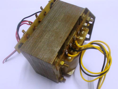
- Step down transformer (220v to 12v-0-12v (center tap)) (10Amp)
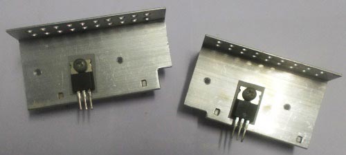
- IRF540N MOSFET (2pieces)
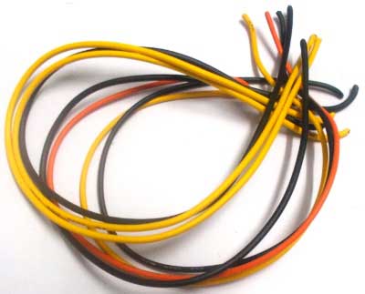
- Wires
12v-0-12v 10Amp Step down transformer:
IRF540N MOSFET should be used with heat sink, do not use the MOSFET without proper heat sink, without them the MOSFET cannot stand. The MOSFET here is n channel enhancement MOSFET.
Also use some good gauge wire. If you use small gauge wire, you will have losses and under heavy loads they become immensely hot and they will burn out.
Circuit Explanation:
Circuit diagram of 100 watt DC to AC inverter has been given below. We have used EasyEDA to draw this Circuit Diagram, and covered a tutorial on ‘How to use EasyEDA for Drawing and Simulating the circuits’. You can also covert this Circuit Diagram into PCB layout, as we have explained in EasyEDA tutorial, and build this project on PCB.

Working Explanation:
The core of the circuit is CD4047 chip; this chip here acts as an Astable Multivibrator. So the chip generates clock pulses of frequency 50Hz. This frequency is chosen by capacitor C2 and resistor R1. The time period for the signal is given as:
T = 4.71 R1*C2.
Now to get frequency (1/T) of 50Hz, we need to play with the above numbers. We can choose capacitance as a constant and play with resistance for appropriate frequency. But if you don’t have an oscilloscope to adjust the pot for the exact resistance, choose capacitance as 4.7µF and resistance as 1KΩ. This gives a frequency of 47Hz, which would do just fine for simple loads. If you want to get exact frequency you need to select the resistance accurately.
So the chip generates the clock pulses, these pulses are taken to N-MOSFET to drive the transformer. The transformer steps up the 12V to 230V. So every time a pulse reaches the MOSFET gate, we will have a 220V half cycle at the output. In the next pulse, the second MOSFET triggers for the second half cycle of 220V. So with two MOSFETS turning on and off at 50Hz frequency, we will have 50Hz 220V cycle output at the transformer end.
So we have made a 12V DC to 220V AC Inverter Circuit.
Comments
what is capacitor voltage range ... c12000u 16v and others? and R1 pot third foot connect ground or empty
very useful circuits thank you dear.
I think at the first time output from IC, M2 MOSFET will work not M1,as M1 MOSFET does not work with gate negative.May you tell me about second pulse incoming from output from IC 4047.( Correct me if I am wrong.)
Please give me response.
It is a good and very useful please send circuit diagram and other details regarding inverter.
Please give resistor type and wattage. i guess all are .25w is it
any circuit i can built for my 6v battery i mean mini inverter or booster pls
a simple but effective
help me ty
a schematic diagram will work too
thank you
It is a very good clt butwàve is squar wave so this is lightly wrong otherwise it is a good item
Am grateful for this project because we tried it out and it has worked out for us.
thanks
I have looked at data sheet for IC 4047 and i think pin 6 is wrongly placed . it should be connected to 4,5 & 14 to run as a free running Astable multivibrator
In 1,2 input which is + and-
Can we use I amp transformer
what is the capacitors voltage
I have built similar devices to this one, at higher frequency's. It's an effective circuit, but please be careful chaps, this is still 240volt and can bite you hard if you are careless...
I want to use this circuit to build a 400 W UPS for my PC. How do I upgrade the 100 W circuit to 400 W please? Which components should be changed?
Thanks
Jagath
i made this circuit completely at the end output is coming without putting transformer which is 25 volts AC but when i put transformer its output is not coming and battery is getting hot instantley. what to do i am facing very much trouble please leave a note to overcome this problem. square wave is coming out of pins in 4047 . i checked it on oscilloscope . every thing is fine ac is coming but when putting transformer to step up it is making problem.
circuit is not working m2 is not working what can i do
m1 is not working output is not take
Is this inverter sin wave or square wave?
Please response
This 12v DC to 220v AC Inverter Circuit comes very useful during my search.
12 v DC conv. into AC and ac work upto 300Khz frqu. rang how it ckt mahe it
when i measure the output voltage before the transformer is 25.8V but when the transformer passes 15-0-15V 3A is not out 220VAC. Can you help me? Pls
have you connected any load on the output side? How much voltage are you measuring?
Anyone help me??? :(((

Useful circuit