

Digital and Analog is an integral part of Electronics. Most of the devices have both ADC as well as DAC and they are used when there is a need of converting signals either from analog to digital or digital to analog. Also the real world signals like sound and light are analog in the nature, so whenever these real world signals have to be used, the digital signals have to be converted to analog, for example to produce sound using Speakers or to control a light source.
Another type of DAC is a Pulse Width Modulator (PWM). A PWM takes a digital word and generates a digital pulse with variable pulse width. When this signal is passed through a filter, the result will be purely analog. An analog signal can have multiple types of data in a signal.
In this tutorial, we will interface DAC MCP4921 with Microchip PIC16F877A for digital to analog conversion.
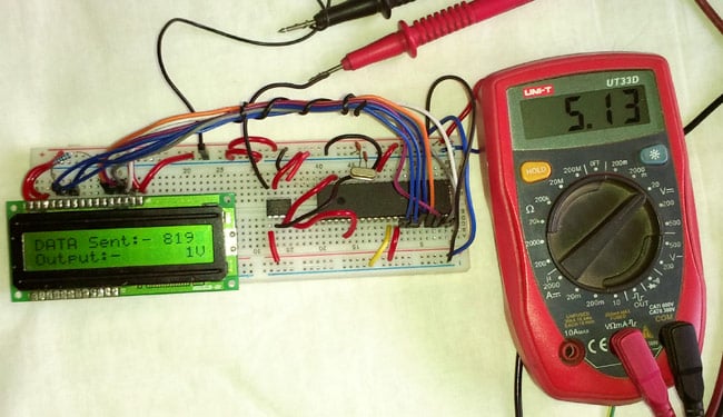
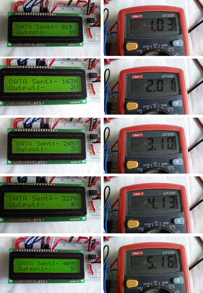
Here in this tutorial we will convert the digital signal into an analog signal and display the input digital value and output analog value on 16x2 LCD. It will provide 1V, 2V, 3V, 4V, and 5V as the final analog output which is demonstrated in the video given at the end. You can further learn about DAC in our precious tutorial of DAC interfacing with Raspberry Pi, Arduino and STM32 boards.
DAC can be used in many applications such as Motor control, Control Brightness of the LED Lights, Audio Amplifier, Video Encoders, Data Acquisition Systems etc. Before jumping directly to the interfacing part, it is important to have an overview about MCP4921.
MCP4921 DAC (Digital to Analog Converter)
MCP4921 is a 12 bit DAC, so MCP4921 will provide 12 bits of output resolution. DAC resolution means number of digital bits that can be converted into analog signal. How many values we can achieve from this is based on the formula . For 12-bit, it is = 4096. This means 12-bit resolution DAC could produce 4096 different outputs.
By using this value, one can easily calculate the single analog step voltage. For calculating the steps, the reference voltage is required. As the logic voltage for the device is 5V, the step voltage is 5/4095 (4096-1 because the starting point for digital is not 1, it is 0), which is 0.00122100122 millivolt. So, a change of 1 bit will change the analog output with 0.00122100122.
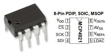
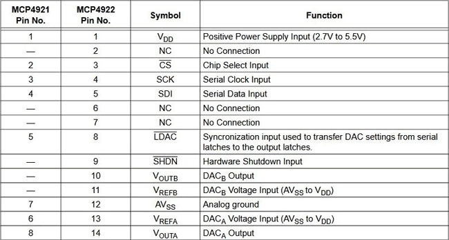
So, that was the conversion part. The MCP4921 is an 8-pin IC. The pin diagram and the description can be found below.
The MCP4921 IC communicates with the microcontroller by the SPI protocol. For SPI communication, a device has to be master, which submits data or command to the external device connected as a slave. In SPI communication system, multiple slave devices can be connected with the single Master Device.
To submit the data and the command, it is important to understand the command register.
In the below image, the command register is shown,
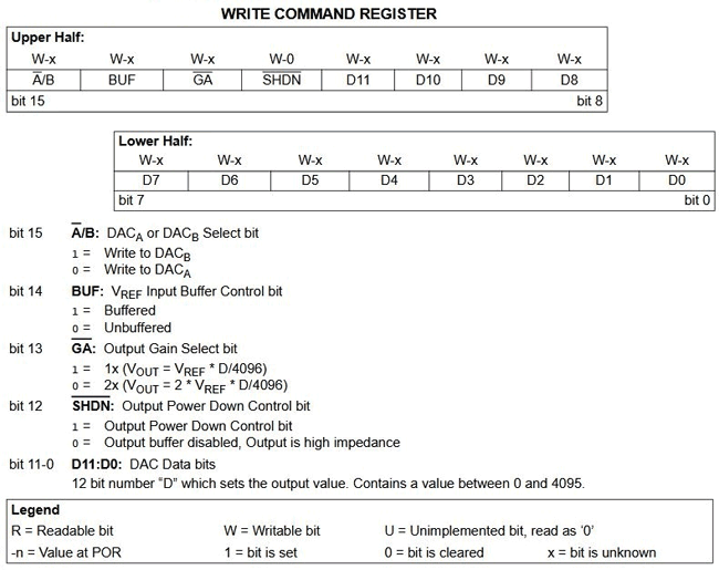
The command register is a 16-bit register. The bit-15 to bit-12 is used for the configuration command. The data input and the configuration is clearly shown in the above image. In this project, the MCP4921 will be used as the following configuration-
|
Bit Number |
Configuration |
Configuration Value |
|
Bit 15 |
DACA |
0 |
|
Bit 14 |
Unbuffered |
0 |
|
Bit 13 |
1x(VOUT*D/4096) |
1 |
|
Bit 12 |
Output Power Down Control Bit |
1 |
So the Binary is 0011 along with the data which is determined by the D11 to D0 bits of the register. The 16-bit data 0011 xxxx xxxx xxxx need to be submitted where the first 4 bit of MSB is the configuration and the rest is the LSB. It will be clearer by seeing the write command timing diagram.
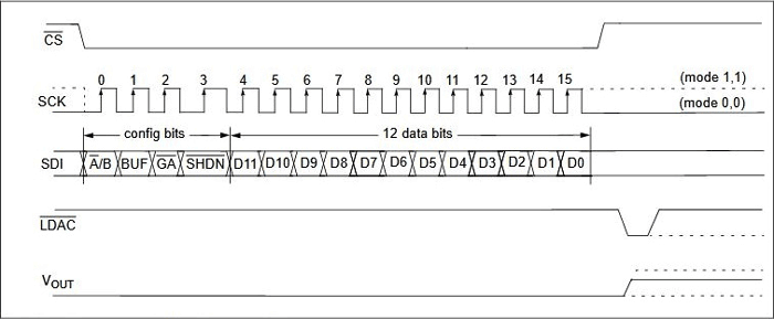
As per the timing diagram and the datasheet, the CS pin is low for the entire command writing period to the MCP4921.
Now it is the time to interface the device with the hardware and writing the codes.
Components Required
For this project, the following components are required-
- MCP4921
- PIC16F877A
- 20 MHz Crystal
- A Display 16x2 character LCD.
- 2k resistor -1 pc
- 33pF capacitors - 2 pcs
- 4.7k resistor - 1 pc
- A multi-meter to measure the output voltage
- A breadboard
- 5V power supply, A phone charger can work.
- Lots of hookup wires or berg wires.
- Microchip programming environment with Programmer kit and IDE with compiler
Schematic
Circuit Diagram for interfacing DAC4921 with PIC Microcontroller is given below:

The circuit is constructed in Breadboard-
Code Explanation
Complete code for converting Digital signals into analog with PIC16F877A is given at the end of article. As always, we first need to set the configuration bits in the PIC microcontroller.
// PIC16F877A Configuration Bit Settings
// 'C' source line config statements
// CONFIG

#pragma config FOSC = HS        // Oscillator Selection bits (HS oscillator)
#pragma config WDTE = OFF       // Watchdog Timer Enable bit (WDT disabled)
#pragma config PWRTE = OFF      // Power-up Timer Enable bit (PWRT disabled)
#pragma config BOREN = ON       // Brown-out Reset Enable bit (BOR enabled)
#pragma config LVP = OFF         // Low-Voltage (Single-Supply) In-Circuit Serial Programming Enable bit (RB3/PGM pin has PGM function; low-voltage programming enabled)
#pragma config CPD = OFF        // Data EEPROM Memory Code Protection bit (Data EEPROM code protection off)
#pragma config WRT = OFF        // Flash Program Memory Write Enable bits (Write protection off; all program memory may be written to by EECON control)
#pragma config CP = OFF         // Flash Program Memory Code Protection bit (Code protection off)
The below code lines are used for integrating LCD and SPI header files, also the XTAL Frequency and the DAC’s CS pin connection is declared.
The PIC SPI tutorial and library can be found at the given link.
#include <xc.h>
#include <stdint.h>
#include "supporing_cfile\lcd.h"
#include "supporing_cfile\PIC16F877a_SPI.h"

/*
 Hardware related definition
 */

#define _XTAL_FREQ 200000000 //Crystal Frequency, used in delay
#define DAC_CS PORTCbits.RC0 //Declaring DAC CS pin
Funciton the SPI_Initialize_Master() is slightly modified for a different configuration required for this project. In this case, the SSPSTAT register is configured such a way that the input data sampled at end of data output time and the also the SPI clock configured as Transmit occurs on the transition from active to idle clock state mode. Other is the same.
void SPI_Initialize_Master()
{
                TRISC5 = 0; // Set as output
                SSPSTAT = 0b11000000; //pg 74/234
                SSPCON = 0b00100000; //pg 75/234
                TRISC3 = 0; //Set as output for slave mode
}
Also, for the below function, the SPI_Write() is modified slightly. Data transmission will occur after the buffer is cleared for ensuring perfect data transmission over SPI.
void SPI_Write(char incoming)
{
                SSPBUF = incoming; //Write the user given data into buffer
                while (!SSPSTATbits.BF);
}
The important part of the program is the MCP4921 driver. It is slightly tricky part as the command and digital data is punched together to provide complete 16-bit data over the SPI. However, that logic is clearly shown in the code comments.
/*
 This Function is for converting the digital value to the analog.
 */
void convert_DAC(unsigned int value)
{
   /*Step Size = 2^n, Therefore 12bit 2^12 = 4096
     For 5V reference, the step will be 5/4095 = 0.0012210012210012V or 1mV (approx)*/
  unsigned int container ;
  unsigned int MSB;
  unsigned int LSB;
  /*Step: 1, stored the 12 bit data into the container
   Suppose the data is 4095, in binary 1111 1111 1111*/
  container = value;
  /*Step: 2 Creating Dummy 8 bit. So, by dividing 256, upper 4 bits are captured in LSB
   LSB = 0000 1111*/
  LSB = container/256;
  /*Step: 3 Sending the configuration with punching the 4 bit data.
   LSB = 0011 0000 OR 0000 1111. Result is 0011 1111 */
  LSB = (0x30) | LSB;
  /*Step:4 Container still has the 21bit value. Extracting the lower 8 bits.
   1111 1111 AND 1111 1111 1111. Result is 1111 1111 which is MSB*/
  MSB = 0xFF & container;
 /*Step:4 Sending the 16bits data by dividing into two bytes. */
    DAC_CS = 0;     // CS is low during data transmission. As per the data-sheet it is required
    SPI_Write(LSB);
    SPI_Write(MSB);
    DAC_CS = 1;
}
In the main function, a ‘for loop’ is used where the digital data for creating the output of 1V, 2V, 3V, 4V, and 5V is created. The digital value is calculated against the Output voltage / 0.0012210012210012 millivolt.
void main() {
    system_init();
    introduction_screen();
    int number=0;
    int volt=0;
    while (1) {
        for (volt=1; volt<=MAX_VOLT; volt++){
            number = volt / 0.0012210012210012;
            clear_screen();
            lcd_com(FIRST_LINE);
            lcd_puts("DATA Sent:- ");
            lcd_print_number(number);
            lcd_com(SECOND_LINE);
            lcd_puts("Output:-      ");
            lcd_print_number(volt);
            lcd_puts("V");
            convert_DAC(number);
            __delay_ms(300);
        }
    }
}
Testing the Digital to Analog Conversion using PIC
The built circuit is tested using Multi-meter. In below images, the output voltage and the digital data is shown on the LCD. The Multi-meter is showing close reading.
Complete Code with a working video is attached below.
Complete Project Code
/*
 * File:   main.c
 * Author: Sourav Gupta *<|:-]
 * Created for: circuitdigest.com
 * Project On: mcp4921 interfacing
 * Created on March 21, 2019, 7:05 PM
 */
// PIC16F877A Configuration Bit Settings

// 'C' source line config statements

// CONFIG
#pragma config FOSC = HS        // Oscillator Selection bits (HS oscillator)
#pragma config WDTE = OFF       // Watchdog Timer Enable bit (WDT disabled)
#pragma config PWRTE = OFF      // Power-up Timer Enable bit (PWRT disabled)
#pragma config BOREN = ON       // Brown-out Reset Enable bit (BOR enabled)
#pragma config LVP = OFF         // Low-Voltage (Single-Supply) In-Circuit Serial Programming Enable bit (RB3/PGM pin has PGM function; low-voltage programming enabled)
#pragma config CPD = OFF        // Data EEPROM Memory Code Protection bit (Data EEPROM code protection off)
#pragma config WRT = OFF        // Flash Program Memory Write Enable bits (Write protection off; all program memory may be written to by EECON control)
#pragma config CP = OFF         // Flash Program Memory Code Protection bit (Code protection off)

#include <xc.h>
#include <stdint.h>
#include "supporing_cfile\lcd.h"
#include "supporing_cfile\PIC16F877a_SPI.h"

/*
 Hardware related definition
 */
#define _XTAL_FREQ 200000000 //Crystal Frequency, used in delay
#define DAC_CS PORTCbits.RC0 //Declaring DAC CS pin

/*
 Program Flow related definition
 */

#define MAX_VOLT 5
#define FIRST_LINE 0x80
#define SECOND_LINE 0xC0

/*
 Other Specific function definition
 */
void system_init(void);
void sw_delayms(unsigned int d);
void convert_DAC(unsigned int digital_value);
void clear_screen(void);
void introduction_screen(void);

void main() {
    system_init();
    introduction_screen();
    int number=0;
    int volt=0;
    while (1) {
        for (volt=1; volt<=MAX_VOLT; volt++){
            number = volt / 0.0012210012210012;
            clear_screen();
            lcd_com(FIRST_LINE);
            lcd_puts("DATA Sent:- ");
            lcd_print_number(number);
            lcd_com(SECOND_LINE);
            lcd_puts("Output:-      ");
            lcd_print_number(volt);
            lcd_puts("V");
            convert_DAC(number);
            __delay_ms(300);
        }
    }
}
/*
 This Function is for software delay.
 */

void sw_delayms(unsigned int d){
int x, y;
for(x=0;x<d;x++)
for(y=0;y<=1275;y++);
}
/*
 This Function is for system initializations.
 */

void system_init(void){
    TRISB = 0x00; // LCD pin as output
    TRISCbits.TRISC0=0; // CS pin declared as output
    lcd_init(); // This will initialize the lcd
    SPI_Initialize_Master();
}

/*
 This Function is for Clear screen without command.
 */

void clear_screen(void){
    lcd_com(FIRST_LINE);
    lcd_puts("                ");
    lcd_com(SECOND_LINE);
    lcd_puts("                ");
}

/*
 This Function is for playing introduction.
 */

void introduction_screen(void){
    lcd_com(FIRST_LINE);
    lcd_puts("Welcome to");
    lcd_com(SECOND_LINE);
    lcd_puts("circuit Digest");
    __delay_ms(500);
    clear_screen();
    lcd_com(FIRST_LINE);
    lcd_puts("mcp4921 with");
    lcd_com(SECOND_LINE);
    lcd_puts("PIC16F877A");
    __delay_ms(350);
}

/*
 This Function is for converting the digital value to the analog.
 */

void convert_DAC(unsigned int value)

{
    /*Step Size = 2^n, Therefore 12bit 2^12 = 4096
     For 5V reference, the step will be 5/4095 = 0.0012210012210012V or 1mV (approx)*/
  unsigned int container ;
  unsigned int MSB;
  unsigned int LSB;
  /*Step: 1, stored the 12 bit data into the container
   Suppose the data is 4095, in binary 1111 1111 1111*/
  container = value;
  /*Step: 2 Creating Dummy 8 bit. So, by dividing 256, upper 4 bits are captured in LSB
   LSB = 0000 1111*/
  LSB = container/256;
  /*Step: 3 Sending the configuration with punching the 4 bit data.
   LSB = 0011 0000 OR 0000 1111. Result is 0011 1111 */
  LSB = (0x30) | LSB;
  /*Step:4 Container still has the 21bit value. Extracting the lower 8 bits.
   1111 1111 AND 1111 1111 1111. Result is 1111 1111 which is MSB*/
  MSB = 0xFF & container;
 /*Step:4 Sending the 16bits data by dividing into two bytes. */
    DAC_CS = 0;     // CS is low during data transmission. As per the data-sheet it is required
    SPI_Write(LSB);
    SPI_Write(MSB);
    DAC_CS = 1;
}
Comments
this code is not working
can you share lcd.h file are complete code to me

Hi, could you please repost the link with the header files .h for this tutorial ? Thank you very much.