

Speedometers are used to measure the travelling speed of a vehicle. We previously used the IR sensor and hall sensor to build Analog speedometer and digital speedometer respectively. Today we will use GPS to measure the speed of a moving vehicle. GPS speedometers are more accurate than standard speedometers because it can continuously locate the vehicle and can calculate the speed. GPS technology is widely used in smartphones and vehicles for navigation and traffic alerts. If you don't want to use a GPS to measure speed you can also build a speed sensor using IR sensor and Arduino, which is much more simple and easy to build, but it can measure speed only at fixed points.
In this project, we will build an Arduino GPS speedometer using a NEO6M GPS module with an OLED display.
Materials Used
- Arduino Nano
- NEO6M GPS Module
- 1.3 inch I2C OLED display
- Breadboard
- Connecting Jumpers
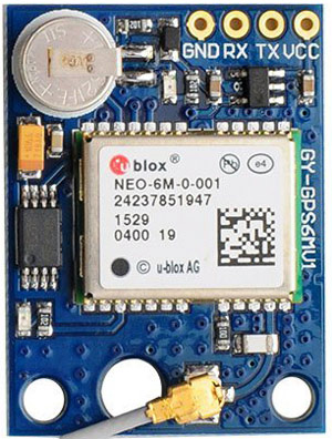
NEO6M GPS Module
Here we are using the NEO6M GPS module. The NEO-6M GPS module is a popular GPS receiver with a built-in ceramic antenna, which provides a strong satellite search capability. This receiver has the ability to sense locations and track up to 22 satellites and identifies locations anywhere in the world. With the on-board signal indicator, we can monitor the network status of the module. It has a data backup battery so that the module can save the data when the main power is shut down accidentally.
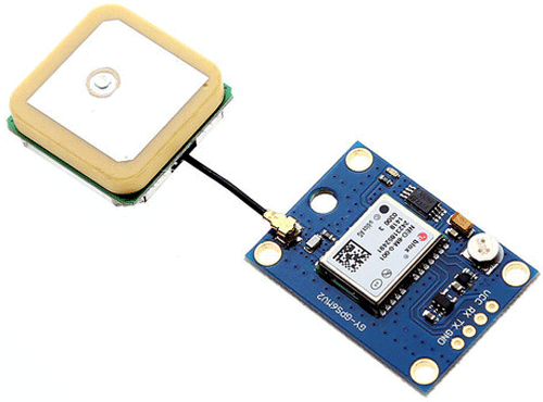
The core heart inside the GPS receiver module is the NEO-6M GPS chip from u-blox. It can track up to 22 satellites on 50 channels and have a very impressive sensitivity level which is -161 dBm. This 50-channel u-blox 6 positioning engine boasts a Time-To-First-Fix (TTFF) of under 1 second. This module supports the baud rate from 4800-230400 bps and has the default baud of 9600.
Features:
- Operating voltage: (2.7-3.6)V DC
- Operating Current: 67 mA
- Baud rate: 4800-230400 bps (9600 Default)
- Communication Protocol: NEMA
- Interface: UART
- External antenna and built-in EEPROM.
Pinout of GPS Module:
- VCC: Input voltage pin of Module
- GND: Ground pin
- RX, TX: UART communication pins with Microcontroller
We have previously interfaced GPS with Arduino and build many projects using GPS modules including vehicle tracking.
1.3 inch I2C OLED Display
The term OLED stands for “Organic Light emitting diode”, it uses the same technology that is used in most of our televisions but has fewer pixels compared to them. It is real fun to have these cool looking display modules to be interfaced with the Arduino since it will make our projects look cool. We have covered a full Article on OLED displays and its types here. Here, we are using a Monochrome 4-pin SH1106 OLED 1.28” OLED display. This Display can only work with the I2C mode.

Technical Specifications:
- Driver IC: SH1106
- Input Voltage: 3.3V-5V DC
- Resolution: 128x64
- Interface: I2C
- Current consumption: 8 mA
- Pixel color: Blue
- Viewing angle: >160 degree
Pin Description:
VCC: Input power supply 3.3-5V DC
GND: Ground reference pin
SCL: Clock pin of the I2C interface
SDA: Serial Data pin of the I2C interface
Arduino community has already given us a lot of Libraries which can be directly used to make this a lot simpler. I tried out a few libraries and found that the Adafruit_SH1106.h Library was very easy to use and had a handful of graphical options, hence we will use the same in this tutorial.
OLED looks very cool and can be easily interfaced with other microcontrollers to build some interesting projects:
- Interfacing SSD1306 OLED Display with Raspberry Pi
- Interfacing SSD1306 OLED Display with Arduino
- Internet Clock using ESP32 and OLED Display
- Automatic AC Temperature Controller using Arduino, DHT11 and IR Blaster
Circuit Diagram
Circuit diagram for this Arduino GPS speedometer using OLED is given below.

The complete setup will look like below:

Programming Arduino for Arduino OLED Speedometer
The complete code of the project is given at the bottom of the tutorial. Here we are explaining the complete code line by line.
First of all, include all the libraries. Here TinyGPS++.h library is used to get the GPS coordinates using GPS receiver module and Adafruit_SH1106.h is used for OLED.
#include <TinyGPS++.h>
#include <SoftwareSerial.h>
#include <Wire.h>
#include <Adafruit_SH1106.h>
Then, the OLED I2C address is defined, which can be either OX3C or OX3D, here it is OX3C in my case. Also, the Reset pin of the display has to be defined. In my case, it is defined as -1, as the display is sharing Arduino’s Reset pin.
#define OLED_ADDRESS   0x3C
#define OLED_RESET -1
Adafruit_SH1106 display(OLED_RESET);
Next, the objects for TinyGPSPlus and Softwareserial class are defined as shown below. Software serial class needs the Arduino pin no. for serial communication, which is defined as 2 and 3 here.
int RX = 2, TX = 3;
TinyGPSPlus gps;
SoftwareSerial gpssoft(RX, TX);
Inside setup(), initialization is done for Serial communication and OLED. The default baud rate for Software serial communication is defined as 9600. Here SH1106_SWITCHCAPVCC is used to generate display voltage from 3.3V internally and display.begin function is used to initialize the display.
void setup()
{
  Serial.begin(9600);
  gpssoft.begin(9600);
  display.begin(SH1106_SWITCHCAPVCC, OLED_ADDRESS);
  display.clearDisplay();
}
Inside while true loop, the serial data received are validated, if valid GPS signals are received, then displayspeed() is called to show the speed value on OLED.
while (gpssoft.available() > 0)
    if (gps.encode(gpssoft.read()))
      displayspeed();
Inside displayspeed() function, the speed data from the GPS module is checked using function gps.speed.isValid() and if it returns a true value, then the speed value is displayed on OLED display. Here the text size on OLED is defined using display.setTextSize function and cursor position is defined using display.setCursor function. The speed data from GPS module is decoded using gps.speed.kmph() function and finally it is displayed using display.display().
if (gps.speed.isValid())
  {
    display.setTextSize(2);
    display.setCursor(40, 40);
    display.print(gps.speed.kmph());
    display.display();
  }
Finally, upload the code in Arduino Uno and put the system in moving vehicle, and you can see the speed on the OLED display as shown in the below image.

Complete code with a demo video is given below. If you are new to GPS module and facing problems in getting this module to work check out the Neo 6M GPs module not working troubleshooting guide article to check out the common problems with this module and how to solve them.
Complete Project Code
#include <TinyGPS++.h>
#include <SoftwareSerial.h>
#include <Wire.h>
#include <Adafruit_SH1106.h>
#define OLED_ADDRESS   0x3C
#define OLED_RESET -1
Adafruit_SH1106 display(OLED_RESET);
int RX = 2, TX = 3;
TinyGPSPlus gps;
SoftwareSerial gpssoft(RX, TX);
void setup()
{
  Serial.begin(9600);
  gpssoft.begin(9600);
  display.begin(SH1106_SWITCHCAPVCC, OLED_ADDRESS);
  display.clearDisplay();
  display.display();
}
void loop()
{
  display.clearDisplay();
  display.setTextSize(1);
  display.setTextColor(WHITE);
  display.setCursor(27, 2);
  display.print("CIRCUIT DIGEST");
  display.setTextSize(1);
  display.setCursor(35, 20);
  display.print("SPEED(KMPH)");
  display.display();
  while (gpssoft.available() > 0)
    if (gps.encode(gpssoft.read()))
      displayspeed();
  if (millis() > 5000 && gps.charsProcessed() < 10)
  {
    display.setTextSize(1);
    display.setCursor(35, 40);
    display.print("Error!!!");
    display.display();
    while (true);
  }
}
void displayspeed()
{
  if (gps.speed.isValid())
  {
    display.setTextSize(2);
    display.setCursor(40, 40);
    display.print(gps.speed.kmph());
    display.display();
  }
  else
  {
    display.setTextSize(1);
    display.setCursor(35, 40);
    display.print("No Data!!!");
    display.display();
  }
  delay(100);
}Comments
I have a similar problem. I'm using a GT_U7 GPS module, and I'm getting the Error!!! message.
Any suggestions?
Nigel
I'm using the same GPS module (GT-U7), I just made this circuit earlier today as I want to use something similar for a project I'm working on.
It does work, however, there are a few errors in the original post.
1. Tx(GPS) needs to go to TX(Arduino) (NOT Rx). Arduino "TX" port is for receiving TX from modules.
2. I also put Rx(GPS) to Rx(Arduino)
3. I found that this portion of the code does nothing beneficial, and seems to hang. So I commented out the following:
//if (millis() > 10000 && gps.charsProcessed() < 5)
{
// display.setTextSize(1);
// display.setCursor(35, 40);
// display.print("Error");
// display.display();
// while (true);
4. Use 3.3v & GND, not 5v. 3.3v -> Vcc(OLED) and Vcc(GPS)
5. Make sure that you have a solid GPS connection. The red light on the GPS module should blink if its connected. If its not blinking, you're not connected to GPS
This should get it working for anyone having trouble
When I verify/compile I get the following message:
Sketch uses 18270 bytes (50%) of program storage space. Maximum is 30720 bytes.
Global variables use 1906 bytes (93%) of dynaqmic memory, leaving 142 bytes for local variable. Maximum is 2048 bytes.
<red text>
Low memory available, stability problems may occur.
Any idea why this would be?
Has anyone else seen this?
Two things to try, I just tested this circuit out earlier today. First, comment out the following lines:
//if (millis() > 10000 && gps.charsProcessed() < 5)
{
// display.setTextSize(1);
// display.setCursor(35, 40);
// display.print("Error");
// display.display();
// while (true);
Removing that worked better for me
If that doesn't work, try a different atmega328p (if using an uno or board with removable atmega), or a different arduino. I do get a low memory available warning also, but it should fit.
Hi,
I`m going to start this projetc soon. I have doubts about powering NEO-6M .
You said its operating voltage is (2.7-3.6)V DC but you are connecting it to 5V Arduino voltage pin (wiring picture above)
I am afraid it may damage NEO-6M module. Maybe it`s better to powering it from 3V3 Arduino pin?
What do you think?
BR,
Marcin
Power it via 3v3. Ive done it this way and it works fine.
No, that NEO-6M sensor works only on 2.7 to 3.6 volt. but here we are using NEO-6m module, in this module we have voltage regulator which converts 5V voltage into 3.3 volt. we are not directly connecting neo-6m sensor with arduio but we are connecting this via module.
What power supply are you using? How many volts?

Hi there,
I'm using a NEO-7M, which I believe is interchangable with the 6M. I can only seem to get the No Data message, and not any kind of speed data itself. Do you have any suggestions I could try please?