

To start with let us understand what these OLED displays mean. The term OLED stands for “Organic Light emitting diode” it uses the same technology that is used in most of our televisions but has fewer pixels compared to them. It is real fun to have these cool looking display modules to be interfaced with the Microcontrollers since it will make our projects look cool.
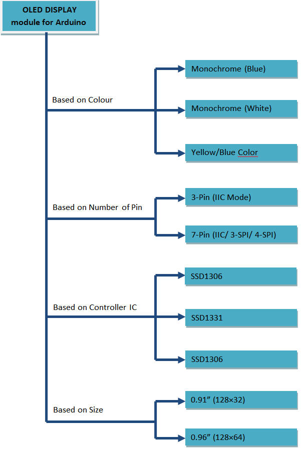
There are a lot of OLED display modules available in the market, each with its own classification. So before you buy one make sure which one would suit your project much better. The most commonly used types are classified below
Before you start working with your OLED display make sure under which category your display fall into. Here we have shown a Monochrome 7-pin SSD1306 0.96” OLED display. This type of display can work on three different communications Protocols such as the SPI 3 Wire mode, SPI four wire mode and IIC mode. SPI 4-wire mode is the fastest mode of communication and the default one.
Pinouts and Function:
As said earlier the module we are using will have 7-pins, the picture of the same is shown below.
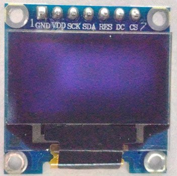
There are lots of vendor for these modules and hence your board might look slightly different than mine. Also the naming might also be differed. The pins and its functions are explained in the table below.
|
Pin Number |
Pin Name |
Other Names |
Usage |
|
1 |
Gnd |
Ground |
Ground pin of the module |
|
2 |
Vdd |
Vcc, 5V |
Power pin (3-5V tolerable) |
|
3 |
SCK |
D0,SCL,CLK |
Acts as the clock pin. Used for both I2C and SPI |
|
4 |
SDA |
D1,MOSI |
Data pin of the module. Used for both IIC and SPI |
|
5 |
RES |
RST,RESET |
Resets the module (useful during SPI) |
|
6 |
DC |
A0 |
Data Command pin. Used for SPI protocol |
|
7 |
CS |
Chip Select |
Useful when more than one module is used under SPI protocol |
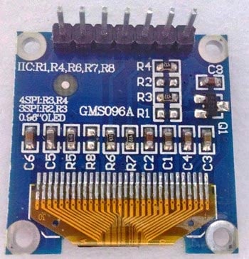
The above shown module can operate in all three modes. When you purchase one, your module will be set to work in 4-Wire SPI mode by default. You can change it to work in I2C or 3-Wire SPI by changing the position of the Resistors as shown in the Bottom Layer silkscreen of the board.
Working of an OLED display:
In order to make something appear on the OLED screen we communicate with the SSD1306 IC present in the OLED module. This SSD1306IC will then update each pixel present on our OLED display.
This communication can happen via IIC or SPI from any Microcontrollers like Arduino, PIC, etc. In order to communicate with an IC through any of the communication protocol we should first understand the IC by reading its datasheet which is a tiring but useful method. Here we have interfaced OLED with Arduino.
There are lot of Libraries available for interfacing it with different Microcontrollers, using which we can make the interfacing a lot simpler. These libraries are easy to use and have lot of readily available graphical options. Also there are many online tools available for converting an image into a bit map values to be fed into microcontrollers. Like we have created below Batman logo with Arduino using this webtool:
![]()

VERY cool Site!
Have you connected to d1 mini or nodemcu u with 0.96 in or 0.66 oled shield? If not can you steer me to sites that do? How about i2c 4 pin displays?
Thanks again