

In the vast system of embedded applications, no microcontroller can perform all the activities by itself. At some stage of time, it has to communicate to other devices to share information, there are many different types of communication protocols to share these informations, but the most used ones are USART, IIC, SPI, and CAN. Each communication protocol has its own advantage and disadvantage. Let’s focus on the IIC part for now since that is what we are going to learn in this tutorial. If you are new here, do check out the Nuvoton Tutorials where we have discussed every peripheral of the N76E003 Microcontroller from the very basic getting started tutorial. If you want to learn how to use I2C with other microcontrollers, you can check out the links below.
- How to use I2C in Arduino: Communication between two Arduino Boards
- I2C Communication with PIC Microcontroller PIC16F877
- Interfacing 16X2 LCD with ESP32 using I2C
- I2C communication with MSP430 Launchpad
- Interfacing LCD with NodeMCU without using I2C
- How to handle multi communications (I2C SPI UART) in a single program of Arduino
I2C is an important communication protocol that is developed by Philips (now NXP). Using this I2C protocol, an MCU can be connected with multiple devices and start communication. I2C works with only two wires, namely SDA and SCL. Where SDA stands for Serial data and SCL stands for Serial Clock. However, these two pins require pull-up resistors to the VCC voltage level and with an adequate pull-up resistor, the bus could support 127 devices with a unique address.
What is I2C Communication Protocol?
The term IIC stands for “Inter Integrated Circuits”. It is normally denoted as I2C or I squared C or even as 2-wire interface protocol (TWI) at some places but it all means the same. I2C is a synchronous communication protocol meaning, both the devices that are sharing the information must share a common clock signal. It has only two wires to share information out of which one is used for the clock signal and the other is used for sending and receiving data.
How I2C Communication Works?
I2C communication was first introduced by Phillips. As said earlier, it has two wires, these two wires will be connected across two devices. Here one device is called a master and the other device is called a slave. Communication should and will always occur between two, a Master and a Slave. The advantage of I2C communication is that more than one slave can be connected to a Master.
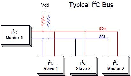
The complete communication takes place through these two wires namely, Serial Clock (SCL) and Serial Data (SDA).
Serial Clock (SCL): Shares the clock signal generated by the master with the slave
Serial Data (SDA): Sends the data to and from between the Master and slave.
At any given time, only the master will be able to initiate the communication. Since there is more than one slave in the bus, the master has to refer to each slave using a different address. When addressed only the salve with that particular address will reply back with the information while the others keep quiet. This way, we can use the same bus to communicate with multiple devices.
Where to Use I2C Communication?
I2C communication is used only for short distance communication. It is certainly reliable to an extent since it has a synchronized clock pulse to make it smart. This protocol is mainly used to communicate with the sensor or other devices which has to send information to a master. It is very handy when a microcontroller has to communicate with many other slave modules using a minimum of only wires. If you are looking for long-range communication, you should try RS232 and if you are looking for more reliable communication, you should try the SPI protocol.
I2C on Nuvoton N76E003 - Hardware Requirement
As the requirement of this project is to learn I2C communication using N76E003, we will use an EEPROM which will be connected with the I2C data line. We will store some data into the EEPROM and also read the same and display it using the UART screen.
As the stored value will be printed in the UART, any kind of USB to UART converter is required. You can also check out the tutorial on UART with Nuvoton if you are new to UART communication on N76E003. For our application, we will use CP2102 UART to USB converter. Other than the above, we also require the following components-
- EEPROM 24C02
- 2pcs 4.7k resistors
Not to mention, other than the above components, we need an N76E003 microcontroller based development board as well as the Nu-Link Programmer. Additionally, breadboard and hookup wires are also required for connecting all components.
Interfacing AT24LC64 with Nuvoton N76E003 – Circuit Diagram
As we can see in the schematic below, the EEPROM is connected in the I2C line along with two pull up resistors. On the extreme left, the programming interface connection is shown.

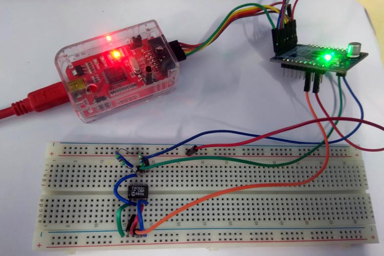
I used a breadboard for the AT24LC64 IC and connected the IC to my nuvoton programmer board using jumper wires. My hardware setup along with the nu-ink programmer is shown below.

I2C Pins on Nuvoton N76E003
The pin diagram of N76E003 can be seen in the below image-
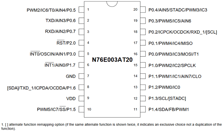
As we can see, each pin has different specifications and each pin can be used for multiple purposes. However, pin 1.4 is used as an I2C SDA pin, it'll lose the PWM and other functionality. But that is not a problem as another functionality is not required for this project. The same thing will happen for the P1.3 is the SCL pin of I2C.
Since I2C pins act as a GPIO, it needs to be configured. All GPIO pins can be configured in the below-described mode.
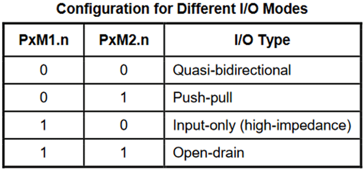
As per the datasheet, PxM1.n and PxM2.n are two registers that are used to determine the control operation of the I/O port. In the datasheet, it is stated that to use the I2C functionality, the I/O modes need to be used as Open-drain for I2C related communications.
I2C Communication in N76E003
The I2C peripheral is an important thing for any microcontroller unit that supports I2C features. Many types of different microcontrollers come with an in-built I2C peripheral. However, in some cases, I2C can be configured manually using software control where I2C related hardware support is not available (For example, many 8051 microcontrollers). However, the nuvoton N76E003 comes with I2C peripheral support.
M76E003 supports four types of operations in I2C modes - Master Transmitter, Master Receiver, Slave Transmitter, and Slave Receiver. It also supports standard (100kbps) and fast (up to 400kbps) speeds for the I2C line. I2C works with few generic rules in the SCL and SDA signal lines.
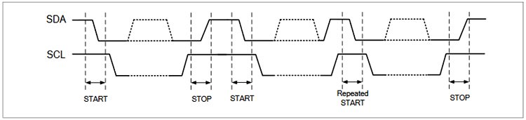
Start and Stop Condition:
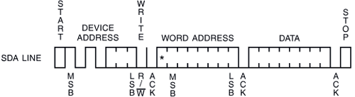
It is an important thing in I2C communication. When data is transferred to the I2C line, it starts with begin condition and ends with a stop condition.
The start condition is the high-to-low transition on the SDA when the SCL line is high and the stop condition is the low-to-high transition on the SDA when the SCL line is high. These two conditions are generated by the master (The MCU or anything that is controlling the other slave devices). The bus line remains busy at this state when the start condition is initiated and remains free again when the stop condition is initiated.
The Start and Stop condition is excellently shown in the signal perspective in the N76E003 datasheet-
7-Bit Address with Data Format:
N76E003 supports a 7-bit address and data format. After the start condition is initiated, the master device needs to send the data to the I2C line. The first data is an important one. If this data is not properly created or transmitted, the connected device will not be identified and further communications cannot be made.
The data consists of a 7-bit long slave address, denoted as SLA. This 7-bit long address needs to be unique for each device if multiple devices are connected on the bus. After the 7-bit address, the 8th bit is the data direction bit. That means, depending on the 8th bit, the master sends the information to the slave device about whether data will be written in the slave device or the data will be read from the slave device. The 8th bit is the R/W bit referred to as Read or Write notifier. As we all know 8-bit information can be 128 types, thus supporting 128 devices, but I2C supports 127 types of devices on the same bus but not 128. Because the 0x00 address is a reserved address which is called a general call address. If the master wants to send information to all devices, it will address 0x00 and each device will replay in the same manner as per the individual software configurations.
Thus, the data transmission looks like below-
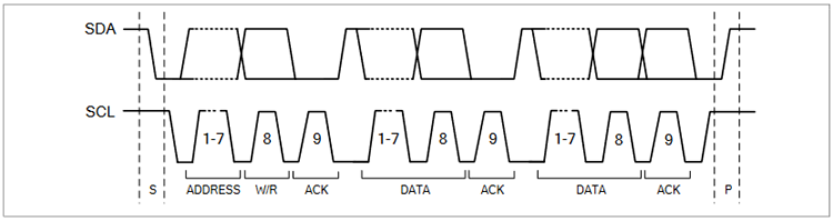
Acknowledge:
In the above data address image, the 9th bit followed by the R/W bit is called the acknowledge bit. It is an important one because using this bit, the master or slave responds to the data transmitter by pulling the SDA line low. To get the acknowledge bit, the transmitter needs to release the SDA line.
Programming N76E003 for I2C Communication
The complete program used in this tutorial can be found at the bottom of this page. The explanation of important segments in the code is as follows-
Set Pins as Open Drain and Configure them for I2C:
Let's start with the I2C pin section first. As described before, the I2C SCL and SDA ports need to be configured and set as the open-drain configuration. To do this, we are using an I2C.h header file along with an I2C.c source file. The code snippet looks like this-
do {P13_OpenDrain_Mode; P14_OpenDrain_Mode; clr_I2CPX;}while(0)
The above code is setting the P13 and P14 as Open-Drain pin and clr_I2CPX is used to select the P13 and P14 as SCL pin on P1.3 and SDA pin on P1.4.
This I2CPX is the 0th bit of I2C control register I2CON. If this I2C_PX is set as 1, the pins are changed to P0.2 as SCL and P1.6 as SDA. However, we will use P13 and P14. Alternative pins are not used here.
I2C Control Register I2CON:
I2C control register I2CON is used to control the I2C operations. The first bit is the I2C pin selection bit. Setting it 0 configures the I2C pin as P13 and P14.
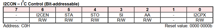
AA bit is the Acknowledge assert flag, if the AA flag is set, an ACK will be returned during the acknowledge clock pulse of the SCL line. If it is cleared, a NACK (high level on SDA) will be returned during the acknowledged clock pulse of the SCL line.
The next bit is SI which is the I2C status interrupt. If I2C Status Interrupt is enabled, the user should check the I2STAT register to determine which step has been passed and should take the action.
The STO is the STOP flag being set in master mode. STO is automatically cleared by hardware once the STOP condition has been detected.
The next bit is the STA bit. If this flag is set, then I2C generates a START condition if the bus is free. If the bus is busy, the I2C waits for a STOP condition and generates a START condition following. If STA is set while the I2C is already in the master mode and one or more bytes have been transmitted or received, the I2C generates a repeated START condition. The STA needs to be cleared manually by the software.
The last one, I2CEN is the I2C bus enable or disable bit.
EEPROM 24C02:
Now, coming to the 24C02. The board support package of N76E003 has an I2C code for the 24LC64 and can be modified easily. However, we will use a simple method to understand the I2C function.
If anybody wants to use detailed interfacing with EEPROM 24C02, then the EEPROM program in the BSP can be used.
We will only connect the 24C02 in I2C where the N76E003 will be master and the EEPROM will be a slave. Thus, we will write any data into the EEPROM address and read the same.
24C02 EEPROM pinout is shown below-
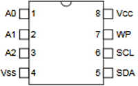
A0, A1, and A2 are three address selection pins. The WP pins are Write protect pins and need to be connected with VSS for enabling writing to in the EEPROM.
The Byte Write functionality is shown in the below image-
The full write cycle happens with a start bit. After that, the Control byte needs to be submitted. In the control byte, the following things are required-
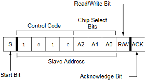
After the start bit, consist of the slave address. 1010 is the static and A0, A1, and A2 are the hardware connection based address. If the three pins are connected with GND or VSS supply, it will be read as 0. Otherwise, if connected with VCC, it will be read as 1. In our case, all A0, A1, and A2 are connected with VSS. Thus all these will be 0.
Spending on the read or write condition. The value of the address with the Read or Write bit will be - 0xA0 for Write and 0xA1 for reading. Next is the Acknowledge bit and after that, an 8-bit address will be transmitted where the data needs to be stored and finally, the data that will be stored in the respective location. These things are done in a step by step format in the main function.
Main Function and While Loop:
void main(void)
{
                 char c=0x00;
                 InitialUART0_Timer3(115200);
                  TI = 1;   // Important, use prinft function must set TI=1;
                I2C_init();
                while(1)
                {
                                 EEPROM_write(1,0x55);
                c = EEPROM_read(1);
                                 printf ("\n The value read is %x", c & 0xff);
                };
}
The main function is simple, it is continuously writing values to the EEPROM in the address 1 and reading the data. The data is then getting printed using the printf function. The printf is printing the value in hex.
The EEPROM write function consists of the following things that were described in the EEPROM section-
void EEPROM_write(unsigned char address, unsigned char value)
{
            I2C_start();
            I2C_write(0xA0);
            I2C_write(address);
            I2C_write(value);
            I2C_stop();
}
The I2C start function consists of the following things-
void I2C_start(void)
{
            signed int time = timeout;
            set_STA;
            clr_SI;
            while((SI == 0) && (time > 0))
            {
            time--;
            };
}
In this function, the SI status is being checked along with the predefined timeout period (defined in I2C.h where the predefined time is set as 1000). The start function begins with setting the STA and clearing the SI.
void I2C_stop(void)
{
            signed int time = timeout;
            clr_SI;
            set_STO;
            while((STO == 1) && (time > 0))
            {
            time--;
            };
}
Same as the Start, stop function is used. The stop function is initiated by setting up the STO followed by clearing the SI. Below function is the I2C read function-
unsigned char I2C_read(unsigned char ack_mode)
{
            signed int time = timeout;
            unsigned char value = 0x00;
            set_AA;
            clr_SI;
            while((SI == 0) && (t > 0))
            {
            time--;
            };
            value = I2DAT;
            if(ack_mode == I2C_NACK)
            {
            t = timeout_count;
            clr_AA;
            clr_SI;
            while((SI == 0) && (t > 0))
            {
            time--;
            };
            }
            return value;
}
The ack_mode and I2C_NACK, both are defined in the I2C header file as 0 and 1 respectively.
Similarly, the write function is created-
void I2C_write(unsigned char value)
{
            signed int time = timeout;
            I2DAT = value;
            clr_STA;
            clr_SI;
            while((SI == 0) && (time > 0))
            {
            time--;
            };
}
Flashing the Code and the Output
The code returned 0 warning and 0 Errors and was flashed using the default flashing method by the Keil. If you are new, check out the getting started with nuvoton tutorial to understand how to upload code. The compiling information of the code can be found below.
Build target 'I2C_EEPROM'
compiling I2C_EEPROM.c...
compiling I2C.c...
linking...
Program Size: data=59.2 xdata=0 code=2409
creating hex file from ".\Output\I2C_EEPROM"...
".\Output\I2C_EEPROM" - 0 Error(s), 0 Warning(s).
Build Time Elapsed:  00:00:04
Batch-Build summary: 1 succeeded, 0 failed, 0 skipped - Time Elapsed: 00:00:04
The hardware is being set up on a breadboard and is working as expected. As you can see in the image below, we were able to write a value on EEPROM and read it back from the memory and display it on the serial monitor.
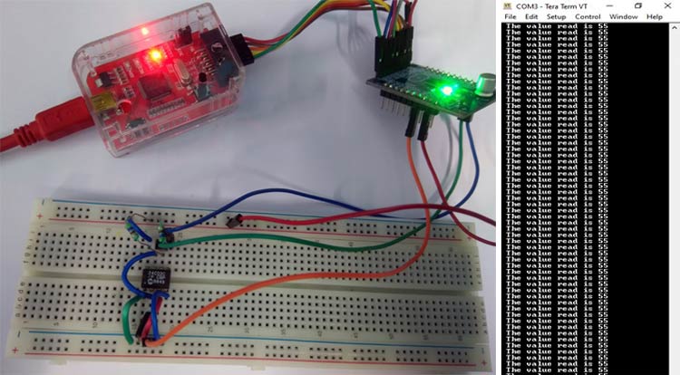
Check out the video given below for a complete demonstration of how the board works for this code. Hope you enjoyed the tutorial and learned something useful if you have any questions, leave them in the comment section below. You can also use our forums to post other technical questions.
Complete Project Code
#include "N76E003.h"
#include "SFR_Macro.h"
#include "Function_define.h"
#include "Common.h"
#include "Delay.h"
#include "I2C.h"
#define I2C_W                           0
#define I2C_R                            1
unsigned char EEPROM_read(unsigned char address);
void EEPROM_write(unsigned char address, unsigned char value);
void EEPROM_write(unsigned char address, unsigned char value)
{
            I2C_start();
            I2C_write(0xA0);
            I2C_write(address);
            I2C_write(value);
            I2C_stop();
}
unsigned char EEPROM_read(unsigned char address)
{
            unsigned char value = 0x00;
            I2C_start();
            I2C_write(0xA1);
            I2C_write(address);
            I2C_start();
            I2C_write(0xA1);
            value = I2C_read(I2C_NACK);
            I2C_stop();
            return value;
}
void main(void)
{
             char c=0x00;
             InitialUART0_Timer3(115200);
TI = 1;    // Important, use prinft function must set TI=1;
            I2C_init();
            while(1)
            {
             EEPROM_write(1,0xC0);
            c = EEPROM_read(1);
             printf ("\n The value read is %x", c & 0xff);
            };
}Comments
sir, i have problem in
sir, i have problem in
signed int time = timeout;
t = timeout_count;
please give me solution
Hello Sir/Mam,
Hello Sir/Mam,
Can u just provide the I2C.h file??
Thank You.
Hello Sir,
Hello Sir,
Can you show us an example where N76E003 act as a slave to arduino as the master with thanks.
Thank you for your attention
Dang Dinh Ngoc

I HAVE PROBLEM Interfacing AT24C02 EEPROM with Nuvoton N76E003
Build started: Project: UART
Build target 'UART'
compiling main.c...
main.c(6): warning C318: can't open file 'I2C.h'
main.c(40): error C202: 'timeout': undefined identifier
main.c(51): error C202: 'timeout': undefined identifier
main.c(62): error C202: 'timeout': undefined identifier
main.c(66): error C202: 't': undefined identifier
main.c(71): error C202: 'I2C_NACK': undefined identifier
main.c(73): error C202: 't': undefined identifier
main.c(76): error C202: 't': undefined identifier
main.c(86): error C202: 'timeout': undefined identifier
main.c(112): error C202: 'I2C_NACK': undefined identifier
Target not created.
Build Time Elapsed: 00:00:01
THIS ERROR MASSAGE