

UART stands for Universal Asynchronous Receiver/Transmitter and it is a useful hardware feature in any microcontroller unit. A microcontroller needs to receive data, process it, and send it to the other devices. There are different types of communication protocols available in the microcontroller, however, UART is the most used one among the other communication protocols like SPI and I2C. If someone needs to receive or transmit data serially, UART is always the simplest and common option. The advantage of UART is it only requires two wires to transmit data between devices. Continuing with our Nuvoton Microcontroller Tutorial, in this article, we will learn how to perform serial communication using the N76E003 microcontroller.
Basics of UART Communication
Now, as we know what UART is, it is important to know the associated parameters of the UART.
Two UART devices receive and transmit data at the same frequency. When the receiving UART device detects a start bit, it starts to read the incoming bits at a specific frequency known as the baud rate. Baud rate is an important thing for UART communication and it is used to measure the speed of data transfer in bits per second (bps). This baud rate speed, for the transmit and receive, must be at the same baud rate. The baud rate speed difference between the transmitting and receiving UARTs can only be about 10% before the timing of bits gets too far off. Most popular baud rate speeds are 4800, 9600, 115200 bps, etc. Previously we have used UART communication in many other microcontrollers as well that are listed below.
- UART Communication between ATmega8 and Arduino Uno
- UART Communication between Two ATmega8 Microcontrollers
- UART Communication using PIC Microcontrollers
- UART Communication on STM8S Microcontroller
The N76E003 has two UARTs - UART0 and UART1. In this tutorial, we will use the UART peripheral on N76E003 microcontroller unit. Without wasting much time, let's evaluate what kind of hardware setup we require for this application.
Hardware Requirement and Setup
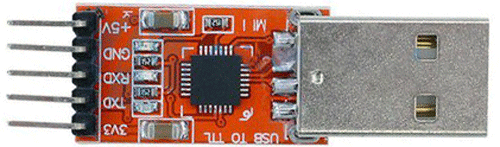
The major component that is required for this project is the USB to UART or TTL converter module that will make the interface required between the PC or Laptop with the microcontroller module. For this project, we will use CP2102 based USB to UART module that is shown below.
Not to mention, other than the above component, we need the N76E003 microcontroller based development board as well as the Nu-Link Programmer. An additional 5V power supply unit may be required if the programmer is not used as a power source.
Circuit Diagram for Nuvoton N76E003 UART Communication
As we can see in the below development board schematic, the 2nd and 3rd pin of the microcontroller unit is used as a UART0 Tx and Rx respectively. On the extreme left, the programming interface connection is shown.

UART Pins on Nuvoton N76E003 Microcontroller
The N76E003 has 20 pins out of which 4 pins can be used for UART communication. The below image is showing the UART pins highlighted in a red square box (Rx) and Blue square box (Tx).
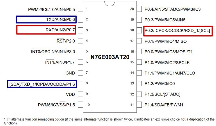
For the UART0, pin 2 and 3 are used for UART communication, and for the UART1, pin 8 and pin 18 is used for communication.
UART Registers in Nuvoton N76E003 Microcontroller
N76E003 has two enhanced full-duplex UARTs with automatic address recognition and framing error detection - UART0 and UART1. These two UARTs are controlled using registers categorized into two different UARTs. There are two pairs of RX and TX pins available in N76E003 for UART operations. Thus the first step is to select the desired UART port for operations.
In this tutorial, we will use the UART0, thus the configuration will be shown for the UART0 only. UART1 will have the same configuration but the registers will be different.
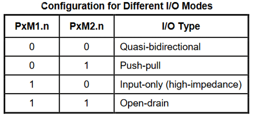
After selecting one UART (UART0 in this case), the I/O pins that are needed to be used for RX and TX communication needs to be configured as input and output. The RX pin of UART0 is pin 3 of the microcontroller that is Port 0.7. As this is a serial port receive pin, the Port 0.7 is needed to be set as input. On the other hand, the Port 0.6 which is the 2nd pin of the microcontroller is a transmit pin or output pin. It needs to be set as a Quasi bidirectional mode. These can be selected using the PxM1 and PxM2 register. These two registers set the I/O modes where the x stands for the Port number (For example, Port P1.0 the register will be P1M1 and P1M2, for P3.0 it will be P3M1 and P3M2, etc.) The configuration can be seen in the below image-
UART Operating Modes in N76E003
Then, the next step is to determine the mode of UART operations. The two UARTs could operate in 4 modes. The modes are-
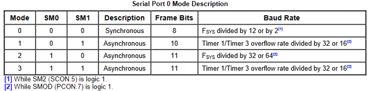
As we can see, the SM0 and SM1 (7th and 6th bit of SCON register) select the mode of UART operations. Mode 0 is the synchronous operation and the other three modes are asynchronous operations. However, the Baud Rate generator and the Frame bits are different for each serial port mode. Anyone of the modes can be selected as per application requirement and this is the same for the UART1 also. For this tutorial, 10 bits operation with timer 3 overflow rate divided by 32 or 16 is used.
Now, it is time to get information and configure the SCON register (SCON_1 for UART1) for UART0.
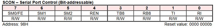
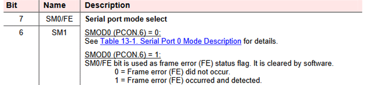
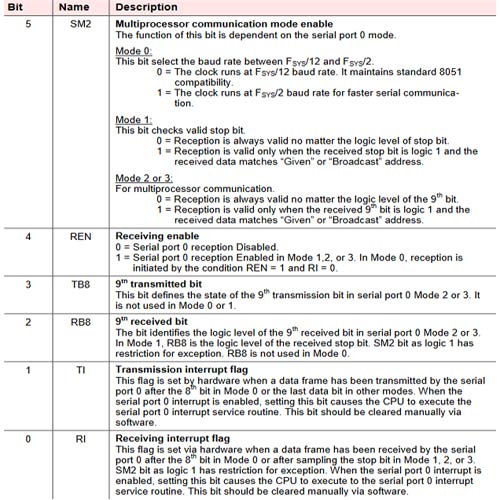
The 6th and 7th bit will set the UART mode as discussed previously. Bit 5 is used to set the Multiprocessor communication mode to enable options. However, the process is dependent on which UART mode is selected. Other than these, the REN bit will be set to 1 to enable reception and the TI flag will be set to 1 for printf function to be used instead of custom UART0 transmit function.
The next important register is the Power control register (PCON) (Timer 3 bit 7 and 6 for UART1) register. If you are new to timers, check out the Nuvoton N76E003 Timer tutorial to understand how to use timers on N76E003 Microcontroller.
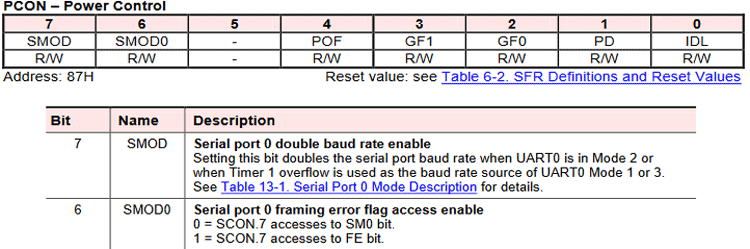
The SMOD bit is important to select the double baud rate in UART0 mode 1. Now, as we are using the timer 3, the Timer 3 control register T3CON needs to be configured. However, the bit 7th and 6th are reserved for the double data rate setting for UART1.
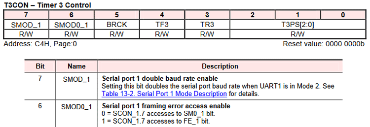
And the Timer 3 pre-scaler value-
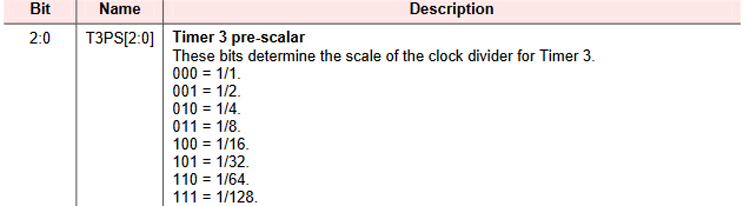
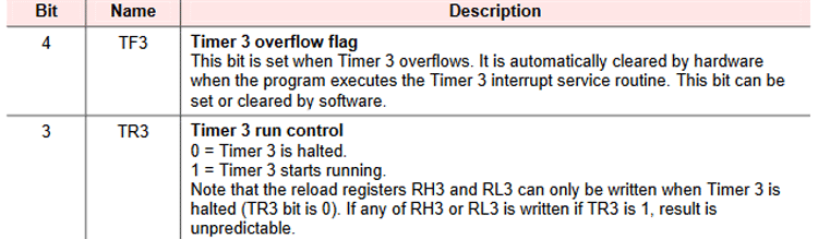
The 5th bit BRCK will set the Timer 3 as the baud rate clock source for UART1. Now, the datasheet of N76E003 is given the formula for calculating the desired Baud rate as well as sample set value for the Timer 3 (16-bits) High and Low registers.
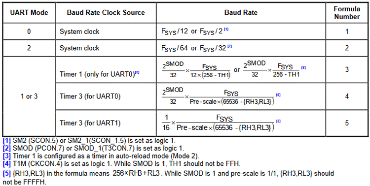
Sample value for 16 Mhz clock source-
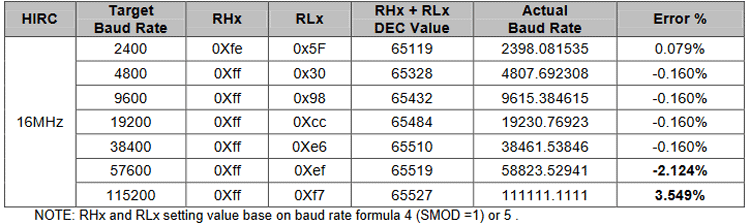
Thus the baud rate needs to be configured in the Timer 3 register using the above formula. For our case, it will be the Formula 4. After that, starting the Timer 3 by setting the TR3 register to 1 will finish the UART0 Initialization Timer 3. To receive and sent the UART0 data to use the below register-
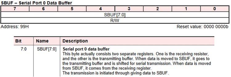
The SBUF register automatically gets configured for Receive and Transmit. To receive data from the UART, wait for the RI flag to set 1 and read the SBUF register and to send the data to UART0, send the data to SBUF and wait for the TI flag to get 1 to confirm successful data transmission.
Programming Nuvoton N76E003 for UART Communication
The coding part is simple and the complete code used in this tutorial can be found at the bottom of this page. The explanation of the code is as follows, The UART0 is initialized at 9600 baud rates using the statement in the main function-
InitialUART0_Timer3(9600);
The above function is defined in the common.c file and it is configuring the UART0 with Timer 3 as the baud rate source, in mode 1, and with a baud rate of 9600. The function definition is as follows-
void InitialUART0_Timer3(UINT32 u32Baudrate) //use timer3 as Baudrate generator
{
 P06_Quasi_Mode;    //Setting UART pin as Quasi mode for transmit
 P07_Input_Mode;   //Setting UART pin as input mode for recieve
 SCON = 0x50;      //UART0 Mode1,REN=1,TI=1
 set_SMOD;        //UART0 Double Rate Enable
 T3CON &= 0xF8;  //T3PS2=0,T3PS1=0,T3PS0=0(Prescale=1)
 set_BRCK;      //UART0 baud rate clock source = Timer3
#ifdef FOSC_160000
RH3= HIBYTE(65536 - (1000000/u32Baudrate)-1);      /*16 MHz */
RL3= LOBYTE(65536 - (1000000/u32Baudrate)-1);     /*16 MHz */
#endif
#ifdef FOSC_166000
  RH3= HIBYTE(65536 - (1037500/u32Baudrate));      /*16.6 MHz */
  RL3 = LOBYTE(65536 - (1037500/u32Baudrate));     /*16.6 MHz */
#endif
 set_TR3;      //Trigger Timer3
 set_TI;     //For printf function must setting TI = 1
}
The declaration is done step by step as discussed before and the registers are configured accordingly. However, in the BSP library of the N76E003, there is a bug that is instead of P07_Input_Mode; there is P07_Quasi_Mode. Due to this, the UART Receive function will not work.
The Baud rate is also configured as per the baud rate input and using the formula given by the datasheet. Now, in the main function or the while loop, the printf function is used. To use the printf function, The TI needs to be set as 1. Other than this, in the while loop, a switch case is used and as per the UART data received, the value is printed.
while(1)
       {
        printf("\r\nPress 1 or Press 2 or Press 3 or Press 4");
        oper = Receive_Data_From_UART0();
        switch (oper) {
        case '1':
        printf("\r\n1 is pressed");
        break;
        case '2':
        printf("\r\n2 is pressed");
        break;
        case '3':
        printf("\r\n3 is pressed");
        break;
        case '4':
        printf("\r\n4 is pressed");
        break;
        default:
        printf("\r\nWrong key pressed");
   }
        Timer0_Delay1ms(300);
 }
}
Well, for the UART0 receive the Receive_Data_From_UART0(); function is used. It is also defined in the common.c library.
UINT8 Receive_Data_From_UART0(void)
{
 UINT8 c;
 while (!RI);
 c = SBUF;
 RI = 0;
 return (c);
}
It will wait for the RI flag to get 1 and return the receive data using the variable c.
Flashing the Code and Output
The code returned 0 warning and 0 Errors and flashed using the default flashing method by the Keil. If you are not sure how to compile and upload code, check out the getting started with nuvoton article. The below lines confirm that our code has been uploaded successfully.
Rebuild started: Project: printf_UART0
Rebuild target 'GPIO'
compiling PUTCHAR.C...
compiling Print_UART0.C...
compiling Delay.c...
compiling Common.c...
assembling STARTUP.A51...
linking...
Program Size: data=54.2 xdata=0 code=2341
creating hex file from ".\Output\Printf_UART1"...
".\Output\Printf_UART1" - 0 Error(s), 0 Warning(s).
Build Time Elapsed:  00:00:02
Load "G:\\n76E003\\software\\N76E003_BSP_Keil_C51_V1.0.6\\Sample_Code\\UART0_Printf\\Output\\Printf_UART1"
Flash Erase Done.
Flash Write Done: 2341 bytes programmed.
Flash Verify Done: 2341 bytes verified.
Flash Load finished at 15:48:08
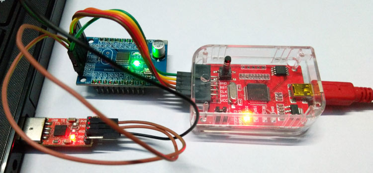
The Development board is connected in the power source through the programmer and the laptop using the USB to UART module. To display or to send the UART data, a serial monitor software is required. I am using tera term for this process.
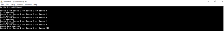
As you can see in the below image, I was able to display the strings sent from our nuvoton controller and display it on the serial monitor software. Also was able to read values from the serial monitor.
You can check out the video linked below for the complete demonstration of this tutorial. Hope you enjoyed the article and learned something useful. If you have any questions, you can leave them in the comment section below or use our forums to post other technical questions.
Complete Project Code
#include "N76E003.h"
#include "SFR_Macro.h"
#include "Function_define.h"
#include "Common.h"
#include "Delay.h"
/*==========================================================================*/
void main (void)
{
             char oper;
             InitialUART0_Timer3(9600);
      TI = 1;       // prinft function is used.
             printf("Hello CircuitDigest\r\n");
             while(1)
             {
                         printf("\r\nPress 1 or Press 2 or Press 3 or Press 4");
                                     oper = Receive_Data_From_UART0();
            switch (oper) {
            case '1':
            printf("\r\n1 is pressed");
            break;
            case '2':
            printf("\r\n2 is pressed");
            break;
            case '3':
            printf("\r\n3 is pressed");
            break;
            case '4':
            printf("\r\n4 is pressed");
            break;
            default:
            printf("\r\nWrong key pressed");
            }
                         Timer0_Delay1ms(300);
             }
}
Hai, How to Read string value from UART0 @115200 baud Rate, for example
"relay1on"
"relay2on"
"relay1off"
"relay2off"
can you please help with this ??
please share the project file if possible to [email protected], it's little urgent task for me, I have been stuck in this from last week, please help