
GSM Modules are frequently used in IoT projects since it has the ability to send and receive data remotely. The GSM Modules doesn’t have much dependencies like the Wi-Fi modules. While other wireless modules such Wi-Fi or Zigbee have cons such as short range and cost, the GSM Module have the reliability, long range Since only one SIM card is required with valid plan. Though the GSM modules cannot send a vast amount of data generated by sensors, it is ideal for applications where small reasonable amount of data to be sent.
In this tutorial, such GSM module will be interfaced with STM32F103C8 ARM microcontroller to send and receive Text Messages (SMS) from the cellular mobile number configured in the program. To display the messages received and sent, one 16x2 LCD will be used with two Push Buttons which will initiate sending and receiving of text messages after pressing the relative button.
There are already several GSM projects are available interfaced with different kind of microcontrollers. You can go and check all the GSM Projects here, and try DIY by referencing previous tutorials on different GSM modules such as SIM900, SIM900A, SIM800, etc. Some of the projects with GSM modules are given below:
- Call and Message using Arduino and GSM Module
- Wireless Notice Board using GSM and Arduino
- Interfacing GSM Module with AVR Microcontroller: Send and Receive Messages
- GSM Module Interfacing with 8051 Microcontroller
- Arduino Based Vehicle Accident Alert System using GPS, GSM and Accelerometer
Components Required
- STM32F103C8 Cortex-M3 Microcontroller
- GSM Module (SIM800C is used in the tutorial)
- 16x2 LCD Display
- Push Buttons (2)
- 10k Potentiometer
- Breadboard
- Connecting Wires
What is SIM800C GSM Module?
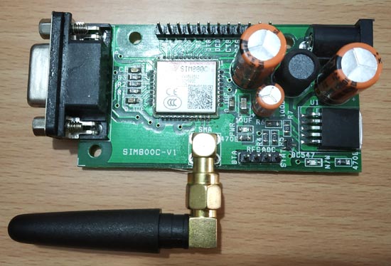
SIM800C is a widely used GSM Module with a serial interface modem which runs in between 3.4V-4.4V Voltage level. SIM800C is a Quad-band GSM/GPRS Module which is used in embedded applications where the remote data transfer is required. SIM800C works on 850/900/1800/1900MHz. It can also receive & transmit Voice Call, SMS with low power consumption. The module is controlled by using AT commands. It supports one SIM card interface and has UART (TX & RX) pins along with one RS232 Serial Protocol that can be used to interface with different microcontrollers in embedded applications.
Powering SIM800C GSM Module
A DC Power adapter of 12V is used to power the SIM800C GSM module.
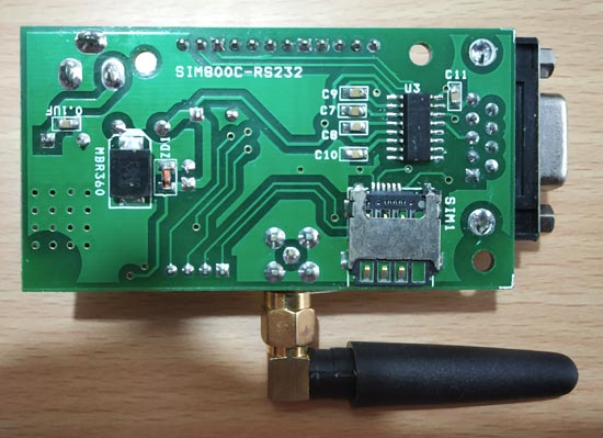
Inserting SIM in SIM800C GSM Module
A SIM card is inserted at the back of the SIM800C GSM module. Note that the SIM800C doesn’t support 4G, so do not insert a 4G SIM Card.
Interfacing GSM SIM800C with STM32F103C8
In order to interface SIM800C with STM32F103C8 microcontroller, the UART Serial port will be used which is a hardware serial interface of the STM32F103C8. The below image indicates the UART pins in STM32F103C8 which are A9 and A10.

The STM32F103C8 has three UART interface for connecting three external serial peripherals.
AT Commands
The AT-commands will be used to access the functions of GSM Module such as sending and receiving Voice Calls, Text Messages. Some of the AT commands are given below which will be important in this tutorial and will be used frequently.
|
AT |
Replies with OK for Acknowledgement |
|
AT+CPIN? |
Check signal Quality |
|
AT+COPS? |
Find service provider name |
|
ATDXXXXXXXXXX; |
Call to the specific number, ends with semi-colon,replace X with mobile number |
|
AT+CNUM |
Find the number of SIM card (might not work for some SIM) |
|
ATA |
Answer the Incoming Call |
|
ATH |
Hang off the current Incoming call |
|
AT+COLP |
Show incoming call number |
|
AT+VTS=(number) |
Send DTMF number. You can use any number on your mobile keypad for (number) |
|
AT+CMGR |
AT+CMGR=1 reads message at first position |
|
AT+CMGD=1 |
Delete message at first position |
|
AT+CMGDA=”DEL ALL” |
Delete All messages from SIM |
|
AT+CMGL=”ALL” |
Read all messaged from SIM |
|
AT+CMGF=1 |
Set SMS configuration. “1” is for text only mode |
|
AT+CMGS = “+91 XXXXXXXXXX” >CircuitDigest Text<Ctrl+z> |
Sends SMS to a particular number here XXXXXXXXXX. When you see “>” start entering the text. Press Ctrl+Z to send the text. |
|
AT+CNMI=2,2,0,0,0 |
To receive Live SMS |
|
AT+CGATT? |
To check for internet connection on SIM card |
|
AT+CIPSHUT |
To close TCP connection, meaning to disconnect form internet |
|
AT+CSTT = “APN”,”username”,”Pass” |
Connect to GPRS with your APN and Pass key. Can be obtained from Network Provider. |
|
AT+CIICR |
Check if SIM card has data pack |
|
AT+CIFSR |
Get IP of the SIM network |
|
AT+CIPSTART = “TCP”,”SERVER IP”,”PORT” |
Used to set a TCP IP connection |
|
AT+CIPSEND |
This command is used to send data to server |
Circuit Diagram
Connections for connecting GSM with STM32 is shown in the circuit diagram below.

Circuit connections between STM32F103C8 & GSM SIM800C
|
STM32F103C8 |
GSM SIM800C |
|
PA9 (TX) |
RX |
|
PA10 (RX) |
TX |
|
GND |
GND |
Circuit connections between STM32F103C8 & 16x2 LCD
|
LCD Pin No |
LCD Pin Name |
STM32 Pin Name |
|
1 |
Ground (Gnd) |
Ground (G) |
|
2 |
VCC |
5V |
|
3 |
VEE |
Pin from Centre of Potentiometer for contrast |
|
4 |
Register Select (RS) |
PB11 |
|
5 |
Read/Write (RW) |
Ground (G) |
|
6 |
Enable (EN) |
PB10 |
|
7 |
Data Bit 0 (DB0) |
No Connection (NC) |
|
8 |
Data Bit 1 (DB1) |
No Connection (NC) |
|
9 |
Data Bit 2 (DB2) |
No Connection (NC) |
|
10 |
Data Bit 3 (DB3) |
No Connection (NC) |
|
11 |
Data Bit 4 (DB4) |
PB0 |
|
12 |
Data Bit 5 (DB5) |
PB1 |
|
13 |
Data Bit 6 (DB6) |
PC13 |
|
14 |
Data Bit 7 (DB7) |
PC14 |
|
15 |
LED Positive |
5V |
|
16 |
LED Negative |
Ground (G) |
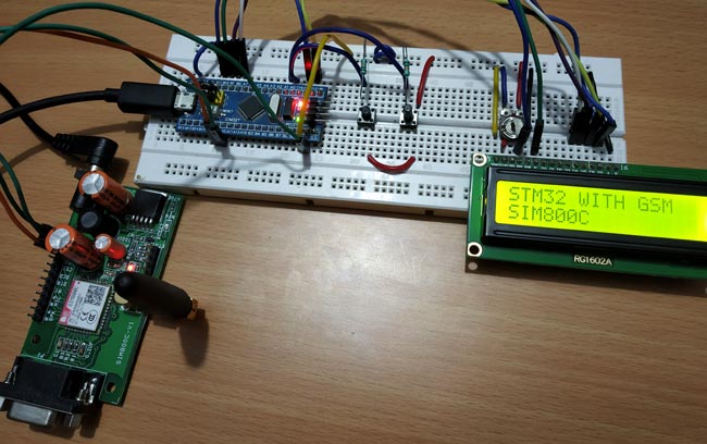
Two Push buttons with Pull down resistor of 10k is connected to the pins PA0 & PA1 of STM32 microcontroller. The complete setup will look lik below:
Programming STM32F103C8 Microcontroller for GSM interfacing
STM32F103C8 microcontroller can be programmed using ARDUINO IDE. In this tutorial, FTDI or ST-LINK programmer is not needed to program the STM32. For uploading code to STM32F103C8, simply plug microUSB port to STM32, and USB port to PC by using USB cable and start writing code in ARDUINO IDE. In case of any doubt follow our previous tutorials on how to program STM32 without using any external FTDI or ST-LINK Programmer.
The complete code and the working video can be found at the end of this tutorial.
Start with including necessary libraries for peripherals used in this tutorial. Also define the pin configuration of LCD.
#include <LiquidCrystal.h>
const int rs = PB11, en = PB10, d4 = PB0, d5 = PB1, d6 = PC13, d7 = PC14;
LiquidCrystal lcd(rs, en, d4, d5, d6, d7);
Next, initialise LCD selecting the function lcd.begin(16,2); where (16,2) tells the LCD type such as 16x2 block LCD display. Just print a message to debug that if LCD is giving Output and interfaced properly.
lcd.begin(16,2);
 lcd.print("STM32 WITH GSM");
 lcd.setCursor(0,1);
 lcd.print("SIM800C");
Define the Push button data direction as Input Mode and define the pin number used.
pinMode(PA0,INPUT);
pinMode(PA1,INPUT);
Select the baud rate used for serial communication.
Serial1.begin(9600);
There are two functions in the code one to send message and other one to receive message. Detailed explanation is given below.
SendMessage
This function is used to send SMS to a number. AT command is sent to GSM module indicating the message text mode and on which number the message needs to be sent.
The below statement sets the GSM module in the Text Mode by sending AT command (AT+CMGF=1).
Serial1.println("AT+CMGF=1"); //Sets the GSM Module in Text Mode
After that AT command (AT+CMGS) indicating send an SMS with the mobile number is sent to GSM module via serial1 port.
Serial1.println("AT+CMGS=\"+91XXXXXXXXXX\"\r"); // Replace x with mobile number
The messages are sent using AT command after every one second and then CLRL+Z needs to be sent so an ASCII code of CTRL+Z is sent via Serial1 port to GSM module.
delay(1000);
 Serial1.println("Hi Circuit Digest from GSM Module"); // The SMS text you want to send
 Serial1.println((char)26);// ASCII code of CTRL+Z
Then the “SMS sent” is displayed in the 16X2 LCD displayed.
lcd.print("SMS SENT");
ReceiveMessage
In this function, the messages are received and printed in the LCD display screen.
Serial1.println("AT+CNMI=2,2,0,0,0");
So, to receive live messages the above AT command is used.
After receiving the SMS, it contains a string available at the serial1 port which also have the other data in it such as the time, date etc. So, after occurrence of the sixth double quote (“) the rest all is the SMS received. Hence the other information is omitted and the remaining information that is the received message is displayed in the 16x2 LCD display.
while(1)
  {
           if(Serial1.available())
            {
                do
                  {
                     while ( !Serial1.available() );
                  } while ( '"' != Serial1.read() );
               do
                  {
                      while ( !Serial1.available() );
                  } while ( '"' != Serial1.read() );
               do
                 {
                      while ( !Serial1.available() );
                  } while ( '"' != Serial1.read() );
               do
                 {
                    while ( !Serial1.available() );
                 } while ( '"' != Serial1.read() );
                do
                  {
                     while ( !Serial1.available() );
                  } while ( '"' != Serial1.read() );
                do
                 {
                    while ( !Serial1.available() );
                  } while ( '"' != Serial1.read() );
                  while ( !Serial1.available() );
                  receive = Serial1.read();
                  while ( !Serial1.available() );
                  receive = Serial1.read();
    lcd.clear();
    while(1)
    {
        while ( !Serial1.available() );
        receive = Serial1.read();
        if ( receive == '\r' )
              break;
     else
             lcd.write(receive);
     }
}
}

Demo to Send and Receive Text Message using STM32
1. To send Text Message, simply press the Left Push button. The SMS will be sent to the mobile number entered in the code.
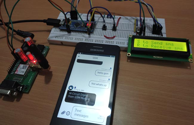
2. To receive Text Message, simply press the Right Push button and the SMS will be received and will be displayed in the LCD display screen.
So that’s all about interfacing GSM module with STM32F103C8 ARM microcontroller. In case of any doubts or suggestions, please feel free to comment.
Complete Project Code
#include <LiquidCrystal.h>                           //Library for LCD display
const int rs = PB11, en = PB10, d4 = PB0, d5 = PB1, d6 = PC13, d7 = PC14;      //Pins that are connected between LCD and STM32
LiquidCrystal lcd(rs, en, d4, d5, d6, d7);
int receive = 0;
void setup()
{
  lcd.begin(16,2);           //LCD set at 16x2 mode
  pinMode(PA0,INPUT);       //Push buttons as INPUT pins
  pinMode(PA1,INPUT);
  lcd.print("STM32 WITH GSM");   //Display Welcome message
  lcd.setCursor(0,1);
  lcd.print("SIM800C");
  Serial1.begin(9600);   // Setting the baud rate of GSM Module
  delay(1000);
  lcd.clear();
}
void loop()
{
  lcd.clear();
  lcd.setCursor(0,0);
  lcd.print("S to Send sms");
  lcd.setCursor(0,1);
  lcd.print("R to Receive sms");
  delay(100);
  int a = digitalRead(PA0);          //Read status of the push buttons
  int b = digitalRead(PA1);
  if (a == 1)                         // Depeding upon which push button is pressed the respected function is called
       {
         SendMessage();
       }
else if( b == 1)
      {
         RecieveMessage();
      }
}
 void SendMessage()      //Function to Send Message
{
  lcd.clear();
  lcd.print("Sending sms");
  delay(1000);
  Serial1.println("AT+CMGF=1");    //Sets the GSM Module in Text Mode
  delay(1000);
  Serial1.println("AT+CMGS=\"+91XXXXXXXXXX\"\r"); // Replace x with mobile number
  delay(1000);
  Serial1.println("Hi Circuit Digest from GSM Module"); // The SMS text you want to send
  delay(100);
  Serial1.println((char)26);// ASCII code of CTRL+Z
  delay(1000);
  lcd.clear();
  lcd.print("SMS SENT");
  delay(1000);
}
 void RecieveMessage()         //Function to Receive Message
{
  lcd.clear();
  lcd.print("Receiving sms");
  Serial1.println("AT+CNMI=2,2,0,0,0"); // AT Command to recieve a live SMS
  delay(1000);
  while(1)
  {
           if(Serial1.available())
            {
                do
                  {
                     while ( !Serial1.available() );
                  } while ( '"' != Serial1.read() );
               do
                  {
                      while ( !Serial1.available() );
                  } while ( '"' != Serial1.read() );
               do
                 {
                      while ( !Serial1.available() );
                  } while ( '"' != Serial1.read() );
               do
                 {
                    while ( !Serial1.available() );
                 } while ( '"' != Serial1.read() );
                do
                  {
                     while ( !Serial1.available() );
                  } while ( '"' != Serial1.read() );
                do
                 {
                    while ( !Serial1.available() );
                  } while ( '"' != Serial1.read() );
                  while ( !Serial1.available() );
                  receive = Serial1.read();
                  while ( !Serial1.available() );
                  receive = Serial1.read();
    lcd.clear();
    while(1)
    {
        while ( !Serial1.available() );
        receive = Serial1.read();
        if ( receive == '\r' )
              break;
        else
             lcd.write(receive);
     }
}
}
}
Comments
Hii please sand Arduino Uno
Hii please sand Arduino Uno cod
GSM SIM800C Modem

Hello Dear
Send code is working but Receving code does not work.Please suggest
Regards
Manoj Goyal