

Light fence circuit is used to detect the presence of any human or object in a particular area. The detecting range of Light Fence Circuit is about 1.5 to 3 meters. It’s quite simple to design the circuit using LDR and Op-amp. This portable circuit can work smoothly with a commonly available 9V battery and the alarm sound generated from the buzzer is loud enough to detect the presence of a human, vehicle or object.
This kind of security system can also built by using other sensors instead of using LDR, like:
- PIR based Burglar Alarm Circuit
- IR Based Security Alarm
- Laser Security Alarm Circuit
- Magnetic Door Alarm Circuit using Hall Sensor
Components Required
- LM741 Op-amp IC
- 555 timer IC
- BC557 – PNP Transistor
- LDR
- Resistor (210, 1K, 5.7K, 100k, 1M)
- Capacitor (0.1uf, 10uf)
- Potentiometer – 100K
- Buzzer
- LED
- Battery - 9V
- Breadboard
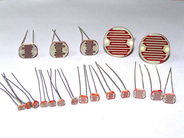
LDR
LDR is Light Dependent Resistor. LDRs are made from semiconductor materials to enable them to have their light-sensitive properties. There are many types but one material is popular and it is cadmium sulfide (CdS). These LDRs or PHOTO RESISTORS works on the principle of “Photo Conductivity”. Now what this principle says is, whenever light falls on the surface of the LDR (in this case) the conductance of the element increases or in other words, the resistance of the LDR falls when the light falls on the surface of the LDR. This property of the decrease in resistance for the LDR is achieved because it is a property of semiconductor material used on the surface.
We have previously built made many Circuits using LDR, which use LDR to automate the lights according to requirement.
555 Timer IC
555 Timer IC is one of the most used IC in electronics, especially for triggering purpose. To learn more about it follow our various 555 Timer circuits. Here we are using 555 Timer IC in astable mode to create a beeping sound with Buzzer. Below we have explained the behavior of each of the pin of 555 Timer IC when operating in Astable mode.
Pin 1. Ground: This pin should be connected to ground.
Pin 2. TRIGGER: Trigger pin is dragged from the negative input of comparator two. The Lower comparator output is connected to SET pin of flip-flop. A negative pulse (< Vcc/3) on this Pin sets the Flip flop and output goes High.
Pin 3. OUTPUT: This pin also has no special function. This is output pin where Load is connected. It can be used as source or sink and drive upto 200mA current.
Pin 4. Reset: There is a flip-flop in the timer chip. Reset pin is directly connected to MR (Master Reset) of the flip-flop. This is a active Low pin and normally connected to VCC for preventing accidental Reset.
Pin 5. Control Pin: The control pin is connected from the negative input pin of comparator one. Output Pulse width can be controlled by applying voltage at this Pin, irrespective of RC network. Normally this pin is pulled down with a capacitor (0.01uF), to avoid unwanted noise interference with the working.
Pin 6. THRESHOLD: Threshold pin voltage determines when to reset the flip-flop in the timer. The threshold pin is drawn from positive input of upper comparator. If the control pin is open, then a voltage equal to or greater than VCC*(2/3) will reset the flip-flop. So the output goes low.
Pin 7. DISCHARGE: This pin is drawn from the open collector of transistor. Since the transistor (on which discharge pin got taken, Q1) got its base connected to Qbar. Whenever the output goes low or the flip-flop gets reset, the discharge pin is pulled to ground and capacitor discharges.
Pin 8. Power or VCC: It is connected to positive voltage (+3.6v to +15v).
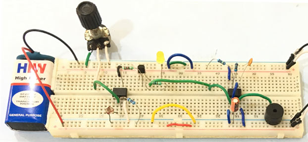
Circuit Diagram

Complete circuit diagram for Automatic Fence Lighting with Alarm is shown above. LDR is placed facing towards the entrance and a potentiometer is used to adjust the sensitivity of the device. You can also add a switch between the negative pin of the battery and LDR’s grounded pin to control this security system manually.
Working of Light Fence Circuit
Here, the op-amp IC is used as a voltage comparator and the 555 timer IC is placed in an astable mode. The LDR and the potentiometer are creating a voltage divider circuit. The output of this divider circuit will change according to the intensity of light falls on the LDR. The divider is connected to the inverting pin of the Op-amp IC. The non-inverting pin is connected with supply through a 5.7Kohm resistor, so the voltage value at the non-inverting is fix. You can replace this resistor with a 10K potentiometer to adjust the voltage as per the requirement.
We can adjust the sensitivity of the device by using the potentiometer VR1 connected in series with the LDR. When the voltage at non-inverting input is greater than or equal to the reference voltage the output (at pin 6) of the op-amp IC output (PIN 6) goes HIGH. Learn more about working of op-amp by following the various op-amp based circuits.
According to the circuit diagram, when LDR detects any activity the output of the Op-amp IC goes LOW, and PNP transistor T1 start conducting. Hence, the LED starts glowing and the 555 timer IC get triggered. Here, 555 timer IC is in Astable mode and a preset time delay is provided by R3, R5 and C1.
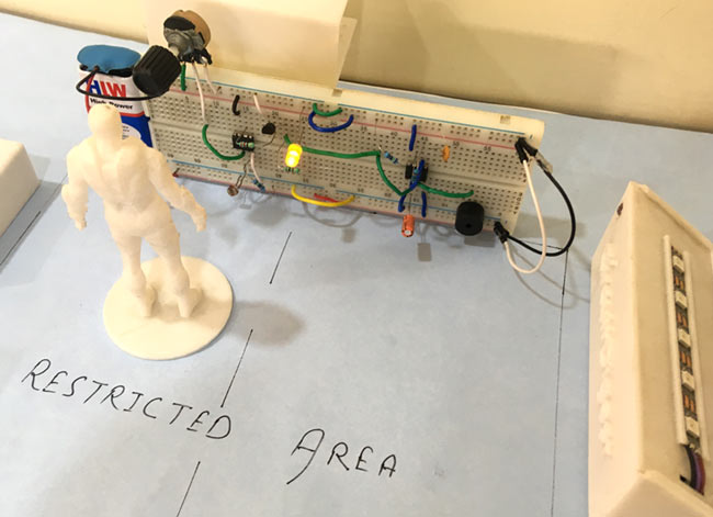
So whenever some person or object enters in prohibited area, his shadows will be sensed by the LDR and the circuit triggers the alarm.

pnp transistor other than 557