
A burglar alarm system is an important part of home security systems. This burglar alarm project is based on a PIR sensor, UM3561 and a Speaker. PIR sensor used to detect body motion and UM3561 & speaker to produce a Police siren after any movement detection. Our simple burglar alarm circuit diagram provides an affordable DIY solution for enhancing your home security.
Table of Contents
What is a Burglar Alarm System?
A burglar alarm system is an electronic security device that detects any unauthorised movement into an area or building. Again, burglar alarm system working principles are based on motion sensor triggering audio alerts on detection of movement. This home burglar security alarm system project uses infrared technology to check for human presence and activate a police siren sound.
Required Components for Burglar Alarm Project
To build this burglar alarm system project, you'll need the following electronic components:
- PIR sensor
- UM3561 IC
- Resistors 220K and 10K
- Transistor BC547
- Speaker 8ohm
- 9V Battery and Battery Snap Connector
- Breadboard Wires
- Breadboard
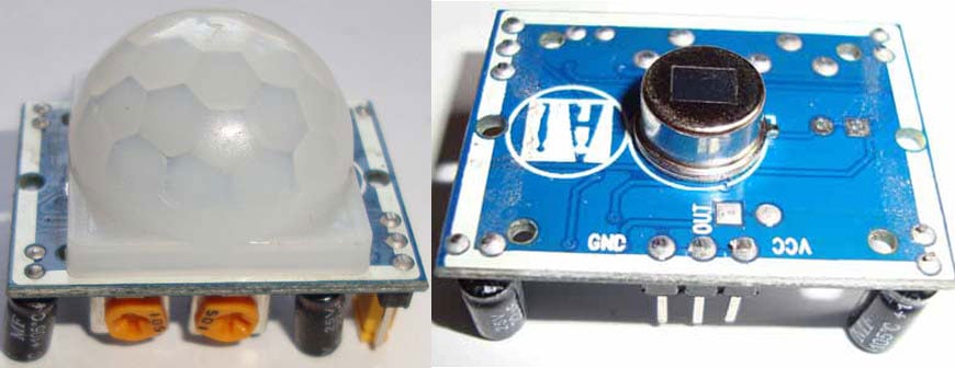
PIR Sensor for Motion Detection
The PIR (Passive Infrared) sensor is the heart of our burglar alarm system using pir sensor. Whenever there is any body movement, the voltage at the output pin changes. Basically, it detects the Change in Heat and produces output whenever such a detection occurs. You can learn more about the PIR sensor in this PIR sensor circuit. There are some useful features in the PIR sensor, like how to change the distance range, how to set the Alarm duration, etc.
Important Attributes of a PIR Sensor:
∗ Detection Distance: maximum up to 7 meters (user adjustable)
∗ Detection Angle: 120 degrees
∗ Output Voltage: 3.3V when there is motion
∗ Sensitivity Adjust Control: adjustable potentiometer
∗ Delay Time: adjustable time delay (from 0.3s to 5 minutes)
UM3561 IC
UM3561 is a CMOS LSI IC which can generate four types of sound: Police Siren, Ambulance siren, Fire brigade siren and machine gun sound. It is generally used in alarms and toys. It is an 8-pin IC and only requires an external resistor to work. It has inbuilt oscillators and circuitry to produce the sounds. UM3561 works in the range of 3-5 volts; voltages higher than 5V can damage the IC, so if we are using it with another circuit or using a high voltage source, a Zener diode must be connected to protect the IC. The output generated by the IC is not sufficient to drive an 8-ohm small speaker, so to amplify the output of the IC, a transistor must be used at the output (PIN 3).
Pin diagram and Pin description are given below, taken from its Datasheet:
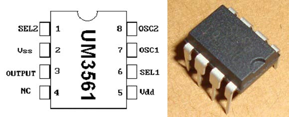
| Pin No. | Symbol | Description |
| 1 | SEL2 | Sound Effect Selection Pin No.2 |
| 2 | Vss | Ground |
| 3 | Output | OUTPUT |
| 4 | NC | Internal Testing Pin: Leave Open for Normal Operations |
| 5 | Vdd | Positive Power Supply |
| 6 | SEL1 | Sound Effect Selection Pin No.1 |
| 7 | OSC1 | External Oscillator Terminal 1 |
| 8 | OSC2 | External Oscillator Terminal 2 |
We can play four sounds by using its 2 sound Effect selection Pins (SEL 1 and SEL 2), like here in our circuit, we kept SEL 1 and SEL 2 open, to produce the Police Siren sound. Below is the table for 4 Playing modes. You can produce whatever sound you want.
| SEL 1 | SEL 2 | Sound Effect |
| NC | NC | Police Siren |
| Vdd | NC | Fire Brigade Siren |
| Vss | NC | Ambulance Siren |
| X | Vdd | Machine Gun |
NC: No Connection
X: Don’t Care
Zener Diode
Zener Diodes are just like the other diodes, with only one difference. All the diodes allow the flow of current in only one direction (forward), but the Zener diode can allow current in the reverse direction if the voltage goes beyond a certain limit. This voltage is called Breakdown Voltage or Zener Knee voltage. So this property of the Zener diode protects the UM3561 IC by preventing a higher voltage supply to it.
Burglar Alarm Circuit Diagram and Working
Our simple burglar alarm circuit diagram shows the full burglar alarm system using PIR sensor wiring diagram. The circuit works on a simple principle: the PIR sensor picks up the movement, and it operates the sound generator circuit.

Circuit Working Principle
This burglar alarm circuit is very simple. Whenever the PIR sensor detects any human body movement, its OUTPUT pin becomes HIGH, which is connected to UM3561’s Power supply PIN 5. So UM3561 is activated and starts producing sound with the Speaker. As I have stated above that UM3561 doesn’t produce much output to drive a Speaker, so we need to connect a Transistor to amplify the current. As long as the PIR sensor OUTPUT pin is HIGH, the alarm (Speaker) will be continuously ringing, with the sound produced by UM3561. We can set the time duration of the Alarm by setting the PIR sensor’s Time delay control regulator; you can set it as long as you want.
Here we should note that we didn’t use a Zener diode because here in our circuit we are connecting UM3561 with the PIR sensor’s output, and the PIR sensor gives an output of approximately. 3.3v, which is in the range of the operating voltage of UM3561, so we do not need any protection from high voltage. Though you can use it for precautionary purposes.
Troubleshooting Common Issues
| Problem | Possible Cause | Solution |
|---|---|---|
| No sound output | Loose connections | Check all wiring connections |
| Continuous alarm | PIR sensitivity is too high | Adjust the PIR sensitivity potentiometer |
| Weak sound output | Low battery voltage | Replace 9V battery |
| No motion detection | PIR sensor malfunction | Check the PIR power supply and connections |
Advanced Modifications and Improvements
- SMS Alerts: An additional GSM module could be used to send alerts to mobile phones.
- Remote Control: Some RF modules can be exploited for turn-on/turn-off remote control.
- Multiple Sensors: Multiple motion sensors/PIR Sensors can be incorporated, so more sensors can be connected.
- LED Indicators: Add LEDs to indicate system status.
- Battery Backup: add a rechargeable battery pack for backup.
- Sound Selection: Add switches for selecting an alternate siren.
Safety Considerations-Best Practices
» Always disconnect power before working on any modification involving circuits.
» Make sure only appropriate voltages are applied; components might get damaged.
» Install the system away from sunlight and moisture.
» Make sure to test the system regularly in case something breaks or malfunctions.
» Have spare batteries to prevent downtime.
This burglar alarm project is a simple introduction to electronic security systems. By integrating a PIR Sensor and sound generation with the UM3561, we have created a very simple burglar alarm circuit to demonstrate and use for home security projects and an educational project within schools. When created and tested correctly, this simple burglar alarm circuit diagram will provide motion detection and audio alerts for protecting your property.
If you want to connect a bigger alarm to the PIR sensor, which works on AC mains 220V, then you need to connect it with a Relay. Here is the CIRCUIT, you just need to replace the bulb with an AC alarm. There are a lot of alarms available in the market.
Frequently Asked Questions on Burglar Alarm System Project
⇥ How is a PIR sensor used in a burglar alarm system?
PIR sensors sense infrared radiation variations of warm moving objects. When a human moves into the detection area, the sensor activates upon sensing temperature variations, sending a 3.3V signal to activate the components of the alarm circuit.
⇥ What is the detection range of this burglar alarm circuit?
The HC-SR501 PIR sensor generally senses motion at 7 meters and a 120-degree angle. The range and sensitivity can be adjusted with the onboard potentiometers on the sensor board to provide a tailored coverage area.
⇥ Why does this burglar alarm project require a transistor?
There is a variety of circuits available online in which the UM3561 IC produces a very weak output current with a single 8Ω speaker. The BC547 transistor allows for amplification of the signal current sufficiently to ensure enough power is delivered for a clear and audible sound output of the alarm.
⇥ Can I use this burglar alarm system with AC mains power?
This circuit operates from DC provided by a 9V battery. In any case, the manual warns that one should use transformers, rectifiers, and voltage regulators to provide a safe and stable DC power supply, or else AC mains may be used directly.
⇥ How to modify the siren sound in UM3561 IC?
UM3561 provides four sound modes governed by SEL1 and SEL2 pins. Connect SEL1 to VDD for the fire alarm, to GND for the ambulance, or SEL2 to VDD for the machine gun sound.
⇥ What triggers false alarms in PIR-based security systems?
Pets, swinging curtains, temperature variation, sunlight, and electrical interference are common causes. All of these can be kept to a minimum by adjusting PIR sensitivity, mounting away from heat sources, and proper mounting positions.
Projects Related to Alarm Systems and Their Applications
We’ve transformed this alarm project into the foundation for many innovative applications—discover them through the links below.

Dog Barking Security Alarm using Arduino
So in this tutorial, we are going to build a Dog Barking Security Alarm using Arduino Nano, PIR Motion Sensor, and Dog Barking Sound Module. When someone gets close to your house door, a barking dog alarm will be triggered from inside the house, making all undesirable guests go away.

Magnetic Door Alarm Circuit using Hall Sensor
A door alarm is a very common and useful device for security purposes. They are used to detect whether the Door is open or closed. Door Alarm Projects are very popular among Electronics students and hobbyists.

Simple Water Level Indicator Alarm with Buzzer
This comprehensive water level indicator project tutorial will guide you to build a simple DIY water level indicator circuit that detects water levels and raises an alarm when your tank reaches preset levels - perfect for preventing overflow and water wastage.
Comments
thnxx for posting this project..
all the best
Thank you so much for posting these electronics circuits .they really helped us a lot.
I would like to see if this works
I am crazy for circuit designing and it is Very good Explaination,I like it .(Shukriya Dost).If more suggestion you can give me.I am always here.
Hey, I'm trying to replicate this project, but I can't find the UM3561 IC anywhere, do you have a suggestion for a substitute?
please give me this project simulation.
I will like you to help me out with the project materials on the construction of a wireless car security system.
I love your project work
Hello my name is Majid thank you for making this circuit however i cant seem to make the simulation for it.Can someone send it to me? much appreciated
pls send me the steps in making it, will be very great full, i want to use for my project
Thank you so much for this illustration but please this is a project I am to carryout but it will incorporate fingerprint as its sensing unit. Please I need the circuit diagram and the operation principle, that is, the methodology on how the circuit will work.
Please I am waiting for your reply as quick as possible.
can i get the full module of this project
please help me with report document for burglar alarm circuit project.

Thank you so much for posting this project! I made it for my final project in my basic electrical engineering class, and it turned out great.
Thank you.