

PWM signal generation is a vital tool in every embedded engineers arsenal, they come in very handy for lot of applications like controlling the position of servo motor, switching few power electronic ICs in converters/invertors and even for a simple LED brightness control. In PIC microcontrollers PWM signals can be generated using the Compare, Capture and PWM (CCP) modules by setting the required Registers, we have already learnt how to do that in the PIC PWM tutorial. But there is one considerable drawback with that method.
The PIC16F877A can generate PWM signals only on pins RC1 and RC2, if we use the CCP modules. But we might encounter situations, where we need more pins to have PWM functionality. For instance in my case, I want to control 6 RC servo motors for my robotic arm project for which the CCP module is hopeless. In these scenarios we can program the GPIO pins to produce PWM signals using timer modules. This way we can generate as many PWM signals with any required pin. There are also other hardware hacks like using a multiplexer IC, but why invest on hardware when the same can be achieved though programming. So in this tutorial we will learn how to convert a PIC GPIO pin into a PWM pin and to test it we will simulate it on proteus with digital oscilloscope and also control the position of Servo motor using the PWM signal and vary its duty cycle by varying a potentiometer.
What is a PWM Signal?
Before we get into the details, let us brush up a bit on what PWM Signals are. Pulse Width Modulation (PWM) is a digital signal which is most commonly used in control circuitry. This signal is set high (5v) and low (0v) in a predefined time and speed. The time during which the signal stays high is called the “on time” and the time during which the signal stays low is called the “off time”. There are two important parameters for a PWM as discussed below:
Duty cycle of the PWM
The percentage of time in which the PWM signal remains HIGH (on time) is called as duty cycle. If the signal is always ON it is in 100% duty cycle and if it is always off it is 0% duty cycle.
Duty Cycle =Turn ON time/ (Turn ON time + Turn OFF time)
Frequency of a PWM
The frequency of a PWM signal determines how fast a PWM completes one period. One Period is complete ON and OFF of a PWM signal as shown in the above figure. In our tutorial we will set a frequency of 5KHz.
Calculating Duty Cycle for PWM
To generate PWM signal on a GPIO pin we have to simply turn it on and off for a pre-defined time. But it is not as simple as it sounds. This on time and off time should be accurate for every cycle so we simply cannot use delay functions, hence we employ a timer module and use the timer interrupts. Also we have to consider the duty cycle and the frequency of the PWM signal that we generate. The following variable names are used in program to define the parameters.
|
Variable Name |
Refers to |
|
PWM_Frequency |
Frequency of the PWM Signal |
|
T_TOTAL |
Total time taken for one complete cycle of PWM |
|
T_ON |
On time of the PWM signal |
|
T_OFF |
Off time of the PWM signal |
|
Duty_cycle |
Duty cycle of the PWM signal |
So now, let’s do the math.
This is the standard formulae where frequency is simply the reciprocal of time. The value of frequency has to be decided and set by the user based on his/her application requirement.
T_TOTAL = (1/PWM_Frequency)
When the user changes the Duty cycle value, our program should automatically adjust the T_ON time and T_OFF time according to that. So the above formulae can be used to calculate T_ON based on the value of Duty_Cycle and T_TOTAL.
T_ON = (Duty_Cycle*T_TOTAL)/100
Since the Total time of the PWM signal for one full cycle will be the sum of on time and off time. We can calculate the off time T_OFF as shown above.
T_OFF = T_TOTAL – T_ON
With these formulae in mind we can begin programming the PIC microcontroller. The program involves the PIC Timer Module and PIC ADC Module to create a PWM signal based with a varying Duty cycle according to the ADC value form the POT. If you are new to using these modules then it is strongly recommended to read the appropriate tutorial by clicking on the hyperlinks.
Programming PIC to generate PWM on GPIO Pins
The complete program for this tutorial can be found at the bottom of the website like always. In this section let’s understand how the program is actually written. Like all programs, we begin by setting the configurations bits. I have used the memory views option to set it for me.
// CONFIG
#pragma config FOSC = HS        // Oscillator Selection bits (HS oscillator)
#pragma config WDTE = OFF       // Watchdog Timer Enable bit (WDT disabled)
#pragma config PWRTE = OFF      // Power-up Timer Enable bit (PWRT disabled)
#pragma config BOREN = ON       // Brown-out Reset Enable bit (BOR enabled)
#pragma config LVP = OFF        // Low-Voltage (Single-Supply) In-Circuit Serial Programming Enable bit (RB3 is digital I/O, HV on MCLR must be used for programming)
#pragma config CPD = OFF        // Data EEPROM Memory Code Protection bit (Data EEPROM code protection off)
#pragma config WRT = OFF        // Flash Program Memory Write Enable bits (Write protection off; all program memory may be written to by EECON control)
#pragma config CP = OFF         // Flash Program Memory Code Protection bit (Code protection off)

// #pragma config statements should precede project file includes.
// Use project enums instead of #define for ON and OFF.

#include <xc.h>
Then we mention the clock frequency used in the hardware, here my hardware uses 20MHz crystal, you can enter the value based in your hardware. Followed by that is the frequency value of the PWM signal. Since my aim here it to control a hobby RC servo motor which requires a PWM frequency of 50Hz I have set 0.05KHz as the Frequency value you can also change this based in your application requirements.
#define _XTAL_FREQ 20000000
#define PWM_Frequency 0.05 // in KHz (50Hz)
Now, that we have the value of Frequency we can calculate the T_TOTAL using the above discussed formulas. The result is dived by 10 to get the value of time in milli seconds. In my case the value of T_TOTAL will be 2 milli seconds.
int T_TOTAL = (1/PWM_Frequency)/10; //calculate Total Time from frequency (in milli sec)) //2msec
Followed by that, we initialize the ADC modules for reading the position of the Potentiometer as discussed in our ADC PIC tutorial. Next we have the Interrupt service routine which will be called every time, the timer overflows we will get back to this later, for now let’s check the main function.
Inside the main function we configure the timer module. Here I have configured the Timer module to overflow for every 0.1ms. The value for the time can be calculated by using the formulae below
RegValue = 256-((Delay * Fosc)/(Prescalar*4)) delay in sec and Fosc in hz
In my case for a delay of 0.0001 seconds (0.1ms) with prescalar of 64 and Fosc of 20MHz the value of my register (TMR0) should be 248. So the configuration looks like this
/*****Port Configuration for Timer ******/
    OPTION_REG = 0b00000101;  // Timer0 with external freq and 64 as prescalar // Also Enables PULL UPs
    TMR0=248;       // Load the time value for 0.0001s; delayValue can be between 0-256 only
    TMR0IE=1;       //Enable timer interrupt bit in PIE1 register
    GIE=1;          //Enable Global Interrupt
    PEIE=1;         //Enable the Peripheral Interrupt
    /***********______***********/
Then we have to set the Input and Output configuration. Here we are using the AN0 pin for reading the ADC value and PORTD pins to output the PWM signals. So initiate them as output pins and make them low by using the below lines of code.
    /*****Port Configuration for I/O ******/
    TRISD = 0x00; //Instruct the MCU that all pins on PORT D are output
    PORTD=0x00; //Initialize all pins to 0
    /***********______***********/
Inside the infinite while loop, we have to calculate the value of on time (T_ON) from the duty cycle. The on time and duty cycle varies based on the position of the POT so we do it repeatedly inside the while loop as shown below. 0.0976 is the value that has to be multiplied with 1024 to get 100 and to calculate T_ON we have multiplied it with 10 to get value in milli seconds.
while(1)
    {
       POT_val = (ADC_Read(0)); //Read the value of POT using ADC

       Duty_cycle = (POT_val * 0.0976); //Map 0 to 1024 to 0 to 100

       T_ON = ((Duty_cycle * T_TOTAL)*10 / 100); //Calculate On Time using formulae unit in milli seconds

       __delay_ms(100);
    }
Since the timer is set to over flow for every 0.1ms, the timer interrupt service routine ISR will be called for every 0.1ms. Inside the service routine we use a variable called count and increment it for every 0.1ms. This way we can keep track f time. To learn more about Interrupts in PIC microcontroller, follow the links
    if(TMR0IF==1) // Timer flag has been triggered due to timer overflow -> set to overflow for every 0.1ms
    {
        TMR0 = 248;     //Load the timer Value
        TMR0IF=0;       // Clear timer interrupt flag
        count++; //Count increments for every 0.1ms -> count/10 will give value of count in ms
    }
Finally it is time to toggle the GPIO pin based on the value of T_ON and T_OFF. We have the count variable that keeps track of time in milli seconds. So we use that variable to check if time is less than on time, if yes then we keep the GPIO pin turned on else we turn it off and keep it turned off until the new cycle starts. This can be done by comparing it to the total time of one PWM cycle. The code to do the same is shown below
if (count <= (T_ON) ) //If time less than on time
        RD1=1; //Turn on GPIO
    else
        RD1=0; //Else turn off GPIO

    if (count >= (T_TOTAL*10) ) //Keep it turned off until a new cycle starts
        count=0;
Circuit Diagram
The circuit diagram for generating PWM with GPIO pin of PIC microcontroller is really simple, just power the PIC with oscillator and connect the potentiometer to pin AN0 and Servo Motor to pin RD1, we can use GPIO pin to get the PWM signal, I have selected RD1 just out of random. Both the Potentiometer and the Servo motor is powered by 5V which is regulated from the 7805 as shown below in the circuit diagram.

Simulation
To simulate the project I used my proteus software. Build the circuit shown below and link the code to your simulation and run it. You should get a PWM signal on the RD1 GPIO pin as per our program and the duty cycle of the PWM should get controlled based on the position of the potentiometer. The below GIF shows how the PWM signal and servo motor respond when the ADC value is changed through the potentiometer.

Hardware Setup for controlling Servo Motor using PIC Microcontroller
My complete hardware set-up is shown below, for people who are following my tutorials this board should look familiar, it is the same board which I have used in all my tutorials so far. You can refer the Blinking LED tutorial if you are interested in knowing how I build it. Otherwise just follow the circuit diagram above and all should work fine.
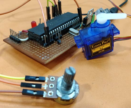
Upload the program and vary the potentiometer and you should see the servo changing the position based on the position of the potentiometer. The complete working of the project is shown in the video given at the end of this page. Hope you understood the project and enjoyed building, if you have quires, feel free to post them on the forum and I will try my best in answering.
I am planning to take this project forward by adding options to control multiple servo motors and thus building a robotic arm out of it, similar to the Arduino Robotic Arm that we already built. So until then see ya!!
Complete Project Code
/*

 * File:   PIC_GPIO_PWM.c

 * Author: Aswinth

 *

 * Created on 17 October, 2018, 11:59 AM

 */

// CONFIG

#pragma config FOSC = HS        // Oscillator Selection bits (HS oscillator)

#pragma config WDTE = OFF       // Watchdog Timer Enable bit (WDT disabled)

#pragma config PWRTE = OFF      // Power-up Timer Enable bit (PWRT disabled)

#pragma config BOREN = ON       // Brown-out Reset Enable bit (BOR enabled)

#pragma config LVP = OFF        // Low-Voltage (Single-Supply) In-Circuit Serial Programming Enable bit (RB3 is digital I/O, HV on MCLR must be used for programming)

#pragma config CPD = OFF        // Data EEPROM Memory Code Protection bit (Data EEPROM code protection off)

#pragma config WRT = OFF        // Flash Program Memory Write Enable bits (Write protection off; all program memory may be written to by EECON control)

#pragma config CP = OFF         // Flash Program Memory Code Protection bit (Code protection off)
// #pragma config statements should precede project file includes.

// Use project enums instead of #define for ON and OFF.
#include <xc.h>

#define _XTAL_FREQ 20000000

#define PWM_Frequency 0.05 // in KHz (50Hz)

//TIMER0    8-bit  with 64-bit Prescalar

//$$RegValue = 256-((Delay * Fosc)/(Prescalar*4))  delay in sec and Fosc in hz  ->Substitute value of Delay for calculating RegValue
int POT_val; //variable to store value from ADC

int count; //timer variable

int T_TOTAL = (1/PWM_Frequency)/10; //calculate Total Time from frequency (in milli sec)) //2msec

int T_ON=0; //value of on time

int Duty_cycle; //Duty cycle value
void ADC_Initialize() //Prepare the ADC module

{

  ADCON0 = 0b01000001; //ADC ON and Fosc/16 is selected

  ADCON1 = 0b11000000; // Internal reference voltage is selected

}
unsigned int ADC_Read(unsigned char channel) //Read from ADC

{

  ADCON0 &= 0x11000101; //Clearing the Channel Selection Bits

  ADCON0 |= channel<<3; //Setting the required Bits

  __delay_ms(2); //Acquisition time to charge hold capacitor

  GO_nDONE = 1; //Initializes A/D Conversion

  while(GO_nDONE); //Wait for A/D Conversion to complete

  return ((ADRESH<<8)+ADRESL); //Returns Result

}
void interrupt timer_isr()

{

    if(TMR0IF==1) // Timer flag has been triggered due to timer overflow -> set to overflow for every 0.1ms

    {

        TMR0 = 248;     //Load the timer Value

        TMR0IF=0;       // Clear timer interrupt flag

        count++; //Count increments for every 0.1ms -> count/10 will give value of count in ms

    }


    if (count <= (T_ON) )

        RD1=1;

    else

        RD1=0;


    if (count >= (T_TOTAL*10) )

        count=0;

}
void main()

{

/*****Port Configuration for Timer ******/

    OPTION_REG = 0b00000101;  // Timer0 with external freq and 64 as prescalar // Also Enables PULL UPs

    TMR0=248;       // Load the time value for 0.0001s; delayValue can be between 0-256 only

    TMR0IE=1;       //Enable timer interrupt bit in PIE1 register

    GIE=1;          //Enable Global Interrupt

    PEIE=1;         //Enable the Peripheral Interrupt

    /***********______***********/


    /*****Port Configuration for I/O ******/

    TRISD = 0x00; //Instruct the MCU that all pins on PORT D are output

    PORTD=0x00; //Initialize all pins to 0

    /***********______***********/


    ADC_Initialize();
    while(1)

    {

       POT_val = (ADC_Read(0)); //Read the value of POT using ADC


       Duty_cycle = (POT_val * 0.0976); //Map 0 to 1024 to 0 to 100


       T_ON = ((Duty_cycle * T_TOTAL)*10 / 100); //Calculate On Time using formulae unit in milli seconds
       __delay_ms(100);


    }


}
Comments
Hello Mr. Aswinth Raj,
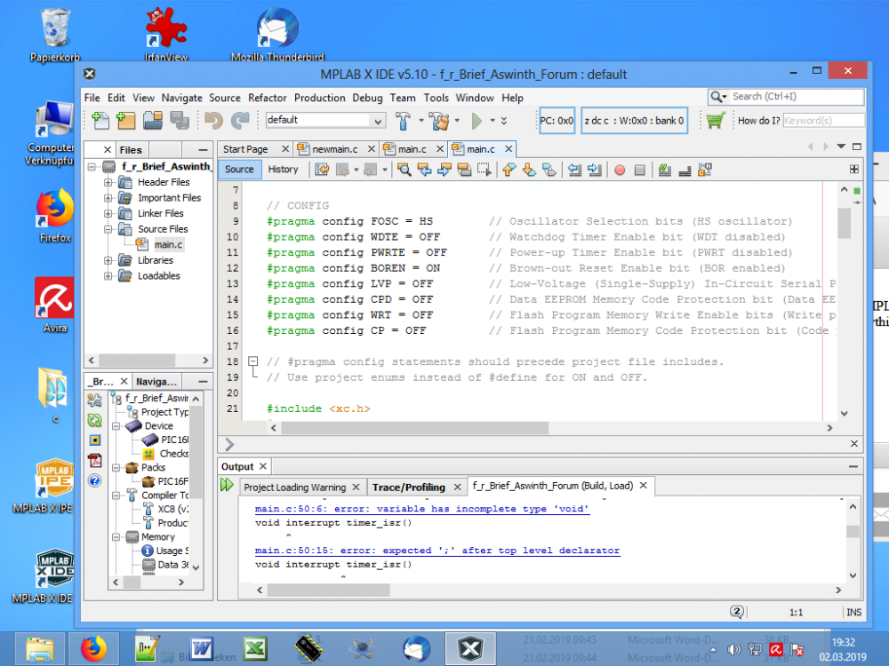
As a total beginner I tried to compile the source code to your above mentioned PIC project, in MPLAB X vers.5.10 and the compiler Free XC 8 vers 2.00, which I did not succeed. I did not change anything about the code. I have attached a screenshot of the errors here. What am I doing wrong.
Yours sincerely
Herbert Wichmann
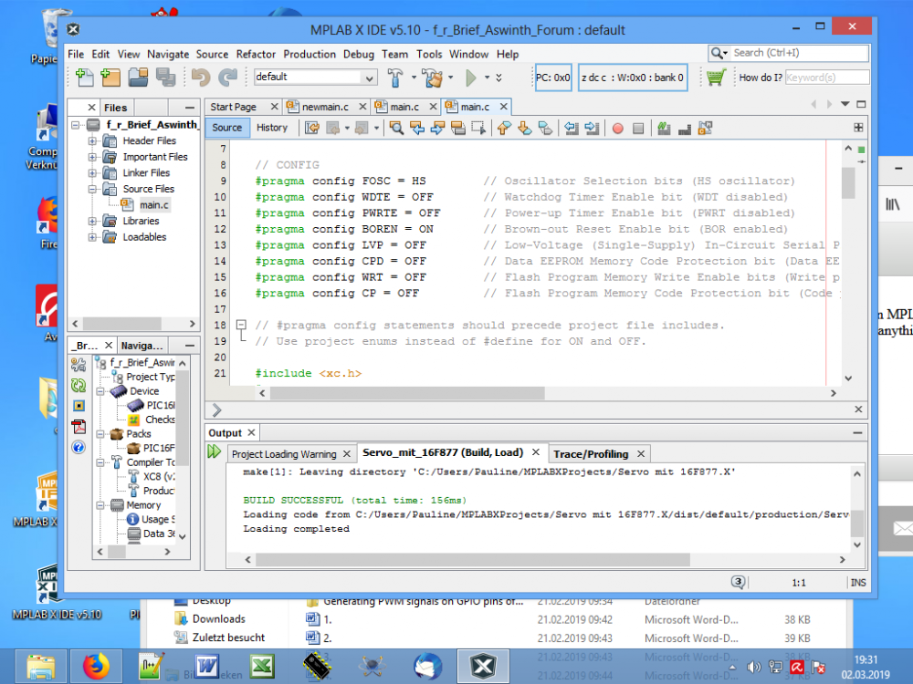
Hello Mr. Aswinth Raj, to my post from the 4th of March 2019 here is the text that the compiler issues. Would be glad if someone could help me.
Greeting Herbert Wichmann
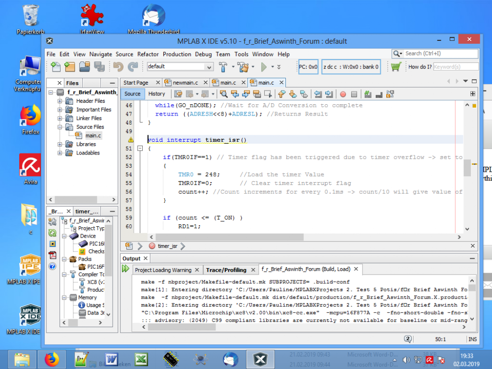
Compiler Ausgabe
make -f nbproject/Makefile-default.mk SUBPROJECTS= .build-conf
make[1]: Entering directory 'C:/Users/Pauline/MPLABXProjects/PWM Servo Aswinth mit 16F877A
make -f nbproject/Makefile-default.mk dist/default/production/PWM_Servo_Aswinth_mit_16F877A__
make[2]: Entering directory 'C:/Users/Pauline/MPLABXProjects/PWM Servo Aswinth mit 16F877A das im Brief.X'
"C:\Program Files\Microchip\xc8\v2.00\bin\xc8-cc.exe" -mcpu=16F877A -c -fno-short-double -fno-short-float -O0 -fasmfile -maddrqual=ignore -xassembler-with-cpp -Wa,-a -DXPRJ_default=default -msummary=-psect,-class,+mem,-hex,-file -ginhx032 -Wl,--data-init -mno-keep-startup -mno-osccal -mno-resetbits -mno-save-resetbits -mno-download -mno-stackcall -std=c99 -gdwarf-3 -mstack=compiled:auto:auto -o build/default/production/main.p1 main.c
::: advisory: (2049) C99 compliant libraries are currently not available for baseline or mid-range devices, or for enhanced mid-range devices using a reentrant stack; using C90 libraries
main.c:50:6: error: variable has incomplete type 'void'
make[2]: *** [build/default/production/main.p1] Error 1
void interrupt timer_isr()
make[1]: *** [.build-conf] Error 2
make: *** [.build-impl] Error 2
^
main.c:50:15: error: expected ';' after top level declarator
void interrupt timer_isr()
^
;
2 errors generated.
(908) exit status = 1
nbproject/Makefile-default.mk:106: recipe for target 'build/default/production/main.p1' failed
make[2]: Leaving directory 'C:/Users/Pauline/MPLABXProjects/PWM Servo Aswinth mit 16F877A das im Brief.X'
nbproject/Makefile-default.mk:90: recipe for target '.build-conf' failed
make[1]: Leaving directory 'C:/Users/Pauline/MPLABXProjects/PWM Servo Aswinth mit 16F877A das im Brief.X'
nbproject/Makefile-impl.mk:39: recipe for target '.build-impl' failed
BUILD FAILED (exit value 2, total time: 1s)
Hello Mr. Aswinh,
Thank you for your feedback and help.
No, I have not changed the code, I lack the experience. I have marked the main.c code on your page and copied it into Nodpat + and then put the code in MPLAB X. I have attached the code here as I inserted it in MPLAB X.
I would be glad to receive further help from you.
Yours sincerely
Herbert Wichmann
/*
* File: PIC_GPIO_PWM.c
* Author: Aswinth
*
* Created on 17 October, 2018, 11:59 AM
*/
// CONFIG
#pragma config FOSC = HS // Oscillator Selection bits (HS oscillator)
#pragma config WDTE = OFF // Watchdog Timer Enable bit (WDT disabled)
#pragma config PWRTE = OFF // Power-up Timer Enable bit (PWRT disabled)
#pragma config BOREN = ON // Brown-out Reset Enable bit (BOR enabled)
#pragma config LVP = OFF // Low-Voltage (Single-Supply) In-Circuit Serial Programming Enable bit (RB3 is digital I/O, HV on MCLR must be used for programming)
#pragma config CPD = OFF // Data EEPROM Memory Code Protection bit (Data EEPROM code protection off)
#pragma config WRT = OFF // Flash Program Memory Write Enable bits (Write protection off; all program memory may be written to by EECON control)
#pragma config CP = OFF // Flash Program Memory Code Protection bit (Code protection off)
// #pragma config statements should precede project file includes.
// Use project enums instead of #define for ON and OFF.
#include <xc.h>
#define _XTAL_FREQ 20000000
#define PWM_Frequency 0.05 // in KHz (50Hz)
//TIMER0 8-bit with 64-bit Prescalar
//$$RegValue = 256-((Delay * Fosc)/(Prescalar*4)) delay in sec and Fosc in hz ->Substitute value of Delay for calculating RegValue
int POT_val; //variable to store value from ADC
int count; //timer variable
int T_TOTAL = (1/PWM_Frequency)/10; //calculate Total Time from frequency (in milli sec)) //2msec
int T_ON=0; //value of on time
int Duty_cycle; //Duty cycle value
void ADC_Initialize() //Prepare the ADC module
{
ADCON0 = 0b01000001; //ADC ON and Fosc/16 is selected
ADCON1 = 0b11000000; // Internal reference voltage is selected
}
unsigned int ADC_Read(unsigned char channel) //Read from ADC
{
ADCON0 &= 0x11000101; //Clearing the Channel Selection Bits
ADCON0 |= channel<<3; //Setting the required Bits
__delay_ms(2); //Acquisition time to charge hold capacitor
GO_nDONE = 1; //Initializes A/D Conversion
while(GO_nDONE); //Wait for A/D Conversion to complete
return ((ADRESH<<8)+ADRESL); //Returns Result
}
void interrupt timer_isr()
{
if(TMR0IF==1) // Timer flag has been triggered due to timer overflow -> set to overflow for every 0.1ms
{
TMR0 = 248; //Load the timer Value
TMR0IF=0; // Clear timer interrupt flag
count++; //Count increments for every 0.1ms -> count/10 will give value of count in ms
}
if (count <= (T_ON) )
RD1=1;
else
RD1=0;
if (count >= (T_TOTAL*10) )
count=0;
}
void main()
{
/*****Port Configuration for Timer ******/
OPTION_REG = 0b00000101; // Timer0 with external freq and 64 as prescalar // Also Enables PULL UPs
TMR0=248; // Load the time value for 0.0001s; delayValue can be between 0-256 only
TMR0IE=1; //Enable timer interrupt bit in PIE1 register
GIE=1; //Enable Global Interrupt
PEIE=1; //Enable the Peripheral Interrupt
/***********______***********/
/*****Port Configuration for I/O ******/
TRISD = 0x00; //Instruct the MCU that all pins on PORT D are output
PORTD=0x00; //Initialize all pins to 0
/***********______***********/
ADC_Initialize();
while(1)
{
POT_val = (ADC_Read(0)); //Read the value of POT using ADC
Duty_cycle = (POT_val * 0.0976); //Map 0 to 1024 to 0 to 100

T_ON = ((Duty_cycle * T_TOTAL)*10 / 100); //Calculate On Time using formulae unit in milli seconds
__delay_ms(100);
}
}
Dear Sir,
can you please explain, how to edit this code to use for 5 servo motors like which you did in the Robotic Arm but without the LCDs
Thanks in Advance
Hi more time Ihave 52 tooth cam dia 15cm ineed to calculate speed velocity to get start fireorder at
while(1){
if(SW==1){
while(SW==1);
pulse++;
}
if(pulse>=721) pulse = 0;
if(RD0_bit==1) pulse ++;
if(pulse== pulse <=128){
portc.f5=0;
}
if (pulse>= 129 && pulse <=180){
porta.f2=1;
}
if (pulse>=181&& pulse <=308){
porta.f2=0;
portc.f3=0;
portc.f4=0 ;
}
if (pulse>=309 && pulse <=360){
porta.f2=0;
portc.f3=1 ;
portc.f4=0;
portc.f5=0;
}if (pulse>=361 && pulse <=488){
porta.f2=0;
portc.f3=0 ;
portc.f4=0;
portc.f5=0;
}
if (pulse>=489 && pulse <=540){
porta.f2=0;
portc.f3=0 ;
portc.f4=1;
portc.f5=0;
}
if (pulse>=541 && pulse <=668){
porta.f2=0;
portc.f3=0 ;
portc.f4=0;
portc.f5=0;
}
if (pulse>=669 && pulse <=720){
porta.f2=0;
portc.f3=0;
portc.f4=0;
portc.f5=1;
}
}
}

Hi, Please can you explain to me these two lines:especialy the value 0.0976?? and why we multiplies by 10 in the second formula