

A potentiometer is a mechanical device using which one can set the resistance according to the desired value, thus changing the current passing through it. There exist many applications for a potentiometer, but mostly a potentiometer is used as a volume controller for audio amplifiers.
A potentiometer does not control the gain of the signal, but it forms a voltage divider and that is why the input signal gets attenuated. So in this project, I am going to show you how to build your Digital Volume Controller with the IC PT2258 and interface it with an Arduino to control the volume of an amplifier circuit. You can also check various Audio related circuits here including VU meter, tone control circuit, etc.
IC PT2258

As I have mentioned earlier, the PT2258 is an IC made to use as a 6-Channel Electronic Volume Controller, this IC uses CMOS technology specially designed for multi-channel audio-video applications.
This IC provides an I2C Control Interface with an attenuation range of 0 to -79dB at 1dB/step and comes in a 20-pin DIP or SOP package.
Some of the basics feature includes,
- 6-Input and output channels (For 5.1 Home Audio Systems)
- Selectable I2C address (For Daisy-chain Application)
- High channel Separation (For Low Noise Application)
- S/N ratio of > 100dB
- Operating voltage is 5 to 9V
How PT2258 IC Works
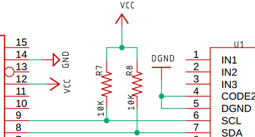
This IC transmits and receives data from the microcontroller via SCL and SDA lines. The SDA and SCL make up the bus interface. These lines must be pulled high by two 4.7K resistors in order to ensure stable operation.
Before we go to the actual hardware operation, here is the detailed functional description of the IC. if you don't want to know all this, you can skip this part because all the functional part is managed by the Arduino library.
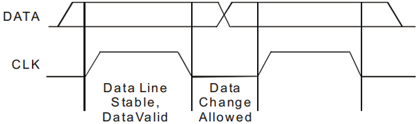
Data Validation
- The data on the SDA line is considered stable when the SCL signal is HIGH.
- The HIGH and LOW states of the SDA line changes only when the SCL is LOW.
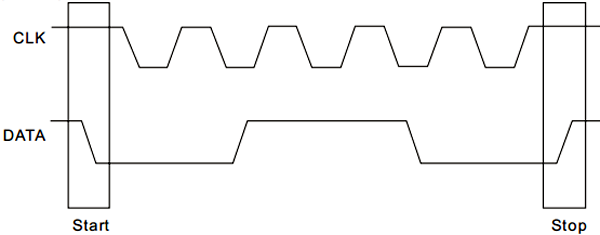
Start and Stop Condition
A Start Condition is activated when
- the SCL is set to HIGH and
- SDA shifts from HIGH to LOW State.
The Stop Condition is activated when
- SCL is set to HIGH and
- SDA shifts from LOW to HIGH State
Note! This information is very useful for debugging the signals.
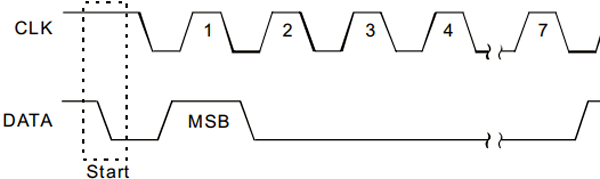
Data Format
Every byte transmitted to the SDA Line consists of 8 bits, which form a byte. Each byte must be followed by an Acknowledge Bit.
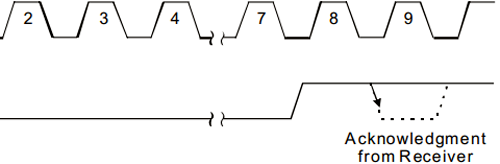
Acknowledgment
Acknowledgment ensures stable and proper operation. During the Acknowledge Clock Pulse, the microcontroller pulls the SDA pin HIGH at this exact moment the peripheral device (audio processor) pulls-down (LOW) the SDA line.
The peripheral device (PT2258) is now addressed & it has to generate an acknowledge after receiving a byte, otherwise, the SDA line will remain at High level during the ninth (9th) Clock Pulse. If this happens, the master transmitter will generate STOP Information in order to abort the transfer.
That clears the no need to be in place for a valid data transfer.
Address Selection
The I2C address of this IC depends on the state of CODE1 (Pin No.17) and CODE2 (Pin No.4).
|
CODE1 (PIN No. 17) |
CODE2 (PIN No. 4) |
HEX ADDRESS |
|
0 |
0 |
0X80 |
|
0 |
1 |
0X84 |
|
1 |
0 |
0X88 |
|
1 |
1 |
0X8C |
Logic High = 1
Logic Low = 0
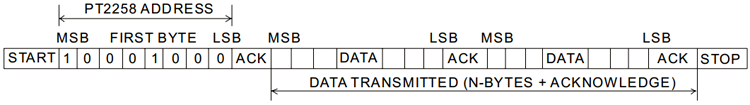
Interface Protocol
The interface protocol consists of the following:
- A Start bit
- A Chip Address Byte
- ACK=Acknowledge bit
- A Data byte
- A Stop bit
A little Housekeeping
After the IC is powered on, it needs to wait at least 200ms before transmitting the first data bit, otherwise, the data-transfer may fail.
After the delay, the first thing to do is to clear the register by sending “0XC0” vi the I2C line, this ensures proper operation.

The above step clears the entire register, now we need to set a value to the register, otherwise, the register stores garbage value and we get a freckled output.
To ensure proper volume adjustments, it is necessary to send a multiple of 10dB followed by a 1dB code to the attenuator in sequence, otherwise, the IC can behave abnormally. The diagram below clarifies it more.
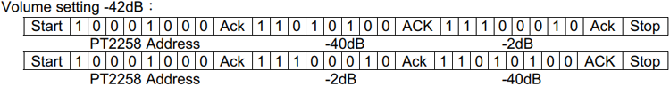
Both the above methods will work properly.
To ensure proper operation, make sure that the I2C data transfer speed never exceeds 100KHz.
That's how you can transmit a byte to the IC and attenuate the input signal. The above section is to learn how the IC functions, but as I have said earlier, we are going to use an Arduino library to communicate with the IC which manages all the hard code, and we just need to make some function calls.
All the above information is taken from the datasheet, please refer to it for further information.
The Schematic

The above image shows the test schematic of the PT2258 based Volume Control Circuit. It’s taken from the datasheet and modified according to need.
For the demonstration, the circuit is constructed on a solderless breadboard with the help of the schematic shown above.
Note! All the components are placed as closely as possible to reduce parasitic capacitance inductance and resistance.
Components Required
- PT2258 IC – 1
- Arduino Nano Controller – 1
- Generic Breadboard – 1
- Screw Terminal 5mm x 3 – 1
- Push Button – 1
- 4.7K Resistor, 5% - 2
- 150K Resistor, 5% - 4
- 10k Resistor, 5% - 2
- 10uF Capacitor – 6
- 0.1uF Capacitor – 1
- Jumper Wires - 10
Arduino Code
For simplicity, I am going to use a PT2258 library from GitHub, which is made by sunrutcon.
This is a very well written library that's why I have decided to use it, but since it is very old, it’s a little buggy and we need to fix it before we can use it.
First, download & extract the library from the GitHub repository.
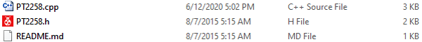
You will get the above two files after extraction.
#include <arduino.h>
#include <wire.h>
#include <PT2258.h>
Next, open the PT2258.cpp file with your favorite Text Editor, I am using Notepad++.
You can see that the “w” of the wire library is in small letters, which is incompatible with the latest Arduino versions, & you need to replace it with a caps “W”, that's it.
Complete code for the PT2258 Volume Controller can be found at the end of this section. Here important parts of the program are explained.
We start the code by including all the required libraries files. The Wire library is used to communicate between the Arduino and the PT2258. The PT2258 library contains all the critical I2C timing information and acknowledgments. The ezButton library is used to interface with the push-buttons.
Instead of using below code images, Copy all the code instances from code file and make them Formatted like we used to do in other projects
#include <PT2258.h>
#include <ezButton.h>
#include <Wire.h>
Next, make the objects for the two buttons and the PT2258 library itself.
PT2258 pt2258;
ezButton button_1(2);
ezButton button_2(4);
Next, define the volume level. This is the default volume level that this IC will start off with.
Int volume = 40;
Next, initiate the UART, and set the clock frequency for the I2C bus.
Serial.begin(9600);
Wire.setClock(100000);
It’s very important to set the I2C clock, otherwise, the IC will not work because the maximum clock frequency supported by this IC is 100KHz.
Next, we do a little housekeeping with an if else statement in order to ensure the IC is communicating properly with the I2C bus.
If (!pt2258.init())
 Serial.printIn(“PT2258 Successfully Initiated”);
Else
 Serial.printIn(“Failed to Initiate PT2258”);
Next, we set the debounce delay for the pushbuttons.
Button_1.setDebounceTime(50);
Button_2.setDebounceTime(50);
Finally, initiate the PT2258 IC by setting it up with the default channel volume and Pin number.
/* Iniciating PT with default volume and Pin*/
Pt2258.setChannelVolume(volume,4);
Pt2258.setChannelVolume(volume,5);
This marks the end of the Void Setup() section.
In the Loop section, we need to call the loop function from the button class; it's a library norm.
Button_1.loop(); //Library norms
Button_2.loop(); //Library norms
The below if section is to decrease the volume.
/* if button 1 is pressed if condition is true */
If (button_1.ispressed())
{
   Volume++; // Incrementing the volume counter.
   // This if statement ensures the volume does not goes above 79
   If (volume >= 79)
   {
   Volume = 79;
   }
   Serial.print(“volume: “); // printing the volume level
   Serial.printIn(volume);
   /* set the volume for channel 4
   Which is in PIN 9 of the PT2558 IC
  */
  Pt2558.setChannelVolume(volume,4);
  /*set the volume for channel 5
  Which is the PIN 10 of the PT2558 IC
  */
  Pt2558.setChannelVolume(volume,5);
}
The below if section is to increase the volume.
// The same happens for the button 2
If (button_2.isPressed())
{
Volume--;
// this if statement ensures the volume level does not go below zero.
If (volume <= 0)
Volume = 0;
Serial.print(“volume: “);
Serial.printIn(volume);
Pt2258.setChannelVolume(volume,4);
Pt2558.setChannelVolume(volume,5);
}

Testing the Digital Audio Volume Control Circuit
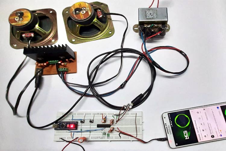
To test the circuit, the following apparatus was used
- A transformer which has a 13-0-13 Tap
- 2 4Ω 20W speaker as a load.
- Audio source (Phone)
In a previous article, I have shown you how to make a Simple 2x32 Watt Audio Amplifier with TDA2050 IC, I am going to use that for this demonstration also.
I have disordered the mechanical potentiometer and shorted two leads with two small jumper cables.
Now, with the help of two push-buttons, the volume of the amplifier can be controlled.
Further Enhancement
The circuit can be further modified in order to improve its performance. Improvements like the circuit can be made to a PCB to further eliminate the noise generated by the digital section of the IC. We can also add an additional filter in order to reject high-frequency noises. Also, check out other Audio Amplifier circuits and other Audio related projects.
I hope you liked this article and learned something new out of it. If you have any doubt, you can ask in the comments below or can use our forums for detailed discussion.
Complete Project Code
#include <PT2258.h>
#include <ezButton.h>
#include <Wire.h>
PT2258 pt2258; // PT2258 Object
ezButton button_1(2); //Button_1 Object
ezButton button_2(4); //Button_2 Object
int volume = 40; // Default volume / Starting Volume
void setup() {
  Serial.begin(9600); //UART begin
  Wire.setClock(100000); // setting the I2C clock to 100KHz
  /* checking if the MCU can talk with the PT or not*/
  if (!pt2258.init())
    Serial.println("PT2258 Successfully Initiated");
  else
    Serial.println("Failed to Initiate PT2258");
  /* Setting up button debounce delay*/
  button_1.setDebounceTime(50);
  button_2.setDebounceTime(50);
  /* Initiating PT with default volume and Pin*/
  pt2258.setChannelVolume(volume, 4);
  pt2258.setChannelVolume(volume, 5);
}
void loop() {
  button_1.loop(); //Library norms
  button_2.loop(); //Library norms
  /* If button 1 is pressed if condition is true*/
  if (button_1.isPressed())
  {
    volume++; // Incrementing the volume counter.
    // this if statement ensures the volume does not goes above 79
    if (volume >= 79)
    {
      volume = 79;
    }
    Serial.print("volume: "); // Printing the volume level
    Serial.println(volume);
    /*Set the volume for channel 4
      Which is in PIN 9 of the PT2258 IC
    */
    pt2258.setChannelVolume(volume, 4);
    /*Set the volume for channel 5
       Which is the Pin 10 of the PT2258 IC
    */
    pt2258.setChannelVolume(volume, 5);
  }
  //The same happens for the button 2
  if (button_2.isPressed())
  {
    volume--;
    // this if statement ensures the volume level doesn't go below zero.
    if (volume <= 0)
      volume = 0;
    Serial.print("volume: ");
    Serial.println(volume);
    pt2258.setChannelVolume(volume, 4);
    pt2258.setChannelVolume(volume, 5);
  }
}
Hi
i have tried all the steps and observed that nothing is working
in case it is failed to initialize, the message should print
i have noticed one thing, i have checked the address of it using I2c scanner, it shows address is "0x44" but in IC pin 17 is Vcc (means 1) and Pin 4 is ground (means 0) so the address should be "0x88" right?
Please help me to resolve this