
In simple language, Tone Control Circuit is the circuit, using which we can control the output of audio device. To control the output means we can control the Volume, Treble and Bass of the Audio output. So, to achieve this aim we have to control the output frequency. If we can control output frequency than our aim is achieved!
To control the output frequency, we have to use some kinds of filters, which only allow the signals of some particular frequency range and block the other signals. For this purpose, we have two types of filters,
- High Pass Filter
- Low Pass Filter
High Pass Filter:
A high-pass filter (HPF) is an electronic filter that allows passing the signals of frequency higher than the cut off frequency and blocks all the other lower frequency signals which are lower than the cut off frequency. It is also low-cut filter or bass-cut filter. It is used to remove the noise from the sound and used in audio amplifier circuits.
Low Pass Filter:
A low-pass filter (LPF) is a filter that allows passing the signals of frequency lower than the cut off frequency and blocks all the other higher frequency signals which are higher than the cut off frequency. The exact frequency response of the filter depends on the filter design. Its ia also high-cut filter or treble-cut filter in audio applications. A low-pass filter is just opposite of a high-pass filter.
Now, what is audio signal? So, audio signal is nothing but the combination of low frequencies and high frequencies. Bass is referred as lower frequency range tones or low notes. And Treble is referred for the high frequencies range tones or higher notes. So in this article, we will explain how to control Bass, Treble and volume using audio tone control circuit.
This circuit needs minimum number of components, is very cost effective and most of the components required can be found from your junk box.
Components Required:
Name of component | Number of component | |
TL072 OP-AMP | 1 | |
100k plot (variable resister) | 3 | |
Resisters: | 2.2 MΩ (R1) | 1 |
| 10 kΩ (R2, R3) | 2 |
| 100kΩ (R4, R5) | 2 |
| 1 kΩ (R6, R7) | 2 |
Capacitors: | 100 pF (C1) | 1 |
| 1 μF (C2) | 1 |
| 2.2 μF (C3) | 1 |
| 22 nF (C4, C5) | 2 |
| 220 nF (C6) | 1 |
| 2.2 nF (C7) | 1 |
Dual Power Supply Circuit for Op-Amp in Tone Controller:
For OP-AMP in the Audio Tone Controller Circuit, we require two supplies, +15V and -15V. We can get both supplies from dual power supply circuit. Connection diagram of this circuit is shown below. We are using IC7815 and IC7915 to get the +15 Volt and -15 Volts. This +15 Volt and -15 Volt is given to the TL072C.

We have used 12-0-12 transformer to generate the 15v from the 230v AC supply. Transformer will step down the voltage from 230 Volt to the 12 Volt. Here we are connecting the Bridge rectifier using diode IN4007. This will rectify the 12 volt supply. We are connecting the 2 capacitors of the 2200μF, 25V for a filtering purpose. Then it is given to the IC7815 and IC7915. IC 7815 gives us the +15Volt and IC7915 gives us the -15 Volt. That’s how Dual supply is working.
Circuit Diagram and Explanation:

Here we can see that the audio input is given to the circuit and the after we are using the low pass filter and high pass filter, explanation of high pass filter and low pass filter is given below. Here from the Dual Supply we get the +15Volt and - 15Volt supply which is further given to the TL072 Op-amp. Here +15 Volts is given to the 8th terminal and -15 Volts is given to the 4th terminal of TL072 opamp. The audio input is given to the 3rd terminal of TL072 and we get the output from the terminal 1 of TL072. Then this output is given to the Variable Resistors (pot). And with this Pots we can change the Volume, Treble and Bass. The output is produced through normal Speaker. Here we have used the low watt speaker that’s why the output sound is low, check the Video given at the end.
Here we have connected Three potentiometers to control the Volume, Bass, and Treble. As you rotate the potentiometer knob, the corresponding parameter (volume, treble and bass) will be changed accordingly.
Working of Audio Tone Control Circuit:
Audio tone control circuit is mainly used for controlling the signal bandwidth and to satisfy music. We can divide this into two parts: Amplifier Circuit and Tone Controller circuit.
Amplifier Circuit:
It consists of TL072 non-inverting operational amplifier. R3 resistor is used for the feedback and Resistor R4 is connected to ground. These two resistors (R3 and R4) control the gain of operational amplifier. The gain would be Av = 1+ (R3 / R4). To decrease the offset effect on the operational amplifier output, resistor R2 is used.
Capacitor C2 is used here as a decoupling capacitor as well as to cut off the low frequencies.
Tone Controller Circuit:
Variable resistor RV1 is used to control the BASS, RV2 is used to control the Treble and RV3 is used to control the Volume. Resistor R7 gives the isolation between Bass and Treble.
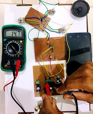
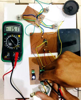
To operate the circuit, connect the components as per the circuit diagram, give +15v and -15v supply to TL072 opamp and give audio input from mobile by connecting 3.5 mm audio jack to the circuit. Now you can control the Bass, Treble and Volume by rotating three potentiometer on the circuit.
As application of this Tone Controller Circuit, it can be used to build a speaker in very cheap price. It is easy to implement and if we use the speaker of higher watts, it will give good output also.

I tried several times to make it in proteus software but i dont get the sound out put i cant hear the sound so i cant adjust the valume, bass and treble