
Interrupts is a mechanism by which an I/O or an instruction can suspend the normal execution of processor and gets itself serviced like it has highest priority. Like for example, a processor doing a normal execution can also continuously monitor for some kind of event or an interrupt to happen. That is when an external interrupt is happened (like from some sensor) then the processor pause its normal execution and first serves the interrupt and then continue its normal execution.
Here in this project, for understanding the Interrupts in STM32F103C8, we will use push button as external interrupt. Here we will increment a number from 0 and display it on 16x2 LCD, and whenever the push button is pressed the led turns ON and the LCD display shows INTERRUPT. LED turns off as soon as the button is released.
Types of Interrupts and ISR
Interrupts can be broadly classified into two types:
Hardware Interrupts: If the signal to the processor is from some external device such as button or sensor or from some other hardware device which generates a signal and tell processor to do particular task present in ISR is known as hardware interrupts.
Software Interrupts: The interrupts which are generated by the software instructions.
Interrupt Service Routine
Interrupt Service Routine or an Interrupt handler is an event that has small set of instructions in it and when an interrupt is occurred the processor first executes these code that is present in ISR and then continue with the task which it was doing before the interrupt.
Syntax for Interrupt in STM32
ISR has following syntax attachInterrupt (digitalPinToInterrupt(pin), ISR, mode) in Arduino and the same can also be used in STM32 as we use arduino IDE to upload code.
- digitalPinToInterrupt(pin): Like in Arduino board Uno we have pins 2,3 & in mega we have 2,3,18,19,20,21 for interrupts. In STM32F103C8 we also have interrupt pins any GPIO pins can be used for interrupts. We just to specify the input pin that we are using for interrupt. But while using more than one interrupts at the same time we may need to follow some restrictions.
- ISR: It a Interrupt handler function that is called when an external interrupt is occurred. It has no arguments and void return type.
- Mode: Type of transition to trigger the interrupt
- RISING: To trigger an interrupt when the pin transits from LOW to HIGH.
- FALLING: To trigger an interrupt when the pin transits from HIGH to LOW.
- CHANGE: To trigger an interrupt when the pin transits either from LOW to HIGH or HIGH to LOW (i.e., when the pin changes).
Some conditions while using interrupt
- Interrupt Service Routine function (ISR) must be as short as possible.
- Delay () function doesn’t work inside ISR and should be avoided.
Components Required
- STM32F103C8
- Push button
- LED
- Resistor (10K)
- LCD (16x2)
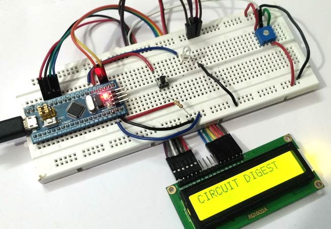
Circuit Diagram and Connections

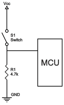
One side of the push button pin is connected to 3.3V of STM32 and the other side is connected to input pin (PA0) of STM32 via a pull down resistor.
Pull Down resistor is used so that microcontroller will only get either HIGH or LOW at its input when button is pressed or released. Otherwise, without pull down resistor, MCU may get confuse and feed some random floating values to the input.
Connection between STM32F103C8 and LCD
The following table shows the pin connection between LCD (16X2) and the STM32F103C8 microcontroller.
|
STM32F103C8 |
LCD |
|
GND |
VSS |
|
+5V |
VDD |
|
To Potentiometer Centre PIN |
V0 |
|
PB0 |
RS |
|
GND |
RW |
|
PB1 |
E |
|
PB10 |
D4 |
|
PB11 |
D5 |
|
PC13 |
D6 |
|
PC14 |
D7 |
|
+5V |
A |
|
GND |
K |

Programming STM32F103C8 for interrupts
Program for this tutorial is simple and given at the end of this tutorial. We don’t need FTDI programmer to program STM32, simply connect your PC to USB port of STM32 and start programming with Arduino IDE. Learn more about programming STM32 through USB port.
As we said that here in this tutorial we are going to increment a number from 0 and display it in on 16x2 LCD and whenever a push button is pressed the led goes ON and LCD display shows ‘INTERRUPT’.
First define LCD pins connections with STM32. You can modify it as per your requirements.
const int rs= PB10,en= PB11,d4= PB0,d5= PB1,d6= PC13,d7= PC14;
Next, we include the header file for the LCD display. This calls the library which contains the code for how the STM32 should communicate with the LCD. Also make sure the function LiquidCrystal is called with the pin names that we just defined above.
include<LiquidCrystal.h>
LiquidCrystal lcd (rs,en,d4,d5,d6,d7);
Global variables are used to pass data between ISR and the main program. We declare the variable ledOn as volatile and also as Boolean to specify True or False.
volatile boolean ledOn = false;
Inside the void setup() function, we will display a intro message and clear it after 2 seconds.
lcd.begin(16,2);
lcd.print("CIRCUIT DIGEST");
delay(2000);
lcd.clear();
Again in same void setup () function, we need to specify the input and output pins. We set pin PA1 for output to LED and PA0 for input from push button.
pinMode(PA1,OUTPUT)
pinMode(PA0,INPUT)
We are also going to increment a number, so declare a variable with value zero.
int i = 0;
Now the important part of the code is attachInterrupt() function, it is also included inside the void setup()
attachInterrupt(digitalPinToInterrupt(PA0),buttonPressed,CHANGE)
We specified the pin PA0 for external interrupt, and buttonPressed is the function which is to be called when there is CHANGE (LOW to HIGH or HIGH to LOW) in PA0 pin. You can also use any other function name, pin and mode according to requirement.
Inside the void loop() we increment a number (i) from zero and print the number in LCD(16x2).
lcd.clear();
lcd.print("NUMBER:");
lcd.print(i);
++i;
delay(1000);
The most important part is creating a interrupt handler function according to the name that we used in the attachInterrupt() function. We used buttonPressed so here we have created a function void buttonPressed()
void buttonPressed()
{
  if(ledOn)
  {
     ledOn=false;
     digitalWrite(PA1,LOW);
  }
  else
  {
     ledOn = true;
     digitalWrite(PA1,HIGH);
     lcd.setCursor(0,1);
     lcd.print("Interrupt");
  }
}
Working of this buttonPressed() ISR:
According to the value of ledOn variable, the LED turns ON and OFF.
|
BUTTON STATE |
ledOn(Value) |
LED(Red) |
LCD(16x2) |
|
UNPRESSED |
False |
OFF |
- |
|
PRESSED |
True |
ON |
Shows ‘’INTERRUPT’ |
If the ledOn value is false then LED remains turned off and if the ledOn value is True then LED turns on and LCD display shows ‘Interrupt’ on it.
NOTE: There may be switch debounce effect sometimes and it may count multiple trigger when pushbutton is pressed, this is because several spikes in voltage due to mechanical reason of switching push button. This can be reduced by introducing RC filter.
The complete working of interrupts in STM32F103C8 is shown in the below video.
Complete Project Code
//INTERRUPTS IN STM32F103C8
//CIRCUIT DIGEST
const int rs= PB10,en= PB11,d4= PB0,d5= PB1,d6= PC13,d7= PC14;    //  declaring pin names and pin numbers of lcd
#include<LiquidCrystal.h>                                         //  including lcd display library
LiquidCrystal lcd (rs,en,d4,d5,d6,d7);                            //  setting lcd and its parameters
volatile boolean ledOn = false;                                   //  variable declared as global
void setup()
{
  lcd.begin(16,2);                                                //  setting LCD as 16x2 type
  lcd.print("CIRCUIT DIGEST");                                    //  puts CIRCUIT DIGEST IN LCD
  delay(2000);                                                    //  delay time
  lcd.clear();                                                    //  clears lcd display
  pinMode(PA1,OUTPUT);                                            //  set pin PA1 as output
  pinMode(PA0,INPUT);                                             //  set pin PA0 as input
  int i = 0;                                                        //  declare variable i and initiliaze with 0
  attachInterrupt(PA0,buttonPressed,CHANGE);                      //  function for creating external interrupts
}
void loop()                                                       //  void loops runs continuously
{
  lcd.clear();                                                    //  clears lcd display
  lcd.print("NUMBER:");                                           //  puts NUMBER: in LCD display
  lcd.print(i);                                                   //  prints the values of i in LCD
  ++i;                                                            //  increments value of i
  delay(1000);                                                    //  delays time
 }
void buttonPressed()                                              //
{
  if(ledOn)                                                       //  if statement depends on LedOn value
  {
     ledOn=false;                                                 //  Makes ledOn false if it is True
     digitalWrite(PA1,LOW);                                       //  digital writs the low vale to PA1 pin makes led OFF
  }
  else
  {
     ledOn = true;                                                //  Makes ledOn True if it is False
     digitalWrite(PA1,HIGH);                                      //  digital writs the HIGH vale to PA1 pin makes led ON
     lcd.setCursor(0,1);                                          //  sets cursor at first column and second row
     lcd.print("Interrupt");                                      //  puts INTERRUPT in LCD display
  }
}

1. What is the purpose of the potentiometer used in the circuit?
2. What is the difference between using potentiometer and Ground for the V0/VEE pin (Like in this tutorial of CircuitDigest: https://circuitdigest.com/microcontroller-projects/interfacing-stm32f103c8t6-blue-pill-board-with-lcd-display) ?
3. Can the digital pins be shuffled (as they are used differently in the above linked tutorial)? Do they have special reason (as Rx3, Tx3 etc.) for their pin assignment?