

The advancement in Electric Vehicles, Drone and other mobile electronics like IoT Devices seems to be promising for the future. One common thing among all these is that they are all powered by batteries. Following Moore’s law the electronic devices tend to become smaller and more potable, these portable devices should have their own source of power to operate. The most common battery choice for portable electronics today is Lithium Ion or Lithium Polymer Batteries. While these Batteries have a very good charge density they are chemically unstable under harsh conditions hence care should be taken while charging them and using them.
In this project we will build a Two Stage Battery charger (CC and CV) that could be used as to charge Lithium ion or lithium polymer batters. The battery charger circuit is designed for 7.4V lithium battery pack (two 18650 in Series) which I commonly use in most robotics project but the circuit can be easily modified to fit in lower or slightly higher battery Packs like to build 3.7 lithium battery charger or 12v lithium ion battery Charger. As you might know there are ready made Chargers available for these batteries, but those that are cheap are very slow and those that are fast are very expensive. So in this circuit I decided to build a simple crude charger with LM317 ICs with CC and CV mode. Also, what’s more fun than building your own gadget and learning in it’s process.
Remember that Lithium batteries should be handled carefully. Overcharging it or Shorting it might lead to explosion and fire hazard, so stay safe around it. If you are completely new to lithium batteries then I would strongly advise you to read through the Lithium battery article, before proceeding further. That being said let’s get into the project. Also if you are looking for a a simple lithium battery charger circuit then check this 18650 Lithium Battery Charger using TP4056.
CC and CV mode for Battery Charger:
The Charger that we intent to build here is a Two Step Charger, meaning it will have two charging modes namely Constant Charge (CC) and Constant Voltage (CV). By combining these two modes we will be able to charge the battery faster than usual.
Constant Charge (CC):
The first mode to get into operation will be the CC mode. Here the amount of charging current that should enter the battery is fixed. To maintain this current the voltage will be varied accordingly.
Constant Voltage (CV):
Once the CC mode is completed the CV mode will kick in. Here the Voltage will be kept fixed and the current will be allowed to vary as per the charging requirement of the battery.
In our case we have a 7.4V Lithium battery pack, which is nothing but two 18650 cells of 3.7V each is connected in series (3.7V + 3.7V = 7.4V). This battery pack should be charged when the voltage reaches down to 6.4V (3.2V per cell) and can be charged upto 8.4V (4.2V per cell). Hence these values are already fixed for our battery pack.
Next we have decided the charging current in CC mode, this can normally found in the datasheet of the battery and the value depends on the Ah rating of the battery. In our case I have decided a value of 800mA as Constant Charging current. So initially when the battery is connected for charging the charger should get into CC mode and push in 800mA into the battery by varying the charging voltage according. This will charge the battery and the battery voltage will start to increase slowly.
Since we are pushing a heavy current into the battery with higher voltage values we cannot leave it in CC till the battery gets fully charged. We have to shift the charger from CC mode to CV mode when the battery voltage has reached a considerable value. Our battery pack here should be 8.4V when fully charged so we can shift it from CC mode to CV mode at 8.2V.
Once the charger has shifted to CV mode we should maintain a constant voltage, the value of constant voltage is 8.6V in our case. The battery will drain a considerably less current in CV mode than CC mode since the battery is almost charged in CC mode itself. Hence at a fixed 8.6V the battery will consume less current and this current will go reduce as the battery gets charged. So we have to monitor the current when it reaches a very low value say less than 50mA we assume that the battery is fully charged and disconnect the battery from the charger automatically using a relay.
To summarize we can list the battery charging procedure as follows
- Enter CC mode and charge the battery with a fixed 800mA Regulated current.
- Monitor the battery voltage and when it reaches 8.2V shift to CV Mode.
- In CV mode charge the battery with a fixed 8.6V Regulated Voltage.
- Monitor the charging current as it gets reduced.
- When the current reaches 50mA disconnect the battery from charger automatically.
The values, 800mA, 8.2V and 8.6V are fixed because we have a 7.4V lithium battery pack. You can easily change these values as per the requirement of your battery pack. Also note that there exist many stage chargers. A two stage charger like this is the most commonly used one. In a three stage charger the stages will be CC, CV and float. In a four or six stage charger the internal resistance, temperature etc will be considered. Now, that we have a brief understanding of how the Two step charger should actually work, let’s get into the Circuit Diagram.
Circuit Diagram
The complete circuit diagram for this Lithium Ion Battery Charger can be found below. The circuit was made using EasyEDA and the PCB will also be fabricated using the same.

As you can see the circuit is pretty simple. We have used two LM317 Variable voltage regulator ICs, one to regulate Current and the other to regulate Voltage. The first relay is used to switch between CC and CV mode and the second relay is used to connect or disconnect the battery to the charger. Let’s break the circuit into segments and understand its design.
LM317 Current Regulator
The LM317 IC can act as a current regulator with the help of a single resistor. The circuit for the same is shown below
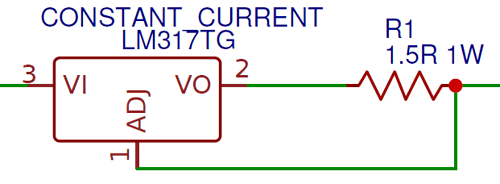
For our charger we need to regulate a current of 800mA as discussed above. The formula for calculating the value of resistor for the required current is given in datasheet as
Resistor (Ohms) = 1.25 / Current (Amps)
In our case the value of current is 0.8A and for that we get a value of 1.56 Ohms as the resistor value. But the closest value we could use is 1.5 Ohms which is mentioned in the circuit diagram above.
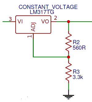
LM317 Voltage Regulator
For the CV mode of lithium battey charger we have to regulate the voltage to 8.6V as discussed earlier. Again LM317 can do this with the help of just two resistors. The circuit for the same is shown below.
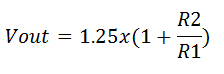
The formula to calculate the output voltage for a LM317 Regulator is give as
In our case the output voltage (Vout) should be 8.6V, and the value of R1 (here R2) should be less than 1000 ohms so I have selected a value of 560 Ohms. With this if we calculate the value of R2 we get it to be 3.3k Ohms. Alternatively you can use any values of resistor combination provided you get the output voltage to be 8.6V. You can use this online LM317 Calculator to make your work easier. Also learn more about LM317 IC here.
Relay Arrangement to toggle between CC and CV mode
We have two 12V Relay, each of which are driven by Arduino through BC547 NPN transistor. Both the Relay arrangement is shown below
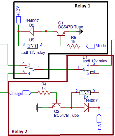
The First Relay is used to toggle between the CC and CV mode of the charger, this Relay is triggered by the Arduino pin labeled as “Mode”. By default the relay is in CC mode when it is triggered it changes from CC mode to CV mode.
Similarly the second Relay is used to connect or disconnect the charger from the Battery; this Relay is triggered by the Arduino pin labeled as “Charge”. By default the relay disconnects the battery from the charger, when triggered it connects the charger to the battery. Apart from this the two diodes D1 and D2 are used for protecting the circuit from reverse current and the 1K Resistors R4 and R5 are used to limit the current flowing through the base of the transistor.

Measuring Lithium Battery Voltage
To monitor the charging process we have to measure the battery voltage, only then we can shift the charger from CC mode to CV mode when the battery voltage reaches 8.2V as discussed. The most common technique used to measure voltage with Microcontrollers like Arduino is by using a Voltage divider circuit. The one used here is shown below.
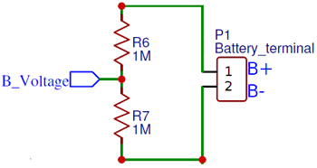
As we know the maximum voltage the Arduino Analog pin can measure is 5V, but our battery could go as high as 8.6V in CV mode so we need to step down this to a lower voltage. This is exactly done by the Voltage divider circuit. You can calculate the value of Resistor and know more about voltage divider by using this online voltage divider calculator. Here we have deduced the output voltage by half of the original input voltage, this output voltage is then sent to the Arduino Analog pin though the “B_Voltage” label. We can later retrieve the original value while programming the Arduino.
Measuring Charging Current
Another vital parameter to be measured is the charging current. During the CV mode the battery will be disconnected to the charger when the charging current goes below 50mA indicating charge completion. There are many methods to measure current, the most commonly used method is by using a shunt resistor. The circuit for the same is shown below
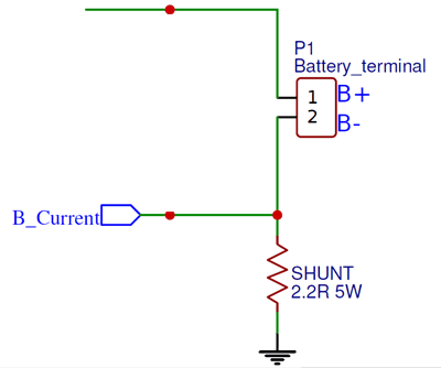
The concept behind it is simple ohms law. The entire current flowing to the battery is made to flow through the shunt resistor 2.2R. Then by Ohms law (V=IR) we know that the voltage drop across this resistor will be proportional to current flowing through it. Since we know the value of resistor and Voltage across it can be measured using Arduino Analog pin the value of current can be easily calculated. The value of voltage drop across the resistor is sent to Arduino through the label “B_Current”. We know that the maximum charging current will be 800mA so by using the formulae V=IR and P=I2R we can calculate the Resistance value and Power value of the Resistor.
Arduino and LCD
Finally on the Arduino side we have to interface an LCD with Arduino to display the charging Process to the user and control the charging by measuring the voltage, current and then triggering the Relays accordingly.
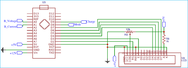
The Arduino Nano has an on-board Voltage regulator hence the supply voltage is provided to Vin and the regulated 5V is used to run the Arduino and 16x2 LCD display. The Voltage and Current can be measured by the Analog pins A0 and A1 respectively using the labels “B_Voltage” and “B_Current”. The Relay can be triggered by toggling the GPIO pin D8 and D9 which are connected through the labels “Mode” and “Charge”. Once the schematics are ready we can proceed with PCB fabrication.
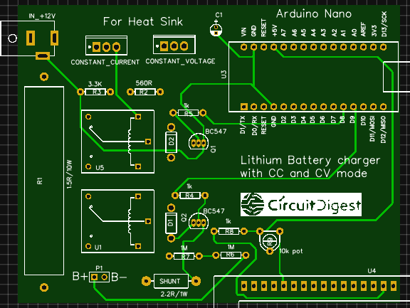
PCB Design and Fabrication using EasyEDA
To design this Lithum battery charger Circuit, we have chosen the online EDA tool called EasyEDA. I have previously used EasyEDA many times and found it very convenient to use since it has a good collection of footprints and it is open-source. After designing the PCB, we can order the PCB samples by their low cost PCB fabrication services. They also offer component sourcing service where they have a large stock of electronic components and users can order their required components along with the PCB order.
While designing your circuits and PCBs, you can also make your circuit and PCB designs public so that other users can copy or edit them and can take benefit from your work, we have also made our whole Circuit and PCB layouts public for this circuit, check the below link:
https://easyeda.com/CircuitDigest/7.4V-Lithium-Charger-with-MCU
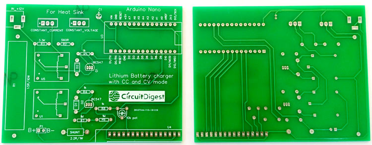
You can view any Layer (Top, Bottom, Topsilk, bottomsilk etc) of the PCB by selecting the layer form the ‘Layers’ Window. You can also view the Lithium battery Charger PCB, how it will look after fabrication using the Photo View button in EasyEDA:
Calculating and Ordering Samples online
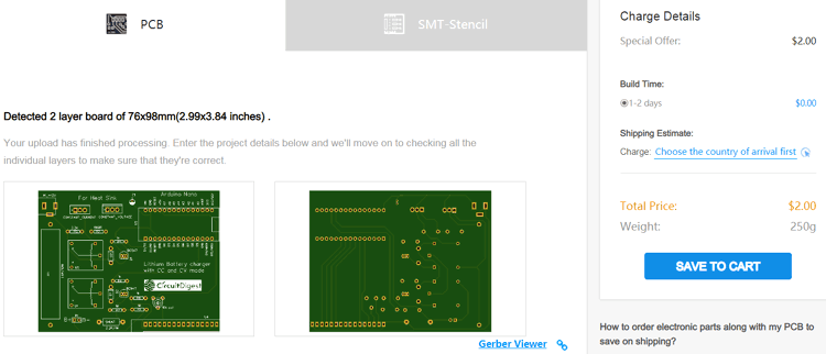
After completing the design of this Lithium battery Charger PCB, you can order the PCB through JLCPCB.com. To order the PCB from JLCPCB, you need Gerber File. To download Gerber files of your PCB just click the Generate Fabrication File button on EasyEDA editor page, then download the Gerber file from there or you can click on Order at JLCPCB as shown in below image. This will redirect you to JLCPCB.com, where you can select the number of PCBs you want to order, how many copper layers you need, the PCB thickness, copper weight, and even the PCB color, like the snapshot shown below:
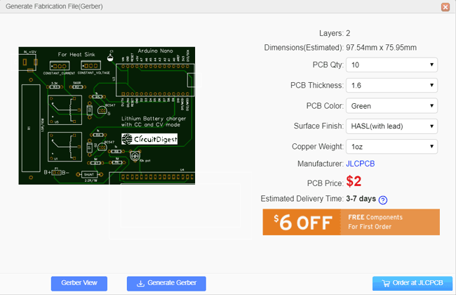
After clicking on order at JLCPCB button, it will take you to JLCPCB website where you can order the PCB in very low rate which is $2. Their build time is also very less which is 48 hours with DHL delivery of 3-5 days, basically you will get your PCBs within a week of ordering.
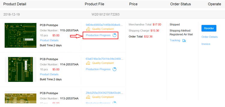
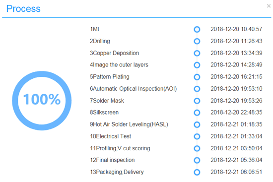
After ordering the PCB, you can check the Production Progress of your PCB with date and time. You check it by going on Account page and click on "Production Progress" link under the PCB like, shown in below image.
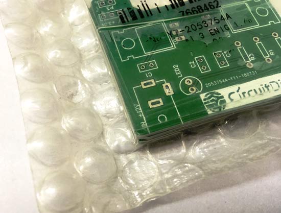
After few days of ordering PCB’s I got the PCB samples in nice packaging as shown in below pictures.

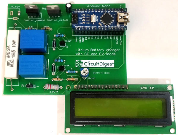
After making sure the tracks and footprints were correct. I proceeded with assembling the PCB, I used female headers to place the Arduino Nano and LCD so that I can remove them later if I need them for other projects. The completely soldered board for Lithium Ion Battery Charger Circuit looks like this below
Programming the Arduino for two step Lithium Battery Charging
Once the hardware is ready we can proceed with writing the code for the Arduino Nano. The complete program for this project is provided at the bottom of the page, you can upload it directly to your Arduino. Now, let’s break the program into small snippets and understand what the code actually does.
As always we begin the program by initializing the I/O pins. As we know from our hardware the pins A0 and A2 is used to measure Voltage and current respectively and the pin D8 and D9 is used the control the Mode relay and Charge relay. The code to define the same is shown below
const int rs = 2, en = 3, d4 = 4, d5 = 5, d6 = 6, d7 = 7; //Mention the pin number for LCD connection
LiquidCrystal lcd(rs, en, d4, d5, d6, d7);
int Charge = 9; //Pin to connect or disconnect the battery to the circuit
int Mode = 8; //Pin to toggle between CC mode and CV mode
int Voltage_divider = A0; //To measure battery Voltage
int Shunt_resistor = A1; //To measure charging current
float Charge_Voltage;
float Charge_current;
Inside the setup function, we initialize the LCD function and display an intro message on the screen. We also define the relay pins as output pins. Then trigger the charge relay connect the battery to the charger and by default the charger stays in CC mode.
void setup() {
  lcd.begin(16, 2); //Initialise 16*2 LCD
  lcd.print("7.4V Li+ charger"); //Intro Message line 1
  lcd.setCursor(0, 1);
  lcd.print("-CircuitDigest "); //Intro Message line 2
  lcd.clear();
  pinMode (Charge, OUTPUT);
  pinMode (Mode, OUTPUT);
  digitalWrite(Charge,HIGH); //Begin Chargig Initially by connecting the battery
  digitalWrite(Mode,LOW); //HIGH for CV mode and LOW of CC mode, initally CC mode
  delay(1000);
}
Next, inside the infinite loop function, we begin the program by measuring the Battery Voltage and Charging current. The value 0.0095 and 1.78 is multiplied with Analog value to convert 0 to 1024 to actual voltage and current value you can use a multimeter and a clamp meter to measure the real value and then calculate the multiplier value. It is also theoretically calculate the multiplier values based on the resistors we have used but it was not as accurate as I expected it to be.
//Measure voltage and current initially
  Charge_Voltage = analogRead(Voltage_divider) * 0.0092; //Measure Battery Voltage
  Charge_current = analogRead(Shunt_resistor) * 1.78; //Measure charging current
If the Charge Voltage is less than 8.2V we enter into CC mode and if it is higher than 8.2V then we enter into CV mode. Each mode has its own while loop. Inside the CC mode loop we keep the Mode pin as LOW to stay in CC mode and then keep monitoring the voltage and current. If the voltage exceeds the 8.2V threshold voltage we break the CC loop using a break statement. The status of charge voltage is also displayed on the LCD inside the CC loop.
//If the battery voltage is less than 8.2V enter CC mode
  while(Charge_Voltage<8.2) //CC MODE Loop
  {
    digitalWrite(Mode,LOW); //Stay in CC mode

//Measure Voltage and Current
    Charge_Voltage = analogRead(Voltage_divider) * 0.0095; //Measure Battery Voltage
    Charge_current = analogRead(Shunt_resistor) * 1.78; //Measure charging current

//print detials on LCD
    lcd.print("V="); lcd.print(Charge_Voltage);
    lcd.setCursor(0, 1);
    lcd.print("In CC mode");
    delay(1000);
    lcd.clear();

//Check if we have to exit CC mode
    if(Charge_Voltage>=8.2) // If yes
    {
      digitalWrite(Mode,HIGH); //Change to CV mode
      break;
    }
  }
The same technique can be followed for CV mode also. If the voltage exceeds 8.2V the charger enters into CV mode by making the Mode pin high. This applies a constant 8.6V across the battery and the charging current is allowed to vary based on battery requirement. This charging current is then monitored and when it reaches below 50mA we can terminate the charging process by disconnecting the battery from the charger. To do this we simply have to turn off the Charge relay as show in the code below
//If the battery voltage is greater than 8.2V enter CV mode
  while (Charge_Voltage>=8.2) //CV MODE Loop
  {
    digitalWrite(Mode,HIGH); //Stay in CV mode

//Measure Voltage and Current
    Charge_Voltage = analogRead(Voltage_divider) * 0.0092; //Measure Battery Voltage
    Charge_current = analogRead(Shunt_resistor) * 1.78; //Measure charging current

//Display details to user in LCD
    lcd.print("V="); lcd.print(Charge_Voltage);
    lcd.print("  I="); lcd.print(Charge_current);
    lcd.setCursor(0, 1);
    lcd.print("In CV mode");
    delay(1000);
    lcd.clear();

//Check if the battery is charged by monitoring charging current
    if(Charge_current<50) //If yes
    {
      digitalWrite(Charge,LOW); //Turn off charging

      while(1) //Keep the charger off until restart
      {
        lcd.setCursor(0, 1);
        lcd.print("Charge Complete.");
        delay(1000);
        lcd.clear();
      }
    }
  }
}
Working of 7.4V Two Step Lithium Battery Charger
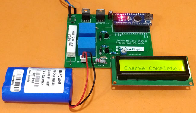
Once the hardware is ready upload the code into the Arduino board. Then connect the battery to the charging terminal of the board. Make sure you connect them in right polarity, reversing the polarity will cause serious damage to the battery and the board. After connecting the battery power the charger using a 12V Adapter. Your will be greeted with an intro text and the charger will proceed to CC mode or CV mode based on the status of the battery. If the battery is fully discharged at the time of charging it will enter into CC mode and your LCD will display something like this below.
As the battery gets charged the Voltage will increase as shown in the video below. When this voltage reaches 8.2V the charger will enter into CV mode from CC mode and now it will display both Voltage and current as shown below.
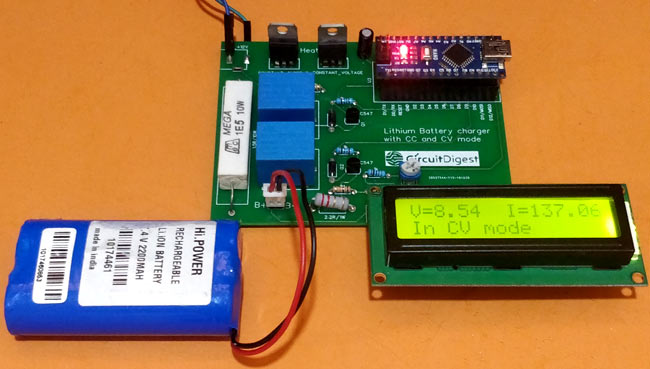
From here slowly the current consumption of the battery will go down as it gets charged. When current reaches to 50mA or less the charger assumes the battery to be fully charged and then disconnects the battery from charger using the relay and displays the following screen. After which you can disconnect the battery from the charger and use it in your applications.
Hope you understood the project and enjoyed building it, this complete board can be used as handy Lithium Ion Battery Charging Module. The complete working can be found in the video below. If you have any questions post them in the comment section below of the use the forums for other technical queries. Again the circuit is only for educational purpose so use it with responsibility since lithium batteries are not stable under harsh conditions.
Complete Project Code
/*

 * 7.4V Lithium Two step Charger Code

 * By: Aswinth Raj

 * For: www.circuitdigest.com

 * Dated: 11-1-2019

 */
#include <LiquidCrystal.h> //Librarey to use 16*2 LCD display
const int rs = 2, en = 3, d4 = 4, d5 = 5, d6 = 6, d7 = 7; //Mention the pin number for LCD connection

LiquidCrystal lcd(rs, en, d4, d5, d6, d7);
int Charge = 9; //Pin to connect or disconnect the battery to the circuit

int Mode = 8; //Pin to toggle between CC mode and CV mode

int Voltage_divider = A0; //To measure battery Voltage

int Shunt_resistor = A1; //To measure charging current

float Charge_Voltage;

float Charge_current;

void setup() {

  lcd.begin(16, 2); //Initialise 16*2 LCD


  lcd.print("7.4V Li+ charger"); //Intro Message line 1

  lcd.setCursor(0, 1);

  lcd.print("-CircuitDigest "); //Intro Message line 2

  lcd.clear();
  pinMode (Charge, OUTPUT);

  pinMode (Mode, OUTPUT);
  digitalWrite(Charge,HIGH); //Begin Chargig Initially by connecting the battery

  digitalWrite(Mode,LOW); //HIGH for CV mode and LOW of CC mode, initally CC mode
  delay(1000);

}

void loop() {
//Measure voltage and current initially

  Charge_Voltage = analogRead(Voltage_divider) * 0.0092; //Measure Battery Voltage

  Charge_current = analogRead(Shunt_resistor) * 1.78; //Measure charging current
//If the battery voltage is less than 8.2V enter CC mode

  while(Charge_Voltage<8.2) //CC MODE Loop

  {

    digitalWrite(Mode,LOW); //Stay in CC mode
//Measure Voltage and Current

    Charge_Voltage = analogRead(Voltage_divider) * 0.0095; //Measure Battery Voltage

    Charge_current = analogRead(Shunt_resistor) * 1.78; //Measure charging current
//print detials on LCD

    lcd.print("V="); lcd.print(Charge_Voltage);

    lcd.setCursor(0, 1);

    lcd.print("In CC mode");

    delay(1000);

    lcd.clear();


//Check if we have to exit CC mode

    if(Charge_Voltage>=8.2) // If yes

    {

      digitalWrite(Mode,HIGH); //Change to CV mode

      break;

    }

  }

//If the battery voltage is greater than 8.2V enter CV mode

  while (Charge_Voltage>=8.2) //CV MODE Loop

  {

    digitalWrite(Mode,HIGH); //Stay in CV mode
//Measure Voltage and Current

    Charge_Voltage = analogRead(Voltage_divider) * 0.0092; //Measure Battery Voltage

    Charge_current = analogRead(Shunt_resistor) * 1.78; //Measure charging current
//Display details to user in LCD

    lcd.print("V="); lcd.print(Charge_Voltage);

    lcd.print("  I="); lcd.print(Charge_current);

    lcd.setCursor(0, 1);

    lcd.print("In CV mode");

    delay(1000);

    lcd.clear();


//Check if the battery is charged by monitoring charging current

    if(Charge_current<50) //If yes

    {

      digitalWrite(Charge,LOW); //Turn off charging
      while(1) //Keep the charger off until restart

      {

        lcd.setCursor(0, 1);

        lcd.print("Charge Complete.");

        delay(1000);

        lcd.clear();

      }

    }

  }

}
//**Happy Charging**//
Comments
You should make some changes
You should make some changes in the circuit for using it with 3.7V battery.
What do you mean by 3*3.7V? Are they connected in series or parallel
Calculations
Hi,
I was hoping you would be able to explain where you got the numbers for the multipliers of the shunt resistor and the voltage divder in the arduino code?
Unbalancing
Hi, I noticed that after many charge and discharge cycles, the two batteries become unbalanced, at one it goes to a very high voltage, and the second one remains discharged, and in fact the total usable charge is reduced. I had to add a balance circuit between the two batteries (BQ29200 http://www.ti.com/product/BQ29200 ). Now is good.
Very nice!
A very nice job my friend. I'm in a very similar project using as you two LM317 (one for fixing current, the other for regulating voltage) and I'm regulating output voltage too (from 3.0V upto 3.95V) using Arduinos PWM output injected into the adjust line.
One of my concerns is measuring the battery voltage; I like your solution but I was wondering about the reference voltage used for the reading, because Arduinos 5V reference isn't exactly 5V, it could be 5.5V or 5.3V. My idea is to use a precision voltage reference like TL341 to avoid these offsets.
A part from that, thank you very much for your sharing, it's very good to compare ideas.
I'm sorry, but reading the
I'm sorry, but reading the voltage in CV mode seems completely wrong to me. After switching the MODE relay, the battery is connected to the 8.6V stabilizer. This voltage is divided on the battery and on the current transducer. As the current is still high immediately after switching, we have a large voltage drop on the transducer and therefore a lower voltage is applied to the battery, not 8.6V. Arduino reads the voltage at the battery terminals PLUS the voltage drop on the current transducer. The battery voltage being less than 8.6V, in reality we do not have a CONSTANT VOLTAGE mode. To avoid this situation, you will need to use a HALL transducer as a current transducer, which does not cause voltage drops at the terminals (its series resistance is 1.2 mΩ)

Will you please suggest changes that i need to do for handling above said configuration ( charging of 3*3.7v 2600mAh LiIon batteries) ???
and can we use 2 relay module directly?
I am very much new, so plz explain in detail.
I am using Arduino UNO for the same.
Do reply, it will be extremely useful.
thanks in advance.
Kapil (Student)