

Using one or two Servo with Arduino is Easy but what if we want to use more than one Servo Motors?
Here, we are going to show you that how to control Multiple Servo Motors with Arduino. Connecting multiple Servo Motors with Arduino seems to be easy and but if we connect all the Servos to Arduino supply pins then they won’t work correctly because of lack of enough current to drive all the motors. So you have to use separate power supply for the motors, either it be from some adapters (5v 2A) or from good quality 9v batteries.
Material Required
- Arduino UNO
- Servo Motor
- Power Supply
- Breadboard
- Connecting Wires
Circuit Diagram

What is a Servo Motor?
Before going into detail, first we should know about Servo Motors.
Servo motors are available at different shapes and sizes. A servo motor will have mainly there wires, one is for positive voltage another is for ground and last one is for position setting. The RED wire is connected to power, Black wire is connected to ground and YELLOW wire is connected to signal.

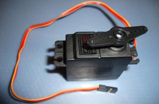
A servo motor is a combination of DC motor, position control system, gears. The position of the shaft of the DC motor is adjusted by the control electronics in the servo, based on the duty ratio of the PWM signal the SIGNAL pin.
Simply speaking the control electronics adjust shaft position by controlling DC motor. This data regarding position of shaft is sent through the SIGNAL pin. The position data to the control should be sent in the form of PWM signal through the Signal pin of servo motor.
The frequency of PWM (Pulse Width Modulated) signal can vary based on type of servo motor. The important thing here is the DUTY RATIO of the PWM signal. Based on this DUTY RATION the control electronics adjust the shaft.
As shown in figure below, for the shaft to be moved to 9o clock the TURN ON RATION must be 1/18.ie. 1ms of ON time and 17ms of OFF time in a 18ms signal.
For the shaft to be moved to 12o clock the ON time of signal must be 1.5ms and OFF time should be 16.5ms. This ratio is decoded by control system in servo and it adjusts the position based on it. This PWM in here is generated by using ARDUINO UNO.
Before Connecting Servos to Arduino, you can test your servo with the help of this Servo Motor Tester Circuit. Also check our below Servo projects:
- Servo Motor Control using Arduino
- Servo Motor Control with Arduino Due
- Servo Motor Interfacing with 8051 Microcontroller
- Servo Motor Control using MATLAB
- Servo Motor Control by Flex Sensor
- Servo Position Control with Weight (Force Sensor)
Arduino Code Explanation
The complete Arduino code for Multiple Servo Control is given at the end.
Arduino has library for Servo Motors and it handles all the PWM related things to rotate the servo, you just need to enter the angle to which you want to rotate and there is function servo1.write(angle); which will rotate the servo to desired angle.
So here we are starting by defining the library for Servo motor.
#include <Servo.h>
In below code, we are initializing all the four servos as Servo1, Servo2, Servo3, and Servo4.
Servo servo1;
Servo servo2;
Servo servo3;
Servo servo4;
Then, we are setting all the servo’s input pin with Arduino. As shown in the below code, Servo1 is connected to the 3rd pin of the Arduino. You can change the pins according to you but keep in mind that it should be a PWM pin. Using a Servo with digital pins of the Arduino is not reliable.
void setup() {
  servo1.attach(3);
  servo2.attach(5);
  servo3.attach(6);
  servo4.attach(9);
}
Now, in the void loop() function we are just rotating all the servo from 0 to 180 degree and then 180 to 0 degree. The delay used in the below code is used to increase or decrease the speed of the servo as it effect the increasing or decreasing speed of variable ‘i’.
void loop() {
  for (int i = 0; i < 180; i++) {
    servo1.write(i);
    servo2.write(i);
    servo3.write(i);
    servo4.write(i);
    delay(10);
  }
  for (i = 180; i > 0; i--) {
    servo1.write(i);
    servo2.write(i);
    servo3.write(i);
    servo4.write(i);
    delay(10);
  }
}
Controlling Multiple Servos with Arduino- Working:
We all face current problem while using more than two servos with one Arduino. The only solution to this is to connect an external power supply with appropriate amount of current rating (in this project I used 2A with 9v supply). For External Power supply you can use Adapters, RPS (Regulated Power Supply Instrument) or good quality 9v volt batteries, evne you can use your laptop USB port for powering small Servo. To use the external supply you just have to short the Arduino ground to external supply ground.
Use the Arduino code given below to program your Arduino and connect all the Servo Motors as shown in the circuit diagram with proper power supply to Motors. Therefore, all servos will work together without any interrupt.
Complete Project Code
#include <Servo.h>
Servo servo1;
Servo servo2;
Servo servo3;
Servo servo4;
int i = 0;
void setup() {
  servo1.attach(3);
  servo2.attach(5);
  servo3.attach(6);
  servo4.attach(9);
}
void loop() {
  for (i = 0; i < 180; i++) {
    servo1.write(i);
    servo2.write(i);
    servo3.write(i);
    servo4.write(i);
    delay(10);
  }
  for (i = 180; i > 0; i--) {
    servo1.write(i);
    servo2.write(i);
    servo3.write(i);
    servo4.write(i);
    delay(10);
  }
}
Comments
I would suggest showinga ubec and showing it connected to a ac/dc plug. I also would suggest to show it completed in a project box with ready servo plugs. Also, the 3.3v, 5v, and the 12v vin could use a multimeter test set on the project box making this an easy test center.
Hy guys i loved your work... but i want to do a minor change. I want to add an switch to make the motor rotate forward and again press dat switch to make it move backward .. plz edit the code and also i need circuit diagram too... thank you in advance
Nice work! Hello, Im new in programming. But may you help me or give suggestion how could I add adjustment if an LDR is involve? I want to make an LDR that will use controll the the rotation of servo so that the LED bulb brightness will adjust. thanks in advance!

I've replicated this project and it works but I would like to apply it to a painting and need to make it autonomous.
Curiously I've tried to connect the 9V battery with respective adapter directly to the arduino power socket but it didn't work, it only works connecting the battery with the cables as shown in your video.
When I disconnect the arduino cable from the computer it stops. It seems it needs the power from the computer + battery to work.
So, how can I make it work without connection to the computer?