
")
In this tutorial we will develop a circuit using Force sensor, Arduino Uno and a servo motor. It will be a servo control system where the servo shaft position is determined by the weight present on the force sensor. Before going any further let’s talk about about the servo and other components.
Servo Motors are used where there is a need for accurate shaft movement or position. These are not proposed for high speed applications. These are proposed for low speed, medium torque and accurate position application. These motors are used in robotic arm machines, flight controls and control systems. Servo motors are also used in some of printers and fax machines.
Servo motors are available at different shapes and sizes. A servo motor will have mainly there wires, one is for positive voltage another is for ground and last one is for position setting. The RED wire is connected to power, Black wire is connected to ground and YELLOW wire is connected to signal.
A servo motor is a combination of DC motor, position control system, gears. The position of the shaft of the DC motor is adjusted by the control electronics in the servo, based on the duty ratio of the PWM signal the SIGNAL pin. Simply speaking the control electronics adjust shaft position by controlling DC motor. This data regarding position of shaft is sent through the SIGNAL pin. The position data to the control should be sent in the form of PWM signal through the Signal pin of servo motor.
The frequency of PWM (Pulse Width Modulated) signal can vary based on type of servo motor. The important thing here is the DUTY RATIO of the PWM signal. Based on this DUTY RATION the control electronics adjust the shaft.
As shown in below figure, for the shaft to be moved to 9o clock the TURN ON RATION must be 1/18.ie. 1milli second of ‘ON time’ and 17milli second of ‘OFF time’ in a 18ms signal.
For the shaft to be moved to 12o clock the ON time of signal must be 1.5ms and OFF time should be 16.5ms.
This ratio is decoded by control system in servo and it adjusts the position based on it.
This PWM in here is generated by using ARDUINO UNO.
So for now we know that, we can control the SERVO MOTOR shaft by varying the duty ratio of PWM signal generated by UNO.
Now let’s talk about force sensor or weight sensor.
To interface a FORCE sensor with ARDUINO UNO, we are going use 8 bit ADC (Analog to Digital Conversion) feature in arduno uno.
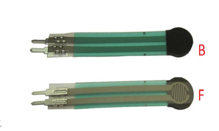
A FORCE sensor is a transducer which changes its resistance when pressure is applied on surface. FORCE sensor is available in different sizes and shapes.
We are going to use one of the cheaper versions because we don’t need much of accuracy here. FSR400 is one of the cheapest force sensors in the market. The picture of FSR400 is shown in below figure.
Now it is important to note that the FSR 400 is sensitive along the length, the force or weight should be concentrated on the maze on the middle of eye of sensor, as shown in figure.
If the force is applied at wrong times the device could damage permanently.
Another important thing to know that, the sensor can drive currents of high range. So keep in mind the driving currents while installing. Also the sensor has a limit on force that is 10Newtons. So we can apply only 1Kg of weight. If weights higher than 1Kg applied the sensor might show some deviations. If it’s increased more than 3Kg. the sensor might damage permanently.
As told earlier this sensor is used to sense the changes in pressure. So when the weight is applied on top of FORCE sensor, the resistance is changed drastically. The resistance of FS400 over weight is shown in below graph:
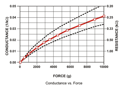
As shown in above figure, the resistance between the two contacts of sensor decreases with weight or the conductance between two contacts of sensor increases.
The resistance of a pure conductor is given by:
![]()
Where,
p- Resistivity of conductor
l= Length of conductor
A= Area of conductor.
Now consider a conductor with resistance “R”, if some pressure is applied on top of conductor, the area on conductor decreases and the length of conductor increases as a result of pressure. So by formula the resistance of conductor should increase, as the resistance R is inversely proportional to area and also directly proportional to length l.
So with this for a conductor under pressure or weight the resistance of conductor increases. But this change is small compared to overall resistance. For a considerable change many conductors are stacked together.
This is what happens inside the Force Sensors shown in above figure. On looking closely one can sees many lines inside the sensor. Each of these lines represents a conductor. Sensitivity of sensor is in conductor numbers.
But in this case the resistance will be decreasing with pressure because the material used here is not a pure conductor. The FSR here are robust polymer thick film (PTF) devices. So these are not pure conductor material devices. These are made up of a material, that exhibit a decrease in resistance with increase in force applied to the surface of the sensor.
This material shows characteristics as shown in graph of FSR.
This change in resistance can do no good unless we can read them. The controller at hand can only read the chances in voltage and nothing less, for this we are going to use voltage divider circuit, with that we can derive the resistance change as voltage change.
Voltage divider is a resistive circuit and is shown in figure. In this resistive network we have one constant resistance and other variable resistance. As shown in figure, R1 here is a constant resistance and R2 is FORCE sensor which acts as a resistance.
The midpoint of branch is taken to measurement. With R2 change, we have change at Vout. So with this we have a voltage which changes with weight.
Now important thing to note here is, the input taken by the controller for ADC conversion is as low as 50µAmp. This loading effect of resistance based voltage divider is important as the current drawn from Vout of voltage divider increases the error percentage increases, for now we need not worry about loading effect.
Now when the force is applied on the FORCE SENSOR, the voltage at divider end changes this pin as connected to ADC channel of UNO, we will get a different digital value from ADC of UNO, whenever force on sensor changes.
This ADC digital value is matched to the duty ratio of PWM signal, so we have the SERVO position control in relation to force applied on sensor.
Components
Hardware: UNO, power supply (5v), 1000uF capacitor, 100nF capacitor (3 pieces), 100KΩ resistor, SERVO MOTOR (SG 90), 220Ω resistor, FSR400 force sensor.
Software: Atmel studio 6.2 or aurdino nightly.
Circuit Diagram and Working Explanation
The circuit diagram for servo motor control by force sensor is shown in below figure.
")
The voltage across sensor is not completely linear; it will be a noisy one. To filter out the noise a capacitors are placed across each resistor in the divider circuit as shown in figure.
Here we are going to take the voltage provided by the divider (voltage which represents weight linearly) and feed it into one of ADC channels of Arduino Uno. After conversion we are going to take that digital value (representing weight) and relate it to PWM value and provide this PWM signal to SERVO motor.
So with weight we have a PWM value which changes its duty ratio depending on digital value. Higher the digital value higher the duty ratio of PWM. So with higher duty ratio PWM signal, the servo shaft should reach the far right or far left as per the figure provided in the introduction.
If the weight is lower, we will have lower PWM duty ratio and as per the figure in introduction the servo should the reach the far right.
With this we have a SERVO position control by WEIGHT or FORCE.
For this to happened we need to establish few instructions in program and we will talk about them in detail below.
ARDUINO has six ADC channels, as show in figure. In those any one or all of them can be used as inputs for analog voltage. The UNO ADC is of 10 bit resolution (so the integer values from (0-(2^10) 1023)).This means that it will map input voltages between 0 and 5 volts into integer values between 0 and 1023. So for every (5/1024= 4.9mV) per unit.
Here we are going to use A0 of UNO. We need to know a few things.
|
First of all the Arduino Uno ADC channels has a default reference value of 5V. This means we can give a maximum input voltage of 5V for ADC conversion at any input channel. Since some sensors provide voltages from 0-2.5V, with a 5V reference we get lesser accuracy, so we have a instruction that enables us to change this reference value. So for changing the reference value we have (“analogReference();”) For now we leave it as.
As default we get the maximum board ADC resolution which is 10bits, this resolution can be changed by using instruction (“analogReadResolution(bits);”). This resolution change can come in handy for some cases. For now we leave it as.
Now if the above conditions are set to default, the we can read value from ADC of channel ‘0’ by directly calling function “analogRead(pin);”, here “pin” represents pin where we connected analog signal, in this case it would be “A0”. The value from ADC can be taken into an integer as “int SENSORVALUE = analogRead(A0); ”, by this instruction the value after ADC gets stored in the integer “SENSORVALUE”.
The PWM of UNO can achieved at any of pins symbolized as “ ~ ” on the PCB board. There are six PWM channels in UNO. We are going to use PIN3 for our purpose.
| analogWrite(3,VALUE); |
From above condition we can directly get the PWM signal at the corresponding pin. The first parameter in brackets is for choosing the pin number of PWM signal. Second parameter is for writing duty ratio.
The PWM value of Arduino Uno can be changed from 0 to 255. With “0” as lowest to “255” as highest. With 255 as duty ratio we will get 5V at PIN3. If the duty ratio is given as 125 we will get 2.5V at PIN3.
Now let’s talk about the servo motor control, the Arduino Uno has a feature which enables us to control the servo position by just giving the degree value. Say if we want the servo to be at 30, we can directly represent the value in the program. The SERVO header file takes care of all the duty ratio calculations internally. You can learn more about servo motor control with arduino here.
Now the sg90 can move from 0-180 degrees, we have ADC result 0-1024.
So ADC is approximately six times the SERVO POSITION. So by divided the ADC result by 6 we will get the approximate SERVO hand position. Hence we have a PWM signal whose duty ratio changes linearly with WEIGHT or FORCE. This being given to servo motor, we can control the servo motor by force sensor.
Complete Project Code
#include <Servo.h> //header for controller servo
Servo servo; //keeping name of servo SERVO itself
int sensorvalue =0;
void setup()
{
            pinMode(A0,INPUT); //force sensor value input
            pinMode(3,OUTPUT); //PWM output to servo
            servo.attach(3); //telling where signal pin of servo attached(must be a PWM pin)
}

void loop()
{
            sensorvalue = analogRead(A0); //read analog value from sensor
            servo.write(sensorvalue/6); //set servo position based on ADC result
}

How do I make the servo motor rotate at a specific weight say 15kg using a load cell of 20 kg.