

In this project we will be developing a fun circuit using Force sensor and Arduino Uno. This circuit generates sound linearly related to force applied on the sensor. For that we are going to interface FORCE sensor with Arduino Uno. In UNO, we are going use 8 bit ADC (Analog to Digital Conversion) feature to do the job.
Force Sensor or Force Sensitive Resistor
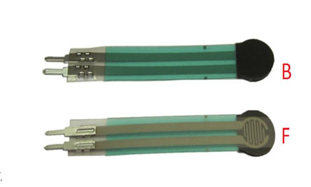
A FORCE sensor is a transducer which changes its resistance when pressure is applied on surface. FORCE sensor is available in different sizes and shapes. We are going to use one of the cheaper versions because we don’t need much of accuracy here. FSR400 is one of the cheapest force sensors in the market. The picture of FSR400 is shown in below figure. They are also called Force-sensitive resistor or FSR as its resistance changes according to the force or pressure applied to it. When pressure is applied to this force sensing resistor its resistance decreases that is, the resistance is inversely proportional to the force applied. So when no pressure is applied on it, the resistance of FSR will be very high.
Now it is important to note that the FSR 400 is sensitive along the length, the force or weight should be concentrated on the maze on the middle of eye of sensor, as shown in figure. If the force is applied at wrong times the device could damage permanently.
Another important thing to know that, the sensor can drive currents of high range. So keep in mind the driving currents while installing. Also the sensor has a limit on force that is 10 Newtons. So we can apply only 1Kg of weight. If weights higher than 1Kg applied the sensor might show some deviations. If it’s increased more than 3Kg. the sensor might damage permanently.
As told earlier this sensor is used to sense the changes in pressure. So when the weight is applied on top of FORCE sensor, the resistance is changed drastically. The resistance of FS400 over weight is shown in below graph,
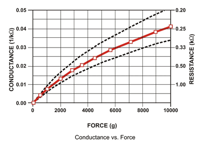
As shown in above figure, the resistance between the two contacts of sensor decreases with weight or the conductance between two contacts of sensor increases. The resistance of a pure conductor is given by:
![]()
Where,
p- Resistivity of conductor
l= Length of conductor
A= Area of conductor.
Now consider a conductor with resistance “R”, if some pressure is applied on top of conductor, the area on conductor decreases and the length of conductor increases as a result of pressure. So by formula the resistance of conductor should increase, as the resistance R is inversely proportional to area and also directly proportional to length l.
So with this for a conductor under pressure or weight the resistance of conductor increases. But this change is small compared to overall resistance. For a considerable change many conductors are stacked together. This is what happens inside the Force Sensors shown in above figure. On looking closely one can sees many lines inside the sensor. Each of these lines represents a conductor. Sensitivity of sensor is in conductor numbers.
But in this case the resistance will be decreasing with pressure because the material used here is not a pure conductor. The FSR here are robust polymer thick film (PTF) devices. So these are not pure conductor material devices. These are made up of a material, that exhibit a decrease in resistance with increase in force applied to the surface of the sensor. This material shows characteristics as shown in graph of FSR.
This change in resistance can do no good unless we can read them. The controller at hand can only read the chances in voltage and nothing less, for this we are going to use voltage divider circuit, with that we can derive the resistance change as voltage change.
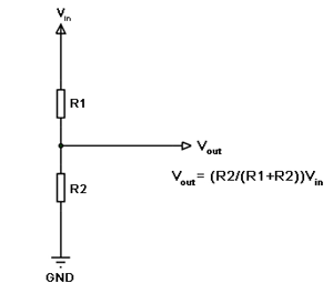
Voltage divider is a resistive circuit and is shown in figure. In this resistive network we have one constant resistance and other variable resistance. As shown in figure, R1 here is a constant resistance and R2 is FORCE sensor which acts as a resistance. The midpoint of branch is taken to measurement. With R2 change, we have change at Vout. So with this we have a voltage change with weight.
Now important thing to note here is, the input taken by the controller for ADC conversion is as low as 50µAmp. This loading effect of resistance based voltage divider is important as the current drawn from Vout of voltage divider increases the error percentage increases, for now we need not worry about loading effect.
How to check a FSR Sensor
The force sensing resistor can be tested using a multimeter. Connect the two pins of FSR sensor to the multimeter without applying any force and check the resistance value, it will be very high. Then apply some force to its surface and see the decrement in resistance value.
Applications of FSR Sensor
Force-sensing resistors are mainly used to create pressure-sensing "buttons". They are used in a variety of fields such as car occupancy sensors, resistive touch-pads, robotic fingertips, artificial limbs, keypads, Foot pronation systems, musical instruments, Embedded Electronics, Testing and Measurement Equipment, OEM Development Kit and portable electronics, sports. They are also used in Augmented Reality systems as well as to enhance mobile interaction.
Components Required
Hardware: Arduino Uno, Power supply (5v), 1000 uF Capacitor, 100nF capacitor (3 pieces), 100KΩ resistor, Buzzer, 220Ω resistor, FSR400 Force sensor.
SOFTWARE: Atmel studio 6.2 or Aurdino nightly
Circuit Diagram and Working Explanation
The circuit connection for interfacing Force sensing Resistor with Arduino is shown in below diagram.

The voltage across sensor is not completely linear; it will be a noisy one. To filter out the noise a capacitors are placed across each resistor in the divider circuit as shown in figure.
Here we are going to take the voltage provided by the divider (voltage which represents weight linearly) and feed it into one of ADC channels of UNO. After conversion we are going to take that digital value (representing weight) and relate it to PWM value for driving the buzzer.
So with weight we have a PWM value which changes its duty ratio depending on digital value. Higher the digital value higher the duty ratio of PWM so higher the noise generated by buzzer. So we related weight to sound.
Before going any further lets talk about ADC of Arduino Uno. ARDUINO has six ADC channels, as show in figure. In those any one or all of them can be used as inputs for analog voltage. The UNO ADC is of 10 bit resolution (so the integer values from (0-(2^10) 1023)).This means that it will map input voltages between 0 and 5 volts into integer values between 0 and 1023. So for every (5/1024= 4.9mV) per unit.
Here we are going to use A0 of UNO.
We need to know few things.
|
First of all the UNO ADC channels has a default reference value of 5V. This means we can give a maximum input voltage of 5V for ADC conversion at any input channel. Since some sensors provide voltages from 0-2.5V, with a 5V reference we get lesser accuracy, so we have a instruction that enables us to change this reference value. So for changing the reference value we have (“analogReference();”) For now we leave it as.
As default we get the maximum board ADC resolution which is 10bits, this resolution can be changed by using instruction (“analogReadResolution(bits);”). This resolution change can come in handy for some cases. For now we leave it as.
Now if the above conditions are set to default, the we can read value from ADC of channel ‘0’ by directly calling function “analogRead(pin);”, here “pin” represents pin where we connected analog signal, in this case it would be “A0”. The value from ADC can be taken into an integer as “int SENSORVALUE = analogRead(A0); ”, by this instruction the value after ADC gets stored in the integer “SENSORVALUE”.
The PWM of Arduino Uno can achieved at any of pins symbolized as “ ~ ” on the PCB board. There are six PWM channels in UNO. We are going to use PIN3 for our purpose.
analogWrite(3,VALUE); |
From above condition we can directly get the PWM signal at the corresponding pin. The first parameter in brackets is for choosing the pin number of PWM signal. Second parameter is for writing duty ratio.
The PWM value of UNO can be changed from 0 to 255. With “0” as lowest to “255” as highest. With 255 as duty ratio we will get 5V at PIN3. If the duty ratio is given as 125 we will get 2.5V at PIN3.
Now we have 0-1024 value as ADC output and 0-255 as PWM duty ratio. So ADC is approximately four times the PWM ratio. So by divided the ADC result by 4 we will get the approximate duty ratio.
With that we will have a PWM signal whose duty ratio changes linearly with weight. This being given to buzzer, we have sound generator depending on weight.
Complete Project Code
int sensorvalue =0; // Interger for storing ADC result
void setup()
{
                pinMode(A0,INPUT); // ADC result input
                pinMode(3,OUTPUT); // PWM signal output pin
}
void loop()
{
                sensorvalue = analogRead(A0); // Read analog value and store it in integer
                analogWrite(3,sensorvalue/4); // PWM duty ratio given
}
