

For any project to come alive, we need to use sensors. Sensors acts as the eyes and ears for all embedded application, it helps the digital Microcontroller to understand what is actually happening in this real Analog world. In this tutorial we will be learning how to Interface Ultrasonic Sensor HC-SR04 with PIC microcontroller.
The HC-SR04 is an ultrasonic sensor which can be used to measure distance anywhere between 2cm to 450cm (theoretically). This sensor has proved itself worthy by fitting into many projects which involves obstacles detection, distance measuring, environment mapping etc. At the end of this article you will learn how this sensor works and how to interface it with PIC16F877A microcontroller to measure the distance and display it on the LCD screen. Sounds interesting right!! So let’s get started...
Materials Required:
- PIC16F877A MCU with programming set-up
- LCD 16*2 display
- Ultrasonic sensor (HC-SR04)
- Connecting wires
How does an Ultrasonic Sensor work?
Before we get any further, we should know how an Ultrasonic sensor works so that we can understand this tutorial much better. The ultrasonic sensor used in this project is shown below.
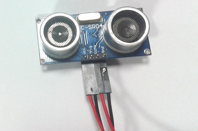
As you can see it has two circular eyes like projections and four pins coming out of it. The two eye like projections are the Ultrasonic wave (hereafter referred as US wave) Transmitter and receiver. The transmitter emits an US wave at a frequency of 40Hz, this wave travels through the air and gets reflected back when it senses an object. The returning waves are observed by the receiver. Now we know the time taken for this wave to get reflected and come back and the speed of the US wave is also universal (3400cm/s). Using this information and the below high school formulae we can calculate the distance covered.
Distance = Speed × Time
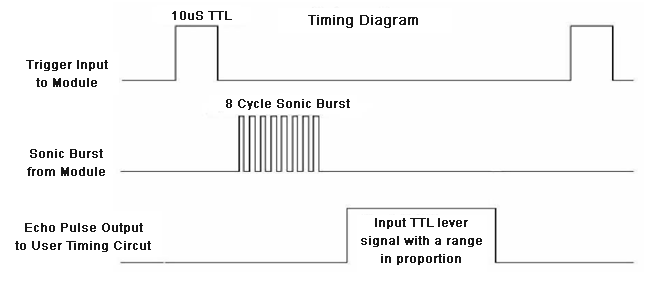
Now that we know how an US sensor works, let us how it can be interfaced with any MCU/CPU using the four pins. These four pins are Vcc, Trigger, Echo and Ground respectively. The module works on +5V and hence the Vcc and ground pin is used to power the module. The other two pins are the I/O pins using which we communicate to our MCU. The trigger pin should be declared as an output pin and made high for a 10uS, this will transmit the US wave into the air as 8 cycle sonic burst. Once the wave is observed the Echo pin will go high for the exact interval of time which was taken by the US wave to return back to the sensor module. Hence this Echo pin will be declared as input and a timer will be used to measure how long the pin was high. This could further be understood by the timing diagram below.
Hope you have arrived at a tentative way to interface this sensor with PIC. We will be using the Timer module and LCD module in this tutorial and I assume you are familiar with both, if not please fall back to the respective tutorial below since I will be skipping most of the information related to it.
Circuit Diagram:
The complete circuit diagram for interfacing Ultrasonic Sensor with PIC16F877A is shown below:

As shown, the circuit involves nothing more than a LCD display and the Ultrasonic sensor itself. The US sensor can be powered by +5V and hence it is directly powered by the 7805 voltage regulator. The sensor has one output pin (Trigger pin) which is connected to pin 34 (RB1) and the input pin (Echo pin) is connected to pin 35 (RB2). The complete pin connection is illustrated in the table below.
|
S.No: |
PIC Pin Number |
Pin Name |
Connected to |
|
1 |
21 |
RD2 |
RS of LCD |
|
2 |
22 |
RD3 |
E of LCD |
|
3 |
27 |
RD4 |
D4 of LCD |
|
4 |
28 |
RD5 |
D5 of LCD |
|
5 |
29 |
RD6 |
D6 of LCD |
|
6 |
30 |
RD7 |
D7 of LCD |
|
7 |
34 |
RB1 |
Trigger of US |
|
8 |
35 |
RB2 |
Echo of US |
Programming your PIC Microcontroller:
The complete program for this tutorial is given at the end of this page, further below I have explained the code into small meaning full chunks for you to understand. As said earlier the program involves the concept of LCD interfacing and Timer which will not explained in details in this tutorial since we have already covered them in the previous tutorials.
Inside, the main function we start with initializing the IO pins and other registers as usual. We define the IO pins for LCD and US sensor and also initiate the Timer 1 register by setting it to work on 1:4 pre-scalar and to use internal clock (Fosc/4)
  TRISD = 0x00; //PORTD declared as output for interfacing LCD
    TRISB0 = 1;        //Define the RB0 pin as input to use as interrupt pin
    TRISB1 = 0; //Trigger pin of US sensor is sent as output pin
    TRISB2 = 1; //Echo pin of US sensor is set as input pin
    TRISB3 = 0; //RB3 is output pin for LED
    T1CON=0x20; //4 pres-scalar and internal clock
The Timer 1 is a 16-bit timer used in PIC16F877A, the T1CON register control the parameters of the timer module and the result will be stored in TMR1H and TMR1L since it a 16-bit result the first 8 will be stored in TMR1H and the next 8 in TMR1L. This timer can be turned on or off using TMR1ON=0 and TMR1ON=1 respectively.
Now, the timer is ready to use, but we have to send the US waves out of the sensor, to do this we have to keep the Trigger pin high for 10uS, this is done by the following code.
        Trigger = 1;
        __delay_us(10);
        Trigger = 0;
As shown in timing diagram above, the Echo pin will stay low till the wave return back and will then go high and stay high for the exact time taken for the waves to return back. This time has to be measured by the Timer 1 module, which can be done by the below line
        while (Echo==0);
            TMR1ON = 1;
        while (Echo==1);
            TMR1ON = 0;
Once the time is measured the resulting value will be saved in the registers TMR1H and TMR1L, these registers have to be clubbed to gather to get the 16-bit value. This is done by using the line below
time_taken = (TMR1L | (TMR1H<<8));
This time_taken will be in form bytes, to get the actual time value we have to use the below formula.
Time = (16-bit register value) * (1/Internal Clock) * (Pre-scale)
Internal Clock = Fosc/4

Where in our case,
Fosc = 20000000Mhz and Pre-scale = 4

Hence the value of Internal Clock will be 5000000Mhz and the value of time will be

Time = (16-bit register value) * (1/5000000) * (4)
          = (16-bit register value) * (4/5000000)
          = (16-bit register value) * 0.0000008 seconds (OR)
Time = (16-bit register value) * 0.8 micro seconds
In our program the value of the 16-bit register is stored in the variable time_taken and hence the below line is used to calculate the time_taken in micro seconds
time_taken = time_taken * 0.8;
Next we have to find how to calculate the distance. As we know distance = speed * time. But here the result should be divided by 2 since the wave is covering both the transmitting distance and receiving distance. The speed of us wave (sound) is 34000cm/s.
Distance = (Speed*Time)/2
                = (34000 * (16-bit register value) * 0.0000008) /2
Distance = (0.0272 * 16-bit register value)/2
So the distance can be calculated in centimeters like below:
distance= (0.0272*time_taken)/2;
After calculating the value of distance and time taken we simply have to display them on the LCD screen.
Measuring distance using PIC and Ultrasonic Sensor:
After making the connections and uploading the code, your experimental set-up should look something like this shown in the below picture.
The PIC Perf board, showing in this picture, was made for our PIC tutorial series, in which we learnt how to use PIC microcontroller. You might want to go back to those PIC Microcontroller tutorials using MPLABX and XC8 if you do not know how to burn a program using Pickit 3, since I will be skipping all those basic information.
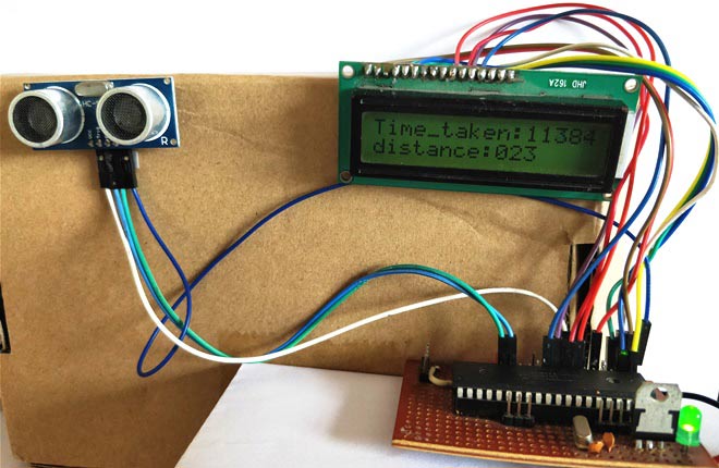
Now place an object before the sensor and it should display how far the object is from the sensor. You can also notice the time taken being displayed in micro seconds for the wave to transmit and return back.
You can move the object at your preferred distance and check the value that is displayed on the LCD. I was able to measure distance from 2cm to 350cm with an accuracy of 0.5cm. This is quite a satisfactory result! Hope you enjoyed the tutorial and learnt how to make something on your own. If you have any doubts drop them in the comment section below or use the forums.
Also check interfacing of Ultrasonic sensor with other microcontrollers:
Complete Project Code
/*
Interfacing Ultrasonic sensor with PIC16F877A
 * Code by: B.Aswinth Raj
 * Dated: 19-07-2017
 * More details at: www.CircuitDigest.com
 */
#define _XTAL_FREQ 20000000
#define RS RD2
#define EN RD3
#define D4 RD4
#define D5 RD5
#define D6 RD6
#define D7 RD7
#define Trigger RB1 //34 is Trigger
#define Echo RB2//35 is Echo
#include <xc.h>
#pragma config FOSC = HS        // Oscillator Selection bits (HS oscillator)
#pragma config WDTE = OFF       // Watchdog Timer Enable bit (WDT disabled)
#pragma config PWRTE = ON       // Power-up Timer Enable bit (PWRT enabled)
#pragma config BOREN = ON       // Brown-out Reset Enable bit (BOR enabled)
#pragma config LVP = OFF        // Low-Voltage (Single-Supply) In-Circuit Serial Programming Enable bit (RB3 is digital I/O, HV on MCLR must be used for programming)
#pragma config CPD = OFF        // Data EEPROM Memory Code Protection bit (Data EEPROM code protection off)
#pragma config WRT = OFF        // Flash Program Memory Write Enable bits (Write protection off; all program memory may be written to by EECON control)
#pragma config CP = OFF         // Flash Program Memory Code Protection bit (Code protection off)
//LCD Functions Developed by Circuit Digest.
void Lcd_SetBit(char data_bit) //Based on the Hex value Set the Bits of the Data Lines
{
if(data_bit& 1)
D4 = 1;
else
D4 = 0;
if(data_bit& 2)
D5 = 1;
else
D5 = 0;
if(data_bit& 4)
D6 = 1;
else
D6 = 0;
if(data_bit& 8)
D7 = 1;
else
D7 = 0;
}
void Lcd_Cmd(char a)
{
RS = 0;
Lcd_SetBit(a); //Incoming Hex value
EN  = 1;
        __delay_ms(4);
        EN  = 0;
}
void Lcd_Clear()
{
Lcd_Cmd(0); //Clear the LCD
Lcd_Cmd(1); //Move the curser to first position
}
void Lcd_Set_Cursor(char a, char b)
{
char temp,z,y;
if(a== 1)
{
 temp = 0x80 + b - 1; //80H is used to move the curser
z = temp>>4; //Lower 8-bits
y = temp & 0x0F; //Upper 8-bits
Lcd_Cmd(z); //Set Row
Lcd_Cmd(y); //Set Column
}
else if(a== 2)
{
temp = 0xC0 + b - 1;
z = temp>>4; //Lower 8-bits
y = temp & 0x0F; //Upper 8-bits
Lcd_Cmd(z); //Set Row
Lcd_Cmd(y); //Set Column
}
}
void Lcd_Start()
{
  Lcd_SetBit(0x00);
  for(int i=1065244; i<=0; i--)  NOP();
  Lcd_Cmd(0x03);
__delay_ms(5);
  Lcd_Cmd(0x03);
__delay_ms(11);
  Lcd_Cmd(0x03);
  Lcd_Cmd(0x02); //02H is used for Return home -> Clears the RAM and initializes the LCD
  Lcd_Cmd(0x02); //02H is used for Return home -> Clears the RAM and initializes the LCD
  Lcd_Cmd(0x08); //Select Row 1
  Lcd_Cmd(0x00); //Clear Row 1 Display
  Lcd_Cmd(0x0C); //Select Row 2
  Lcd_Cmd(0x00); //Clear Row 2 Display
  Lcd_Cmd(0x06);
}
void Lcd_Print_Char(char data)  //Send 8-bits through 4-bit mode
{
   char Lower_Nibble,Upper_Nibble;
   Lower_Nibble = data&0x0F;
   Upper_Nibble = data&0xF0;
   RS = 1;             // => RS = 1
   Lcd_SetBit(Upper_Nibble>>4);             //Send upper half by shifting by 4
   EN = 1;
   for(int i=2130483; i<=0; i--)  NOP();
   EN = 0;
   Lcd_SetBit(Lower_Nibble); //Send Lower half
   EN = 1;
   for(int i=2130483; i<=0; i--)  NOP();
   EN = 0;
}
void Lcd_Print_String(char *a)
{
int i;
for(i=0;a[i]!='\0';i++)
  Lcd_Print_Char(a[i]);  //Split the string using pointers and call the Char function
}
/*****End of LCD Functions*****/
int time_taken;
int distance;
char t1,t2,t3,t4,t5;
char d1,d2,d3;
int main()
{
    TRISD = 0x00; //PORTD declared as output for interfacing LCD
    TRISB0 = 1;        //DEfine the RB0 pin as input to use as interrupt pin
    TRISB1 = 0; //Trigger pin of US sensor is sent as output pin
    TRISB2 = 1; //Echo pin of US sensor is set as input pin
    TRISB3 = 0; //RB3 is output pin for LED
    T1CON=0x20;
    Lcd_Start();
    Lcd_Set_Cursor(1,1);
    Lcd_Print_String("Ultrasonic sensor");
    Lcd_Set_Cursor(2,1);
    Lcd_Print_String("with PIC16F877A");
    __delay_ms(2000);
    Lcd_Clear();
    while(1)
    {
        TMR1H =0; TMR1L =0; //clear the timer bits
        Trigger = 1;
        __delay_us(10);
        Trigger = 0;
        while (Echo==0);
            TMR1ON = 1;
        while (Echo==1);
            TMR1ON = 0;
        time_taken = (TMR1L | (TMR1H<<8));
        distance= (0.0272*time_taken)/2;
        time_taken = time_taken * 0.8;
        t1 = (time_taken/1000)%10;
        t2 = (time_taken/1000)%10;
        t3 = (time_taken/100)%10;
        t4 = (time_taken/10)%10;
        t5 = (time_taken/1)%10;
        d1 = (distance/100)%10;
        d2 = (distance/10)%10;
        d3 = (distance/1)%10;
        Lcd_Set_Cursor(1,1);
        Lcd_Print_String("Time_taken:");
        Lcd_Print_Char(t1+'0');
        Lcd_Print_Char(t2+'0');
        Lcd_Print_Char(t3+'0');
        Lcd_Print_Char(t4+'0');
        Lcd_Print_Char(t5+'0');
         Lcd_Set_Cursor(2,1);
        Lcd_Print_String("distance:");
        Lcd_Print_Char(d1+'0');
        Lcd_Print_Char(d2+'0');
        Lcd_Print_Char(d3+'0');
    }
    return 0;
}
Comments
share
hello. can you share your work? hi guys; tried this code on the PIC16F877A and it works well. I'm using it in an application where I need to monitor a liquid level. Every time the liquid level decreases (increase in distance), another routine must be triggered (i.e. send sms to the user).
Could somebody please tell me how I can go about doing this. I know it sounds easy but I just can't seem to do it. I'm using MPLABX, XC8. thanks in advance
xc.h not worked
Hi guys, when I compile the code in mikroC pro, it shows an error that is "17 304 error: Can't open include file "xc.h" #include <xc.h> 1 error in preprocessor. C:\Users\Mushfiq Fuad\Desktop\New folder\MyProject.c". What should I do now?
hi please tell me how for
hi please tell me how for loop use in this programe
From your question, I could
From your question, I could tell you are a very bigener with programming. So I would recommend you to start from the very first tutorial of the PIC series which can be found in link below.
HOW USE THIS RANGES 1065244
HOW USE THIS RANGES 1065244 AND 2130483
simplest code of distance measure using 8 bit pin of lcd
//in above program use unnecessary like loops and show wrong value of time as you show in above lcd pic.
/////////////////////////////////////simple code////////////////////////////////////////////////////////////////////////////
/*
* File: LCD8bit.c
* Author: HP
*
* Created on December 6, 2017, 8:35 AM
*/
#define _XTAL_FREQ 20000000
#include <xc.h>
#include<stdlib.h>
#include<stdio.h>
__PROG_CONFIG(1,0x3F32);
//***********************************************************
#define LCD_DATA_PORT PORTB
#define LCD_DATA_PORT_DIR TRISB
#define RS_PIN PORTCbits.RC0
#define RS_PIN_DIR TRISCbits.TRISC0
#define RW_PIN PORTCbits.RC1
#define RW_PIN_DIR TRISCbits.TRISC1
#define ENABLE_PIN PORTCbits.RC2
#define ENABLE_PIN_DIR TRISCbits.TRISC2
//************************************************************
#define Trigger RD1 // Trigger pin
#define Echo RD2// Echo pin
//Function init************************************************************
void Lcd_Clear();
void LCD_Init(void);
void Toggle_Enable(void);
void LCD_Send_Data(unsigned char Data);
void LCD_Send_Command(unsigned char Command);
void Lcd_Set_Cursor(unsigned char a,unsigned char b);
//************************************************************
void Toggle_Enable(void)
{
ENABLE_PIN=1;
__delay_us(10);
ENABLE_PIN=0;
}
//************************************************************
void LCD_Send_Command(unsigned char Command)
{
RS_PIN=0;
RW_PIN=0;
LCD_DATA_PORT=Command;
Toggle_Enable();
__delay_ms(5);
}
//************************************************************
void Lcd_Set_Cursor(unsigned char a,unsigned char b)
{
char temp;
if(a==1)
{
temp = 0x80 + b - 1;
LCD_Send_Command(temp);
}
else
{
temp = 0xC0 + b - 1;
LCD_Send_Command(temp); //Set Column
}
}
//************************************************************
void LCD_Init(void)
{
//Wait for 100 mSec
__delay_ms(100);
//*********************************************************
LCD_Send_Command(0x30);
//*********************************************************
__delay_ms(10);
//*********************************************************
LCD_Send_Command(0x30);
//*********************************************************
__delay_ms(10);
//*********************************************************
RS_PIN=0;
RW_PIN=0;
LCD_DATA_PORT=0x30;
Toggle_Enable();
//font=0,and n=1********************************************
__delay_ms(100);
RS_PIN=0;
RW_PIN=0;
LCD_DATA_PORT=0x38;
Toggle_Enable();
__delay_ms(50);
//display 0ff**********************************************
RS_PIN=0;
RW_PIN=0;
LCD_DATA_PORT=0x08;
Toggle_Enable();
__delay_ms(50);
//********************************************************
RS_PIN=0;
RW_PIN=0;
LCD_DATA_PORT=0x0C;
Toggle_Enable();
__delay_ms(50);
//display clear********************************************
RS_PIN=0;
RW_PIN=0;
LCD_DATA_PORT=0x01;
Toggle_Enable();
__delay_ms(50); //delay so that the command can be
//executed by LCD Controller
//entry mode set*******************************************
RS_PIN=0;
RW_PIN=0;
LCD_DATA_PORT=0x06;
Toggle_Enable();
__delay_ms(50); //delay so that the command can be
//executed by LCD Controller
}
//************************************************************
void LCD_Send_Data(unsigned char Data)
{
RS_PIN=1;
RW_PIN=0;
LCD_DATA_PORT=Data;
Toggle_Enable();
__delay_ms(50);
}
//init of variables************************************************************
unsigned int time_taken=0;
unsigned int distance;
unsigned int t0=0,t1=0,t2=0,t3=0,t4=0,t5=0,t6=0,t7=0;
unsigned int d1,d2,d3;
void main(void)
{
TRISD1 = 0; //Trigger pin of US sensor is sent as output pin
TRISD2 = 1; //Echo pin of US sensor is set as input pin
TRISC =0X00;
PORTC=0X00;
T1CON=0x20;
LCD_Init();
//Make the LCD data port an output
LCD_DATA_PORT_DIR=0x00;
//Make the RS pin an output
RS_PIN_DIR=0;
//Make the RW pin an output
RW_PIN_DIR=0;
//Make the Enable pin an output
ENABLE_PIN_DIR=0;
unsigned char i;
LCD_Init();
Lcd_Set_Cursor(1,1);
LCD_Send_Data('S');
LCD_Send_Data('H');
LCD_Send_Data('A');
LCD_Send_Data('R');
LCD_Send_Data('Y');
LCD_Send_Data(' ');
LCD_Send_Data('H');
LCD_Send_Data('M');
LCD_Send_Data('Z');
LCD_Send_Data('A');
LCD_Send_Data(' ');
LCD_Send_Data('R');
LCD_Send_Data('O');
LCD_Send_Data('M');
LCD_Send_Data('A');
LCD_Send_Data('N');
__delay_ms(2000);
Lcd_Set_Cursor(2,1);
LCD_Send_Data('D');
LCD_Send_Data('I');
LCD_Send_Data('S');
LCD_Send_Data('T');
LCD_Send_Data('A');
LCD_Send_Data('N');
LCD_Send_Data('C');
LCD_Send_Data('_');
LCD_Send_Data('_');
LCD_Send_Data('M');
LCD_Send_Data('E');
LCD_Send_Data('A');
LCD_Send_Data('S');
LCD_Send_Data('U');
LCD_Send_Data('R');
LCD_Send_Data('E');
__delay_ms(2000);
LCD_Send_Command(0X01);
while(1)
{
TMR1H =0; TMR1L =0; //clear the timer bits
Trigger = 1;
__delay_us(10);
Trigger = 0;
while (Echo==0);
TMR1ON = 1;
while (Echo==1);
TMR1ON = 0;
time_taken = (TMR1L | (TMR1H<<8));
distance= (0.0272*time_taken)/2;
time_taken = time_taken * 0.8;
t0=time_taken/10000;
t1=time_taken%10000;
t2=t1/1000;
t3=t1%1000;
t4=t3/100;
t5=t3%100;
t6=t5/10;
t7=t5%10;
d1 = (distance/100)%10;
d2 = (distance/10)%10;
d3 = (distance/1)%10;
Lcd_Set_Cursor(1,1);
LCD_Send_Data('T');
LCD_Send_Data('I');
LCD_Send_Data('M');
LCD_Send_Data('E');
LCD_Send_Data(':');
LCD_Send_Data(t0+'0');
LCD_Send_Data(t2+'0');
LCD_Send_Data(t4+'0');
LCD_Send_Data(t6+'0');
LCD_Send_Data(t7+'0');
LCD_Send_Data(' ');
LCD_Send_Data('u');
LCD_Send_Data('s');
Lcd_Set_Cursor(2,1);
LCD_Send_Data('D');
LCD_Send_Data('I');
LCD_Send_Data('S');
LCD_Send_Data('T');
LCD_Send_Data('A');
LCD_Send_Data('N');
LCD_Send_Data('C');
LCD_Send_Data('E');
LCD_Send_Data(':');
LCD_Send_Data(d1+'0');
LCD_Send_Data(d2+'0');
LCD_Send_Data(d3+'0');
LCD_Send_Data(' ');
LCD_Send_Data('c');
LCD_Send_Data('m');
__delay_ms(1000);
}
return;
}
Regarding connection details
sir,
Here you used to see the output in LCD display...But I want to see the same result in the system using any software like MPLAB? How can I sir?
And I hope that I will get your guidance.
please i need the code file
please send the code to my email
and thank you very much please help me i need the project
implementing in mikroc
Hi! how can i implement the code in mikroc and can i use a simple 5v battery instead of voltage reg for US. also how should i power the lcd?
elaborate briefly.
reply asap
understanding
Hello sir,
I am a final year student studying Electrical and Electronic Engineering, I am using a part of this code to display information on a LCD from a PIC. I am having trouble understanding this part of the code below, would you be able to elaborate?
(distance/100)%10;
(distance/10)%10;
(distance/1)%10;
(d1+'0');
why does it divide by 100 and then divide by 10%
why does it divide by 100, 10 and 1.
and why do we need a +'0' when printing the characters on LCD?
Thank you for uploading this code, kind regards
Patrick
To split three digit numbers
Say you have the va;ue of distance as 745 and you have to display it on the LCD. In this case you have to send only one char at a time so we have to split 745 into three chars that is 7, 4 and 5. To do that
(distance/100)%10 = 7.45%10 = 7
(distance/10)%10 = 74.5%10 = 4
(distance/1)%10; = 745%10 = 5
Now the LCD not not undertstand char type variable. It understands only ASCII. So we have to add '0' with all the values before sending to LCD. You can check the ASCII table if you have doubt in this
Hi, what microcontroller are
Hi, what microcontroller are you using?
We are using PIC16F877A
We are using PIC16F877A microcontroller here.
I think at this part of the
I think at this part of the code :
t1 = (time_taken/1000)%10;
you should have put 10000 , not 1000

hi guys; tried this code on the PIC16F877A and it works well. I'm using it in an application where I need to monitor a liquid level. Every time the liquid level decreases (increase in distance), another routine must be triggered (i.e. send sms to the user).
Could somebody please tell me how I can go about doing this. I know it sounds easy but I just can't seem to do it. I'm using MPLABX, XC8. thanks in advance