

In this tutorial we learn to Enable UART communication with PIC Microcontroller and how to transfer data to and from your Computer. So far, we have covered all basic modules like ADC, Timers, PWM and also have learnt how to interface LCDs and 7-Segment displays. Now, we will equip our self with a new communication tool called UART which widely used in most of the Microcontroller projects. Check here our complete PIC Microcontroller Tutorials using MPLAB and XC8.
Here we have used PIC16F877A MCU, it has a module called “Addressable Universal Synchronous Asynchronous Receiver and Transmitter” shortly known as USART. USART is a two wire communication system in which the data flow serially. USART is also a full-duplex communication, means you can send and receive data at the same time which can be used to communicate with peripheral devices, such as CRT terminals and personal computers.
The USART can be configured in the following modes:
- Asynchronous (full-duplex)
- Synchronous – Master (half-duplex)
- Synchronous – Slave (half-duplex)
There are also two different modes namely the 8-bit and 9-bit mode, in this tutorial we will configure the USART module to work in Asynchronous mode with 8-bit communication system, since it is the most used type of communication. As it is asynchronous it doesn't need to send clock signal along with the data signals. UART uses two data lines for sending (Tx) and receiving (Rx) data. The ground of both devices should also be made common. This type of communication does not share a common clock hence a common ground is very important for the system to work.
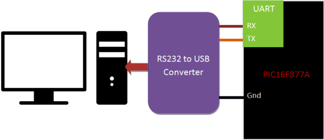
At the end of this tutorial you will be able establish a communication (UART) between your computer and your PIC Microcontroller and toggle an LED on the PIC board from your laptop. The status of the LED will be sent to your laptop from the PIC MCU. We will test the output using Hyper Terminal in computer. Detailed Video is also given at the end of this tutorial.
Requirements:
Hardware:
- PIC16F877A Perf Board
- RS232 to USB converter Module
- Computer
- PICkit 3 Programmer
Software:
- MPLABX
- HyperTerminal
A RS232 to USB converter is required to convert the serial data into computer readable form. There are ways to design your own circuit instead of buying your own module but they are not reliable as they are subjected noise. The one which we are using is shown below
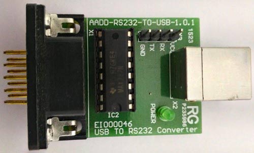
Note: Each RS232 to USB converter would require a special driver to be installed; most of them should get installed automatically as soon as you plug in the device. But, if it doesn’t relax!!! Use the comment section and I will help you out.
Programming PIC Microcontroller for UART Communication:
Like all modules (ADC, Timer, PWM) we should also initialize our USART module of our PIC16F877A MCU and instruct it to work in UART 8-bit communication mode. Let’s define the configuration bits and start with the UART initialization function.
Initializing the UART module of the PIC Microcontroller:
The Tx and Rx pins are physically present at the pins RC6 and RC7. According to datasheet let’s declare TX as output and RX as input.
    //****Setting I/O pins for UART****//
    TRISC6 = 0; // TX Pin set as output
    TRISC7 = 1; // RX Pin set as input
    //________I/O pins set __________//
Now the baud rate has to be set. The baud rate is the rate at which information is transferred in a communication channel. This can be one of the many default values, but in this program we are using 9600 since its the most used baud rate.
    /**Initialize SPBRG register for required
    baud rate and set BRGH for fast baud_rate**/
    SPBRG = ((_XTAL_FREQ/16)/Baud_rate) - 1;
    BRGH  = 1;  // for high baud_rate
    //_________End of baud_rate setting_________//
The value of the baud rate has to be set using the register SPBRG, the value depends on the value of the External crystal frequency, the formulae to calculate the baud rate is shown below:
SPBRG = ( ( _XTAL_FREQ/16 ) / Baud_rate) – 1;
The bit BRGH has to be made high to enable high speed bit rate. According to datasheet (page 13) it is always advantageous to enable it, as it can eliminate errors during communication.
As said earlier we will be working in Asynchronous mode, hence the bit SYNC should be made zero and bit SPEM must be made high to enable serial pins (TRISC6 and TRICSC5)
    //****Enable Asynchronous serial port*******//
    SYNC  = 0;    // Asynchronous
    SPEN  = 1;    // Enable serial port pins
    //_____Asynchronous serial port enabled_______//
In this tutorial we will be both sending and receiving data between MCU and computer hence we have to enable both TXEN and CREN bits.
    //**Lets prepare for transmission & reception**//
    TXEN  = 1;    // enable transmission
    CREN  = 1;    // enable reception
    //__UART module up and ready for transmission and reception__//
The bits TX9 and RX9 have to be made zero so that we operate in 8-bit mode. If there has to be high reliability need to be established then 9-bit mode can be selected.
    //**Select 8-bit mode**//
    TX9   = 0;    // 8-bit reception selected
    RX9   = 0;    // 8-bit reception mode selected
    //__8-bit mode selected__//
With this we complete our initialization setup. Now the Module is configured as UART and is ready for operation.
Transmitting data using UART:
The below function can be used to transmit data through the UART module:
//**Function to send one byte of date to UART**//
void UART_send_char(char bt)
{
    while(!TXIF);  // hold the program till TX buffer is free
    TXREG = bt; //Load the transmitter buffer with the received value
}
//_____________End of function________________//
Once the module is initialized whatever value is loaded into the register TXREG will be transmitted through UART, but transmission might overlap. Hence we should always check for the Transmission Interrupt flag TXIF. Only if this bit is low we can proceed with the next bit for transmission else we should wait for this flag to get low.
However, above function can be used only to send only one byte of data, to send a complete a string the below function should be used
//**Function to convert string to byte**//
void UART_send_string(char* st_pt)
{
    while(*st_pt) //if there is a char
        UART_send_char(*st_pt++); //process it as a byte data
}
//___________End of function______________//
This function might be a bit tricky to understand since it has pointers, but trust me pointers are wonderful and they make programming more easy and this is one good example of the same.
As you can notice we have again called the UART_send_char() but now inside the while loop. We have split the string into individual characters, each time this function is called, one char will be sent to the TXREG and it will get transmitted.
Receiving data using UART:
The following function can be used to receive data from the UART module:
//**Function to get one byte of date from UART**//
char UART_get_char()
{
    if(OERR) // check for Error
    {
        CREN = 0; //If error -> Reset
        CREN = 1; //If error -> Reset
    }

    while(!RCIF);  // hold the program till RX buffer is free

    return RCREG; //receive the value and send it to main function
}
//_____________End of function________________//
When a data is received by the UART module it picks it up and stores it up in the RCREG register. We can simply transfer the value to any variable and use it. But there might be overlap error or the user might be sending data continuously and we have not yet transferred them to a variable.
In that case the Receive flag bit RCIF comes to rescue. This bit will go low whenever a data is received and is not yet processed. Hence we use it in the while loop creating a delay to hold the program till we deal with that value.
Toggling LED using the UART module of PIC Microcontroller:
Now let us come to the final part of the Program, the void main(void) function, where we will be toggling a LED through the computer using the UART communication between PIC and computer.
When we send a character “1” (from computer) the LED will be turned ON and the status message “RED LED -> ON” will be sent back (from PIC MCU) to the computer.
Similarly we send a character “0” (from computer) the LED will be turned OFF and the status message “RED LED -> OFF” will be sent back (from PIC MCU) to the computer.
while(1) //Infinite loop
    {
      get_value = UART_get_char();

        if (get_value == '1') //If the user sends "1"
        {
            RB3=1; //Turn on LED
            UART_send_string("RED LED -> ON"); //Send notification to the computer
            UART_send_char(10);//ASCII value 10 is used for carriage return (to print in new line)
        }

        if (get_value == '0') //If the user sends "0"
        {
           RB3=0; //Turn off LED
           UART_send_string("RED -> OFF"); //Send notification to the computer
           UART_send_char(10);//ASCII value 10 is used for carriage return (to print in new line)
        }
    }
Simulating our program:
As usual let’s simulate our program using proteus and find out if it works as expected.

The above image shows a virtual terminal in which one it shows a welcome message and status of the LED. The Red Color LED can be noticed to be connected to the pin RB3. The detailed working of the simulation can be found in the Video at the end.
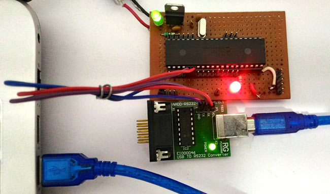
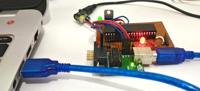
Hardware Setup and Testing the output:
The connection for this circuit is really simple, we use our PIC Perf board and just connect the three wires to RS232 to USB converter and connect the module to our computer using USB data cable as shown below.
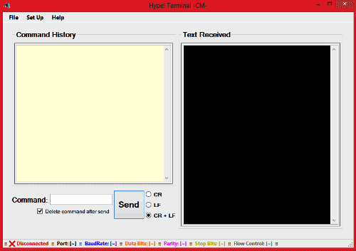
Next we install the Hyper Terminal Application (download it from here) and open it up. It should show something like this
Now open Device Manager on your computer and check which Com port your module is connected to, mine is connected to COM port 17 as shown below
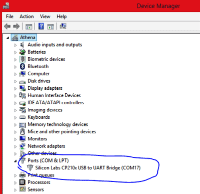
Note: The COM port name for your module might change according to your vendor, it is not a problem.
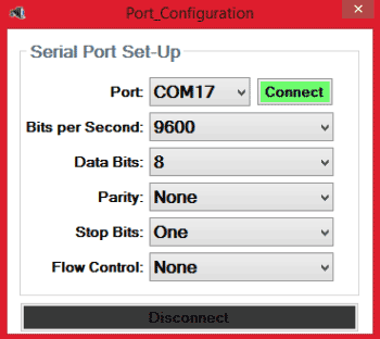
Now go back to Hyper Terminal Application and navigate to Set Up -> Port Configuration or press Alt+C, to get the following pop up box and select the desired port (COM17 in my case) in the pop-up window and click on connect.
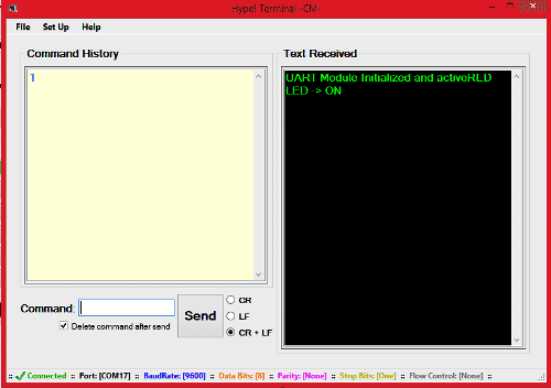
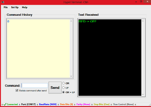
Once the connection is established turn on your PIC perf board and you should see something like this below

Keep your cursor in the Command Window and enter 1 then press enter. The LED will be turned on and the status will be displayed as shown below.
Same way , keep your cursor in the Command Window and enter 0 then press enter. The LED will be turned off and the status will be displayed as shown below.
Below are given the complete code and detailed video, which will show how the LED responds in real time for “1” and “0”.
That’s it guys, we have interfaced PIC UART with our computer and transferred the data to toggle the LED using Hyper terminal. Hope you understood, if not, use the comment section to ask your query. In our next tutorial we will again use UART but make it more interesting by using a Bluetooth module and broadcast the data over air.
Also check UART Communication between Two ATmega8 Microcontrollers and UART communication between ATmega8 and Arduino Uno.
Complete Project Code
// CONFIG

#pragma config FOSC = HS       // Oscillator Selection bits (HS oscillator)

#pragma config WDTE = OFF       // Watchdog Timer Enable bit (WDT disabled)

#pragma config PWRTE = OFF       // Power-up Timer Enable bit (PWRT enabled)

#pragma config BOREN = ON       // Brown-out Reset Enable bit (BOR enabled)

#pragma config LVP = OFF        // Low-Voltage (Single-Supply) In-Circuit Serial Programming Enable bit (RB3 is digital I/O, HV on MCLR must be used for programming)

#pragma config CPD = OFF        // Data EEPROM Memory Code Protection bit (Data EEPROM code protection off)

#pragma config WRT = OFF        // Flash Program Memory Write Enable bits (Write protection off; all program memory may be written to by EECON control)

#pragma config CP = OFF         // Flash Program Memory Code Protection bit (Code protection off)

// End of configuration
#include <xc.h>

#define _XTAL_FREQ 20000000

#define Baud_rate 9600
//***Initializing UART module for PIC16F877A***//

void Initialize_UART(void)

{

    //****Setting I/O pins for UART****//

    TRISC6 = 0; // TX Pin set as output

    TRISC7 = 1; // RX Pin set as input

    //________I/O pins set __________//


    /**Initialize SPBRG register for required

    baud rate and set BRGH for fast baud_rate**/

    SPBRG = ((_XTAL_FREQ/16)/Baud_rate) - 1;

    BRGH  = 1;  // for high baud_rate

    //_________End of baud_rate setting_________//


    //****Enable Asynchronous serial port*******//

    SYNC  = 0;    // Asynchronous

    SPEN  = 1;    // Enable serial port pins

    //_____Asynchronous serial port enabled_______//
    //**Lets prepare for transmission & reception**//

    TXEN  = 1;    // enable transmission

    CREN  = 1;    // enable reception

    //__UART module up and ready for transmission and reception__//


    //**Select 8-bit mode**//

    TX9   = 0;    // 8-bit reception selected

    RX9   = 0;    // 8-bit reception mode selected

    //__8-bit mode selected__//

}

//________UART module Initialized__________//

//**Function to send one byte of date to UART**//

void UART_send_char(char bt)

{

    while(!TXIF);  // hold the program till TX buffer is free

    TXREG = bt; //Load the transmitter buffer with the received value

}

//_____________End of function________________//

//**Function to get one byte of date from UART**//

char UART_get_char()

{

    if(OERR) // check for Error

    {

        CREN = 0; //If error -> Reset

        CREN = 1; //If error -> Reset

    }


    while(!RCIF);  // hold the program till RX buffer is free


    return RCREG; //receive the value and send it to main function

}

//_____________End of function________________//

//**Function to convert string to byte**//

void UART_send_string(char* st_pt)

{

    while(*st_pt) //if there is a char

        UART_send_char(*st_pt++); //process it as a byte data

}

//___________End of function______________//


// **********START of Main Function**************//

void main(void)

{

    int get_value;


    TRISB = 0x00; //Initialize PortB as output

    Initialize_UART();    //Initialize UART module


    UART_send_string("UART Module Initialized and active");    // Introductory Text


    while(1) //Infinite loop

    {

      get_value = UART_get_char();


        if (get_value == '1') //If the user sends "1"

        {

            RB3=1; //Turn on LED

            UART_send_string("RED LED -> ON"); //Send notification to the computer

            UART_send_char(10);//ASCII value 10 is used for carriage return (to print in new line)

        }


        if (get_value == '0') //If the user sends "0"

        {

           RB3=0; //Turn off LED

           UART_send_string("RED -> OFF"); //Send notification to the computer

           UART_send_char(10);//ASCII value 10 is used for carriage return (to print in new line)

        }


    }

}

// **********END of Main Function**************//
Comments
Its more similar like this tutorial
Once you understand how to use the USART module in PIC MCU, it should be easy for you to interface an RFID. If you find it hard try using it with Arduino and then migrate the code to PIC this was you can find the mistakes u r making!!
If you have any particular doubt use the Forum
A little correction
Hello! I just wanted to point an error in the explanation of both sections of Transmission and reception. According to the device's datasheet; when the TXREG is empty the TXIF will be set. İn the same way, when the RCREG register has finished the reception of a character, then the RCIF flag will be set and it remains set until we read the whole data which is in the 2deep FIFO register. In the program code sections the program is halted until the RCIF or TXIF bit is set as they should be.
Uart receive error and not transmit,
Hello Mr Raj,
Thank for your PIC post series, it is great your work for every beginner like me.
I had followed stricky this your Uart guide, but unlucky.
First times, when run hardware with USB-rs232 P9 convertor (without GND common to COM port of convertor)I can turn on/off LED (not receive any thing in ternminal), but after some my small change in code to send only one character or shorter string also on test board for better program over icsp which i did'nt recognized excactly which change is cause, i even now can not turn Led on/off also receive any thing. When i common ground PIC and COM convertor, i can receive sometimes some weird characters.
I had came back to simulate in Proteus with virtual terminal and oscilloscope to measure on A and C channel for rx/tx and i could see pules in channels but also didnt received any character also turn on/off LED.
My hardware board is supplied by 12v adapter over LM7805cv to 5v, pin 1 connected to pin 1 icsp with isolate circuit as PICkit2 datasheet.
Could you guide me how to investigate those error, Thank You alot for your any commend and guide!
Hi DoDung,
Hi DoDung,
I am sure I can help you, but sorry I could not undertstand your question properly. What do you mean by
"(without GND common to COM port of convertor)I can turn on/off LED (not receive any thing in ternminal),"
Were you able to toggle the LED, even though you dint receive anything on the serial monitor?
Thank for your soon reply, Mr
Thank for your soon reply, Mr Raj,
(without GND common to COM port of convertor :That means when
First time i tried in test board, i did'nt connect COM pin 5 to ground of test board but i could turn led on/off, but could not receive any thing on virtual terminal software. that is sames status for about 10 times. But after some small change with code also hardware, or even recover back your original code, i even can not turn led on/off any more.
When i connect COM pin 5 to ground of test board, sometimes i can see weird string in terminal (i understand that's for string in UART_init code), but still cannot turn led on/off. that means i can not transmit or receive any things.
Sorry i stiil find how to post my picture or attach file in this reply which captures pulses in rx/tx channels on Proteus oscilloscope emulation evironment
Dear Raj,
Dear Raj,
My simulation on proteus doesn't work as expected, nothing is received on terminal monitor, also I can't turn on/off LED. BUT Proteus virtual oscilloscope can capture some pulses when Initialize_UART also when I send 0 or 1 from HyperTerminal software.
I'm new of proteus also, I'm afraid of component values on proteus schematics also on test board make those errors? This webpage doesn't permit me to post picture so I post to my google drive https://drive.google.com/file/d/0B8Is2S9mjo25TG1zSVp4cjF0LUU/view?usp=sharing
Thank for your help!
Okay lets sort our simulation
Okay lets sort our simulation before we proceed with your hardware.
The simulation might not be working because of the following reasons, kindly check them out.
1. The Program is given or 20Mhz crystal osc. Double click on your crystal and make sure you have entered 20Mhz as the crystal value
2. The virtual terminal should be operating at 9600 baud rate. Double click on virtual terminal and check the same.
yes Mr Raj,
yes Mr Raj,
I have checked component values ,and also try all terminal types but still error.
Here is my component values :https://drive.google.com/open?id=0B8Is2S9mjo25UlZKSExnQ3B3ZXc
Thank for your help!
Hi DoDung,
Hi DoDung,
I just checked the simulation and program myself. It is working as expected here. So, the only problem that I could think of is still with your simulation file. Yes your screen schot shows that you have chaged the value of crystal to 20Mhz but what about inside your MCU. Double clcik on your PIC MCU in proteus and check the following two.
1. Processor clock Frequency should be 20Mhz
2. Load the correct hex file of the program. (Well! just mak sure its the same program)
[IMG]http://i64.tinypic.com/14df1p1.png[/IMG]
Thank Raj,
Thank Raj,
1-I had never think to change MCU frequence, i thought frequence from crystal, after change mcu freq from 1 to 20 Mhz, i can see weird string as pic https://drive.google.com/open?id=0B8Is2S9mjo25V28yM3o2eXZCOVk but still can not turn on/off LED
2- You mention to hex file that means MCU firmware, i click to MCU firmware and replace again your origin code and simulate again with same above state, have some warning as https://drive.google.com/open?id=0B8Is2S9mjo25b0ZlYkU2ZDU0bDQ
i casting example from UART_send_string("UART Module Initialized and active") to UART_send_string((char *)"UART Module Initialized and active"); to avoid warning but that 's for skip code warning only, simulation is same.
The warnings are fine. You
The warnings are fine. You don't have to worry about it.
But, if had compiled the code properly and have added the HEX file in proteus with 9600 baud rate and 20Mhz as crytal freq. You should have got the program working!!
Thank Mr Raj,
Thank Mr Raj,
Everything follow guide, but i'm still unlucky, i added max232 to simulation also to testboard and i had better result but still not complete it, not receive the exact expected result. I get ok result with other uart lesson (on test board, not well with simulation) which use C prinf function and BRGH = 0 also RCIE. I'm trying to understand that code fully and will come back to investigate my issue in your lesson.
Another way,I think i did'nt understand my proteus Hyper Terminal fully or it (Proteus 8.1) does not run exactly in Win7 64.
Thank Mr Raj and see you at your wifi lesson !
Hello Mr Raj,
Hello Mr Raj,
For update
After some days to test with some other guide, i just have ok result with your lesson by add max232 to test board. Anotherway, if i use max232 with virtual terminal in proteus simulation, i must set virtual terminal rx/tx inverted. And replace UART_send_char(10); by UART_send_char('\r');
Hope to get your help in your guide series.
Thank You Again!
Are you trying with the
Are you trying with the hardware now? Send a pic of your hardware with illustatrative connections.
Yes Mr Raj,
Yes Mr Raj,
Your lesson is ok with max232 on hardware also proteus simulation now.
https://drive.google.com/open?id=0B8Is2S9mjo25aHphSlVNTVBSdFE
https://drive.google.com/open?id=0B8Is2S9mjo25SU9EU1MwNWQwVlE
https://drive.google.com/open?id=0B8Is2S9mjo25eFYzUUJCN3RVXzg
https://drive.google.com/open?id=0B8Is2S9mjo25cExoTi1EWW90TEk
I am following your wifi lesson: https://circuitdigest.com/microcontroller-projects/interfacing-pic-microcontroller-with-esp8266
but i can not add component esp8266 on Proteus, it does not exist, how to get that wifi device on proteus, pls help!
Thank You!
Hi DoDung!
Hi DoDung!
Happy that you got your UART working.
For interfacing ESP8266 with PIC you do not have a simulation option. There is no way you can use a ESP8266 on a proteus. Hence you have to try it directly on the hardware. However you can use the simulation to verify if your Program is working as expected.
Thanks
Mine worked but keeps looping
Mine worked but keeps looping the text continuously on the virtual Terminal display Using Proteus.. why?
What text got looped
What text got looped continuously ?
Did you make any changes to the program?
related to uart
sir,in your programmed get value==1,but i was change
i am sending string like led on and off means get value==led on ; so what will do bro;
sir, In your program not
sir, In your program not display virtual terminal
sir i saw ur video and it is
sir i saw ur video and it is explained very nicely
RS232 to USB converter NOT
RS232 to USB converter NOT getting installed automatically as soon as you plug in the device. Please help me out by the process of installation.
i have got following msg
i have got following msg while compiling, cud u please the cause of error happened????
877A.c:94: warning: (359) illegal conversion between pointer types
pointer to const unsigned char -> pointer to unsigned char
877A.c:100: warning: (373) implicit signed to unsigned conversion
877A.c:103: warning: (359) illegal conversion between pointer types
pointer to const unsigned char -> pointer to unsigned char
877A.c:107: warning: (373) implicit signed to unsigned conversion
877A.c:110: warning: (359) illegal conversion between pointer types
pl help us.
Compiler error message 359
char should be a "const char", than it will compile without compiler error message "Illegal conversion between pointer types".
ERRORS IN EXECUTION OF UART PROGRAM.
SIR/I AM A RETIRED ENGINEER/PROFESSOR IN ELECTRONICS.IN MY COMPUTER I AM NOT FINDING ANY PORT/LPT UNDER DEVICE MANAGER.HENCE I AM NOT ABLE TO ASSIGN ANY PORT NUMBER IN THE HYPER-TERMINAL.ALSO IN PROTEUS I GET SOME GARBAGE MESSAGES WITH A VIRTUAL TERMINAL
TOGETHER WITH LED AT RB3 GLOWING.KINDLY HELP ME FIX UP THE ISSUES.WITH REGARDS/KRISHNAMOORTHY.
hey there...I was recently
hey there...I was recently trying to using the link in to find the hyper terminal application but i got an error saying page not found. i would just like to know if you can kindly suggest another source from which i can find a proper hyper terminal
uart not working properly
Hello sir,
I written the code for reading the ADC value and pass it to the PC using uart using pic16f688. But i am facing the problem in communication. I found that transmission is working properly because i am getting the Uart initilisation string on pc side. Problem is in reception. because when i give the character to read and trasmite back the adc value, i am getting nothing.
Please help me to solve this issue. I have given the code below :
PIC Code:
how can i read string of data on my uart
hello sir please how can i read bytes of data on my uart
I have a question. Is it also
I have a question. Is it also possible to create a function that receives a string (character array), just like the UART_send_string function?

bro,how to interface the rfid module with the pic?