
Whenever we go out of town for few days, we always used to worry about our plants as they need water on regular basis. So here we are making Automatic Plant Irrigation System using Arduino, which automatically provides water to your plants and keep you updated by sending message to your cell phone.
In This Plant Watering System, Soil Moisture Sensor checks the moisture level in the soil and if moisture level is low then Arduino switches On a water pump to provide water to the plant. Water pump gets automatically off when system finds enough moisture in the soil. Whenever system switched On or off the pump, a message is sent to the user via GSM module, updating the status of water pump and soil moisture. This system is very useful in Farms, gardens, home etc. This system is completely automated and there is no need for any human intervention. You can also build IoT based Soil Moisture Monitoring Device. On the other hand, if you are looking to build something very simple without using any microcontrollers like arduino then you can check out this simple automatic plant watering system project using the link.
Required Components for Arduino Plant Watering System Project
- Arduino Uno
- GSM Module
- Transistor BC547 (2)
- Connecting wires
- 16x2 LCD (optional)
- Power supply 12v 1A
- Relay 12v
- Water cooler pump
- Soil Moisture Sensor
- Resistors (1k, 10k)
- Variable Resister (10k, 100k)
- Terminal connector
- Voltage Regulator IC LM317
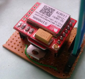
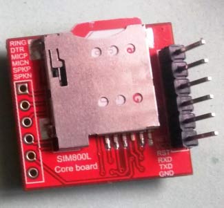
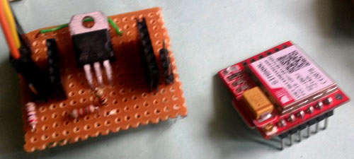
GSM Module:
Here we have used TTL SIM800 GSM module. The SIM800 is a complete Quad-band GSM/GPRS Module which can be embedded easily by customer or hobbyist. SIM900 GSM Module provides an industry-standard interface; the SIM800 delivers GSM/GPRS 850/900/1800/1900MHz performance for voice, SMS, Data with low power consumption. The design of this SIM800 GSM Module is slim and compact. It is easily available in the market or online from eBay.
- Quad - band GSM/GPRS module in small size.
- GPRS Enabled
- TTL Output
Learn more about GSM module and AT commands here. Also check our various projects using GSM and Arduino for properly understand their interfacing.
Circuit Explanation:
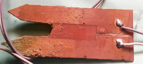
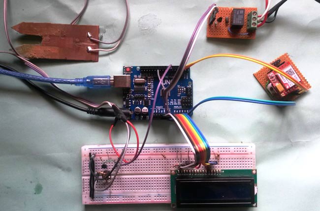
In this Plant Irrigation System, we have used a Homemade Soil Moisture Sensor Probe to sense the soil moisture level. To make probe, we have cut and etched a Copper clad Board according to the Picture shown below. One side of the probe is directly connected to Vcc and other probe terminal goes to the base of BC547 transistor. A potentiometer is connected to the base of the transistor to adjust the sensitivity of the sensor.
Arduino is used for controlling whole the process of this Automatic Plant Watering System. The output of soil sensor circuit is directly connected to digital pin D7 of Arduino. A LED is used at the sensor circuit, this LED’s ON state indicates the presence of moisture in the soil and OFF state indicates the absense of moisture in the soil.
GSM module is used for sending SMS to the user. Here we have used TTL SIM800 GSM module, which gives and takes TTL logic directly (user may use any GSM module). A LM317 Voltage regulator is used to power the SIM800 GSM module. LM317 is very sensitive to voltage rating and it is recommended to read its datasheet before use. Its operating voltage rating is 3.8v to 4.2v (please prefer 3.8v to operate it). Below is the Circuit Diagram of Power Supply given to the TTL sim800 GSM Module:
If user wants to use SIM900 TTL Module then he should use 5V and if the user wants to use SIM900 Module then apply 12v in the DC Jack slot of the board.
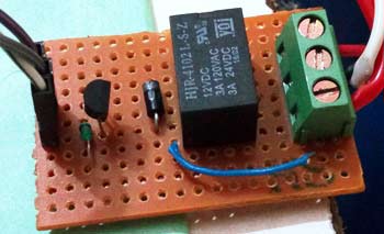
A 12V Relay is used to control the 220VAC small water pump. The relay is driven by a BC547 Transistor which is further connected to digital pin 11 of Arduino.
An optional LCD is also used for displaying status and messages. Control pins of LCD, RS and EN are connected to pin 14 and 15 of Arduino and data pins of LCD D4-D7 are directly connected at pin 16, 17, 18 and 19 of Arduino. LCD is used in 4-bit mode and driven by Arduino’s inbuilt LCD library.
Below is the circuit diagram of this Irrigation System with arduino and soil moisture sensor:

Working Explanation:
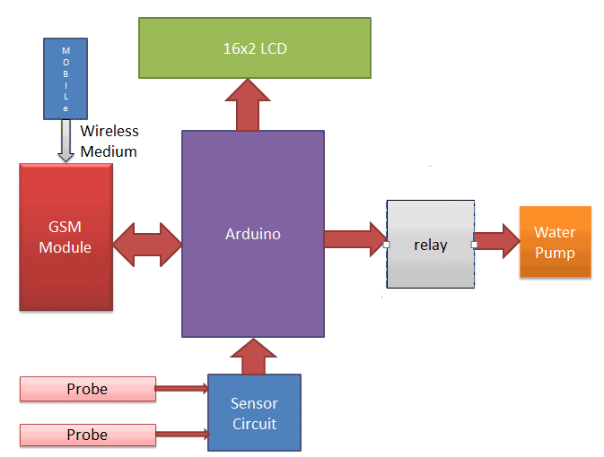
Working of this Automatic Plant Irrigation System is quite simple. First of all, it is a Completely Automated System and there is no need of manpower to control the system. Arduino is used for controlling the whole process and GSM module is used for sending alert messages to user on his Cellphone.
If moisture is present in soil then there is conduction between the two probes of Soil Moisture sensor and due to this conduction, transistor Q2 remains in triggered/on state and Arduino Pin D7 remains Low. When Arduino reads LOW signal at D7, then it sends SMS to user about “Soil Moisture is Normal. Motor turned OFF” and water pump remains in Off state.
Now if there is no Moisture in soil then Transistor Q2 becomes Off and Pin D7 becomes High. Then Arduino reads the Pin D7 and turns On the water motor and also sends message to user about “Low Soil Moisture detected. Motor turned ON”. Motor will automatically turn off when there is sufficient moisture in the soil. Further check the Demonstration Video and Code (given at the end) for better understanding the project working process.
Programming Explanation:
Code for this program is easily understandable. First of all we have included SoftwareSerial library to make pin 2 and 3 as Rx & Tx and also included LiquidCrystal for LCD. Then we defined some variables for motor, soil moisture sensor, LED etc.
#include<SoftwareSerial.h>
SoftwareSerial Serial1(2,3);
#include<LiquidCrystal.h>
LiquidCrystal lcd(14,15,16,17,18,19);
int led=13;
int flag=0;
String str="";
#define motor 11
#define sensor 7
Then in void setup () function, serial communication is initialized at 9600 bps and directions are given to the various Pins. gsmInit function is called for initialize the GSM module.
  Serial1.begin(9600);
  Serial.begin(9600);
  pinMode(led, OUTPUT);
  pinMode(motor, OUTPUT);
  pinMode(sensor, INPUT_PULLUP);
  lcd.print("Water Irrigaton");
  lcd.setCursor(4,1);
  delay(2000);
  lcd.clear();
  lcd.print("Circuit Digest");
  lcd.setCursor(0,1);
  lcd.print("Welcomes You");
  delay(2000);
  gsmInit();
Then sensor is read in void loop () function, and motor is turned on or off according to the sensor status and a SMS is also being sent to the user using sendSMS function. Check the various functions in full code given at the end.
void loop()
{
    lcd.setCursor(0,0);
    lcd.print("Automatic Mode    ");
    if(digitalRead(sensor)==1 && flag==0)
    {
      delay(1000);
      if(digitalRead(sensor)==1)
      {
        digitalWrite(led, HIGH);
        sendSMS("Low Soil Moisture detected. Motor turned ON");
        lcd.begin(16,2);
        lcd.setCursor(0,1);
        .... ......
        ..... ......
Here the gsmInit () function is important and users mostly find it difficult to set if properly. It is used to initialize the GSM module, where firstly GSM module is checked whether it is connected or not by sending ‘AT’ command to GSM module. If response OK is received, means it is ready. System keeps checking for the module until it becomes ready or until ‘OK’ is received. Then ECHO is turned off by sending the ATE0 command, otherwise GSM module will echo all the commands. Then finally Network availability is checked through the ‘AT+CPIN?’ command, if inserted card is SIM card and PIN is present, it gives the response READY. This is also check repeatedly until the network is found. This can be clearly understood by the Video below.
void gsmInit()
{
  lcd.clear();
  lcd.print("Finding Module..");
  boolean at_flag=1;
  while(at_flag)
  {
    Serial1.println("AT");
    while(Serial1.available()>0)
    {
      if(Serial1.find("OK"))
      at_flag=0;
    }
    delay(1000);
  }
  .... .....
  ..... .....
So with this Automatic Irrigation System, you don’t need to worry about your plants when you are away from your home. It can be further enhanced to be operated and monitored over the internet.
Complete Project Code
#include<SoftwareSerial.h>
SoftwareSerial Serial1(2,3);
#include<LiquidCrystal.h>
LiquidCrystal lcd(14,15,16,17,18,19);
int led=13;
int flag=0;
String str="";
#define motor 11
#define sensor 7
void setup()
{
  lcd.begin(16,2);
  Serial1.begin(9600);
  Serial.begin(9600);
  pinMode(led, OUTPUT);
  pinMode(motor, OUTPUT);
  pinMode(sensor, INPUT_PULLUP);
  lcd.print("Water Irrigaton");
  lcd.setCursor(4,1);
  delay(2000);
  lcd.clear();
  lcd.print("Circuit Digest");
  lcd.setCursor(0,1);
  lcd.print("Welcomes You");
  delay(2000);
  gsmInit();
  lcd.clear();
  lcd.print("System Ready");
}
void loop()
{
    lcd.setCursor(0,0);
    lcd.print("Automatic Mode    ");
    if(digitalRead(sensor)==1 && flag==0)
    {
      delay(1000);
      if(digitalRead(sensor)==1)
      {
        digitalWrite(led, HIGH);
        sendSMS("Low Soil Moisture detected. Motor turned ON");
        lcd.begin(16,2);
        lcd.setCursor(0,1);
        lcd.print("Motor ON    ");
        digitalWrite(motor, HIGH);
        delay(2000);
        flag=1;
      }
    }
    else if(digitalRead(sensor)==0 && flag==1)
    {
      delay(1000);
      if(digitalRead(sensor)==0)
      {
        digitalWrite(led, LOW);
        sendSMS("Soil Moisture is Normal. Motor turned OFF");
        digitalWrite(motor, LOW);
        lcd.begin(16,2);
        lcd.print("Motor OFF");
        lcd.setCursor(0,1);
        lcd.print("Motor OFF");
        delay(2000);
        flag=0;
      }
    }
}

void sendSMS(String msg)
{
  lcd.clear();
  lcd.print("Sending SMS");
  Serial1.println("AT+CMGF=1");
  delay(500);
  Serial1.print("AT+CMGS=");
  Serial1.print('"');
  Serial1.print("+919610126059");    // number
  Serial1.print('"');
  Serial1.println();
  delay(500);
  Serial1.println(msg);
  delay(500);
  Serial1.write(26);
  delay(1000);
  lcd.clear();
  lcd.print("SMS Sent");
  delay(1000);
  lcd.begin(16,2);
}
void gsmInit()
{
  lcd.clear();
  lcd.print("Finding Module..");
  boolean at_flag=1;
  while(at_flag)
  {
    Serial1.println("AT");
    while(Serial1.available()>0)
    {
      if(Serial1.find("OK"))
      at_flag=0;
    }
    delay(1000);
  }
  Serial1.println("ATE0");
  lcd.clear();
  lcd.print("Finding Network..");
  boolean net_flag=1;
  while(net_flag)
  {
    Serial1.println("AT+CPIN?");
    while(Serial1.available()>0)
    {
      if(Serial1.find("READY"))
      net_flag=0;
      break;
    }
    delay(1000);
  }
   Serial1.println("AT+CNMI=2,2,0,0,0");
   delay(1000);
   Serial1.println("AT+CMGF=1");
   delay(1000);
   Serial1.println("AT+CSMP=17,167,0,0");
   lcd.clear();
   Serial1.flush();
}
Comments
Hello,
I am totally new to Arduino, having never built anything. However, this is exactly what I am looking for to monitor moisture levels in a plant stacker system I am building. I have been searching the Internet and there are quite a few sites suggesting power should not be continually applied to the moisture sensor to prevent it from corroding. If I get one reading per hour it would be sufficient.
One way to accomplish this would be to connect it to a timer that powers it up every hour for long enough to take a reading, then powers it off again. But it seems there should be a better way.
Suggestions?
Copper does not corrode easily, its turns green on oxidation. Even if we dont give power it will corrode. But if you dont want to provide power for long duration then use some Timer ICs which can give long time period.
Nice think sir
I like your idea .I am also doing same project but I am not think ,thank you sir
in the code second line SoftwareSerial Serial1(2,3);
the software shows me to delete that line only .if i delete it the project will work or not
say me please
I want to do a project on "ardineo based solar automatice plant irrigation by voice mesage,with options .as, if we want to" ON press 1" and "if we want to OFF press 2".
Is this is useful for all layers of earth if one of the layer is wet land this sensor is useful for this layer land also
Hi...please I've implemented circuit and it works fine except for the GSM part. I don't receive the message even though LCD displays message sent. What could be the cause.
Did you find the solution? I am also experiencing trouble
GSM message not coming in mobile whereas in display it is shown
GSM based arduino programmable automatic irrigation system with water level indicator,moisture sensor and temperature sensor. When the gsm module receives a message from the user the arduino should check the water, moisture and temperature level and send these details to the user via text message. Receiving this message user can decide whether the motor should be switch on for a certain time period.According to the message from user motor should switch on.
As our project is same as yours.we have some doubt in programming.....So,please send your Arduino Programming for our reference.....As it will be usefull for us.
The program is already given above. All the best for your project
Please I am working on similar project but I am fining it difficult to simulate with proteus because the Arduino and the GSM module do not have some pins showing. Any assistance will be much appreciated. Thank you.
Hi,this is very informative about the project thanx for providing,,,i want to do this project for my final year should i go for it using microcontroller or through this aurdino based plx state which one will be easy using microntroller aurdino
Hi Mr Maddy, I am a student studying Irrigation Engineering, but I have a little bit background of electronics and arduino. Can I have all the components you have used in your projects and their functions, as well as comments in every stage of your arduino code, so that I will be able to follow, I want to do a final project like this one, of integrating electronics in irrigation systems. I will be glad if you use the above email. Thank you in advance
Hi, i have started with this project , But i got stuck in between and i dont know where the mistake is. when i connect Arduino with gsm module, the circuit goes off. and I am using gsm 900.can you send me the proper circuit diagram and code to the above mail. thank you : )
I m facing problem that while running code output is always high,means relay is always on .
And if condition is running ....its print statement are displayed on lcd but loW condition noT running.
What cud be the reason
- You may have messed up the circuitry. Check again what goes where. (Maybe you have connected the transistor wrong?)
- You may be using a wrong or faulty transistor to control the relay. (Maybe you are using a PNP instead of an NPN one?)
- (If you have modified the code) you may have messed up some command. (Maybe you are sending "digitalWrite(motor, HIGH)" when you should send "LOW" instead).
We have the same problem.
Please help me bro .
please help me in doing this project i was messed up with this circuit diagram i need your contact
pleas give me inforamation about that becoz i am making project in that
Hi , is ok to use a submersible water pump ? and can u make a diagram for your breadboard pls . I am making this project of yours . pls help me Thank You :)
hii im using sim800a type gsm module. check wheather my module outout is ttl or not..?
I want to buy this project...can u help me ????
in the above given project ,where u have assigned the analog pin for moisture sensor in arduino uno..
Hi gopi,
In this project the moisture sensor is used as a digital sensor and it is connected to digital pin 7 of Arduino
hello,
i am doing this project but unable to get the 3.8v output from the ckt dig.and the relay is also not working when connected to ckt.i check the relay is not damaged.so can u help me please.
Thank you your kindly effort. I haven't any comments. Thank you again.
Dear Colleagues,
I implemented this circuit but want to add remote control functionality using SMS by the user. How can I improve the code to enable to remotely control the system using SMS ie overriding the automation when arises.
Hi! I'd like to do this project for school, but the GSM module isn't available. How must I modify this so that it would not require using the GSM module? Thanks! ;)
plss tell me the connection gsm to arduino
Pls send a clear photo of circuit and simple connection diagram
how can use in by solar pannel
Hello,
can I get the schematic of the project using the Fritzing software?
I want to etch the circuit on a printed circuit board.
hi im jasper i need your help to this project of your's about the circuit im little confuse about set up
Thank you so much sir for this helpfull project.
i m sure i will work on it
before it i have work on gsm based home automation
but in that project there is problem the pin no. 3 is continously providing the voltage
can u please help me regarding to that project
can u please help me to know about the gsm library and other liabrary
sir i need ur cellphone number
hello,thanks for uploading this paper,i`ve been working on this.But i am confusing about what software you use for that circuit digest in your paper?
Hello, can i know how to get the GSM Module in library proteus ?
This code is not upload to ARDUINO...plz another code & Diagram is sent in my email address
Hello! We are doing a model of this for a Electrovagenza and every part of it is working except for the motor part. Motor is running due to the AC supply and not through the relay circuit. (Can you please mention the diode part number used in the circuit and is it compulsory?). Speedy reply would be much appreciated.
Hey, When I tried to run the code in Arduino's programming software. It showed me some errors. Can you please find those and send me ASAP.
We can off motor with sms by mobile?
Yes you can, but you have to edit the program for that. Program the arduino to read any incoming message from GSM module and turn of that GPIO pin. Refer the AT command list of GSM module to know how to read text message using Arduino
How can I use rain sensor with it. Please help me.
can i get the brief circuit design of this pls..
i am facing problem with gsm module and sensor and iam very confused with the circuit diagram given above can u please help me in fixing this??
Hi. I am doing this as my level 3 project i would like to get a clearer schemetic and circuit diagram for this circuit, also if someone has attempted this project can you please tell me whether it works properly or not? Much appreciated

This is a fine way to explain these mini micros. Thank you this morning for waking me up.