 Anand D
Author

In this tutorial, we are going to see how you can create a custom Graphical User Interface(GUI) using LVGL and our favourite Arduino IDE. You can use any kind of microcontroller for this project; the only thing you need to do is to include the right pins in the Arduino code. Here, I’m using an ESP32-C3 based smartwatch for the demonstration. This has a display, touch, controller and everything integrated inside, so we don't want to make any messy wiring. Whether you are a hobbyist building a home-automation dashboard or a product developer prototyping a wearable UI, mastering LVGL on ESP32 with Arduino is one of the highest-leverage skills you can add to your embedded toolkit.
Table of Contents
What Is LVGL? - Introduction to the Light and Versatile Graphics Library
LVGL stands for Light and Versatile Graphics Library, which is an open-source library that supports a wide variety of microcontrollers and displays. It’s a collection of components required to build a Graphical User Interface (GUI), mostly in embedded systems where custom UIs are needed. Examples include a Smart Home Automation & Monitoring Hub, a Desk32 Smart Hub for deep work focus, or even a Smart Wellness Clock that shows health metrics at a glance.
You will be able to see GUIs built on top of LVGL around you, like your smartwatch screens or display dashboards of some Attendance Systems in some offices. Developers use LVGL in a wide variety of ways, like some build GUIs using raw code while some others use some Drag-and-Drop visual editors like Square Line Studio or EEZ Studio that support LVGL. Here in this tutorial, we will use example code snippets provided by LVGL in their documentation to build a GUI out of it.
LVGL at a Glance
| Feature | Detail |
| Full name | Light and Versatile Graphics Library |
| Language | C99 (C++ wrappers available) |
| License | MIT — free for commercial use |
| Minimum RAM | ~32 kB (typical embedded target) |
| Minimum Flash | ~128 kB |
| Supported MCUs | ESP32, STM32, RP2040, Arduino, NXP and more |
| Display interfaces | SPI, Parallel, RGB, MIPI-DSI |
| Visual editors | SquareLine Studio, EEZ Studio |
| Arduino library | Available in Arduino Library Manager |
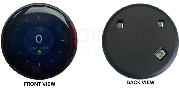
Hardware Used - ESP32-2424S012 Round Display Development Board
Let’s talk a little bit about the ESP32 C3 based development board that we use in this tutorial. First of all, it has an ESP32-C3 at its core. It has a 1.28” 240 * 240 round LCD display on top. The display uses the famous GC9A01 display driver, which is seen in many hobby-level round display modules. It uses the 7-pin SPI interface (SCL, SDA, DC, CS, RST, 3V3, GND) for communication. The touch IC used is CST816D. It has a battery charging IC, which is IP5306. You can use any display or controller for this tutorial; the only thing you need to do is modify the configurations to match your device.
What Do You Need Before Getting Started?
- An ESP32-based development board that has either SPI or a parallel display connection.
- Capacitive/Resistive Touch Controller – optional but strongly advised.
- USB-C or Micro-USB cable for programming.
- 3.7V LiPo Battery – optional (in case of standalone functionality).
Software Prerequisites
- Arduino IDE 2.x – download from Arduino.cc.
- ESP32 board package – available on Arduino Boards Manager (https://raw.githubusercontent.com/espressif/arduino-esp32/gh pages/package_esp32_index.json).
- LVGL for Arduino library – available from Arduino Library Manager ("lvgl").
- Driver files of the display and touch controller - CST816D.h, CST816D.cpp – obtain from project GitHub repo.
Knowledge Prerequisites
- Basic syntax of Arduino C++ code – setup/loop methods.
- I²C/SPI protocol knowledge.
- GPIO mapping knowledge of the ESP32 board.
ESP32-2424S012 Full Specifications
| Weight | 20g |
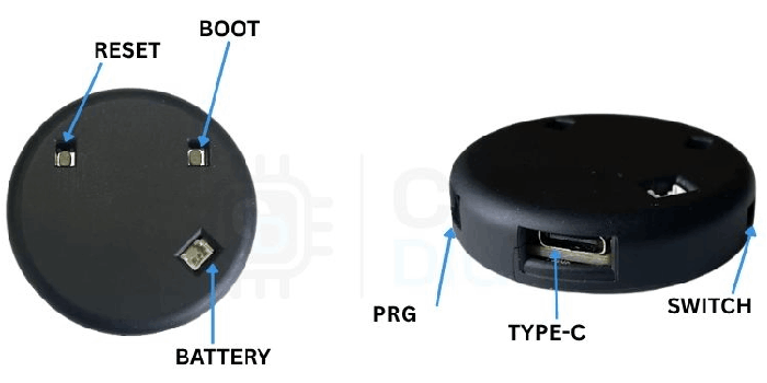
You can power the module either via the Type-C connector that’s available on board or using a 3.7V LiPo battery by connecting it to the 2-pin JST connector in the back of the module.
Step-by-Step Setup: LVGL Arduino GUI on ESP32
Step 1 ⇒ Install the LVGL Library in Arduino IDE
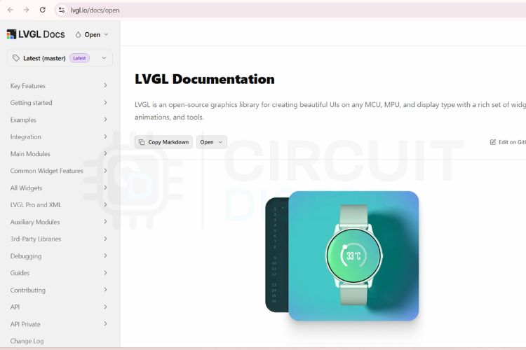
You need to go to the Arduino Library Manager and search for lvgl. Install the latest release by kisvegabor. Now, you need to head over to the official documentation of LVGL.
Step 2 ⇒ Browse the LVGL Widget Documentation
In this tutorial, we are going to build a simple switch project using LVGL and Arduino IDE.
We can make this project in several different ways - meaning using LVGL and without using LVGL. From my experience, if we build a custom GUI using LVGL, we get a smartphone app kind of quality for the UI. This is because LVGL has a mature set of design components and animations that outperform any other competitors like TFT_eSPI.
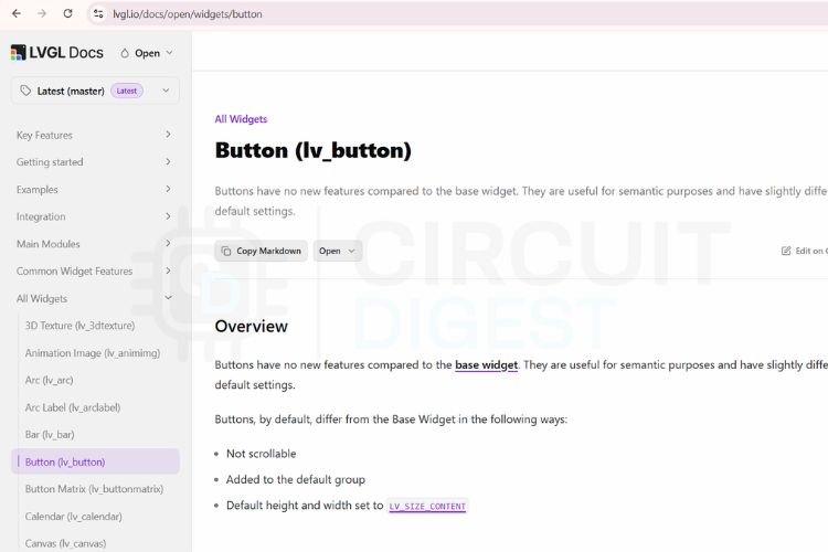
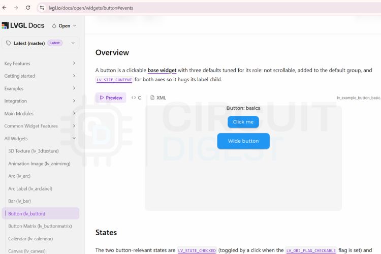
Now, let’s go to All Widgets > Button
This opens the button widgets available in LVGL. You can see a lot of example widgets for buttons.
Let’s scroll down and go to the first example. You can see options for Preview - meaning see how the button functions, and Code - meaning see the code snippet for that particular button.
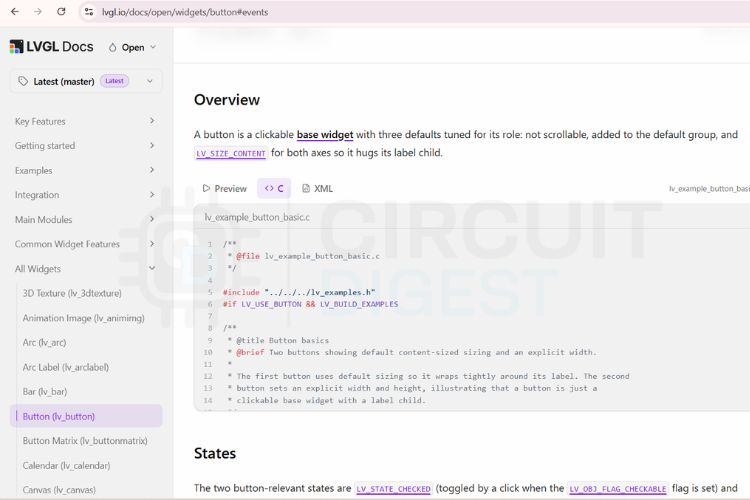
Step 3⇒ Copy the Code Snippet
Let’s open the code snippet part of the example, which reveals the code behind the preview.
Step 4⇒ Understand the Project Folder Structure
Let’s copy the code from that section. If you check out the GitHub repo mentioned below, you will be able to download all the code for this project. You will be able to see three files along with the main Arduino code, as shown below.
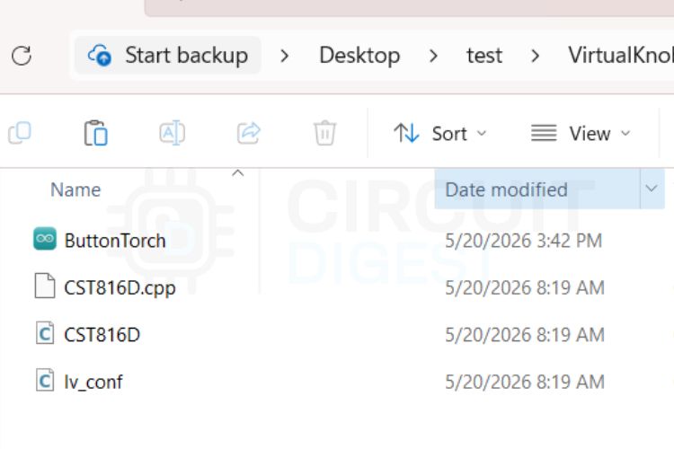
You have the main Arduino code, then the LVGL configuration file named lv_conf and then the touch configuration files, which are CST816D.cpp and CST816D.h. For this tutorial, we just need to modify the main Arduino code with the code snippet that we just copied. You may need to modify the pin configurations as per your setup.
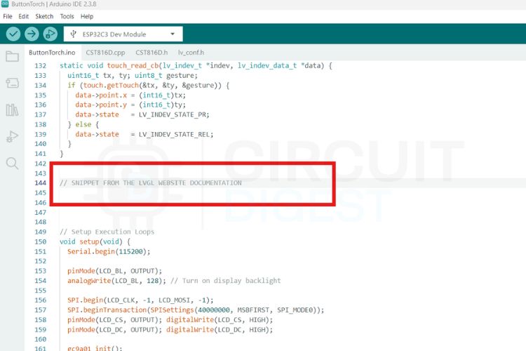
Step 5⇒ Paste the Snippet into the Arduino Sketch
Once the Arduino code is opened, you can see a section asking for “SNIPPET FROM THE LVGL WEBSITE DOCUMENTATION”. Paste the code snippet in this section. This code now gives the same button transitions in the display as we saw in the preview in the documentation.
The modified code snippet is attached to the code provided on GitHub.
Select the right board and right port in your Arduino IDE and hit the upload button.
Step 7 ⇒ Test the Result
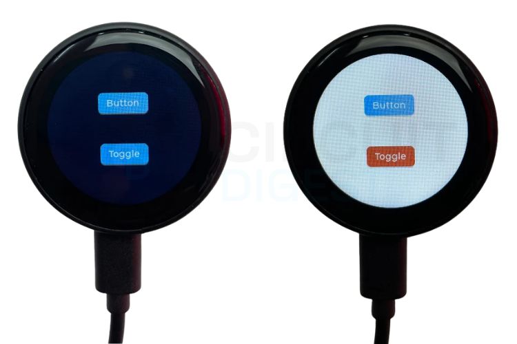
Once the code is successfully uploaded, you can see the screen displaying the buttons exactly in the same way as shown in the preview in the LVGL documentation. You can see the button animations as well when you press the buttons. As we modified the code to change the screen background to white when the toggle button is turned on, you can see the background colour turning to white and black when we turn on and off the toggle button, as shown below. This is an excellent LVGL ESP32 project to study after completing the basic tutorial.
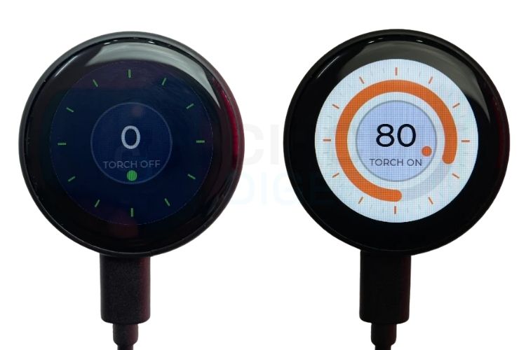
You can see another folder in the same repo named VirtualTorch. This project is shared for your future reference. It’s an advanced version of this tutorial that has a button for the torch and a slider around the button to adjust the brightness, too. Below are the two screens of the VirtualTorch project, before the button is pressed and after the button is pressed and the slider adjusted.
Code Explanation: How the LVGL Arduino Sketch Works
1. Library Includes and Configuration
#define LV_CONF_INCLUDE_SIMPLE
#include <lvgl.h>
#include <SPI.h>
#include <Wire.h>
#include "CST816D.h
Include the essential libraries, the configuration file, which is lv_config.h and the touch driver, which is CST816D.
2. GPIO Pin Definitions
#define LCD_CLK  6
#define LCD_MOSI 7
#define LCD_DC   2
#define LCD_CS   10
#define LCD_BL   3
#define TP_SDA   4
#define TP_SCL   5
#define TP_INT   0
#define TP_RST   1
#define LCD_W    240
#define LCD_H    240
3. Low-Level Display Helper Functions
Configure the GPIO pins of the display and touch with the ESP32.
static void lcd_cs(bool sel)  { digitalWrite(LCD_CS, sel ? LOW : HIGH); }
static void lcd_cmd(uint8_t c){ digitalWrite(LCD_DC, LOW);  SPI.transfer(c); }
static void lcd_dat(uint8_t d){ digitalWrite(LCD_DC, HIGH); SPI.transfer(d); }
4. LVGL Porting / Flush Callback
Helper functions for talking to the GC9A01 display.
static void gc9a01_init(void) {
 lcd_cs(true);
 lcd_cmd(0xEF);
 lcd_cmd(0xEB); lcd_dat(0x14);
 lcd_cmd(0xFE);
 lcd_cmd(0xEF);
 lcd_cmd(0xEB); lcd_dat(0x14);
 lcd_cmd(0x84); lcd_dat(0x40);
 lcd_cmd(0x85); lcd_dat(0xFF);
 lcd_cmd(0x86); lcd_dat(0xFF);
 lcd_cmd(0x87); lcd_dat(0xFF);
 lcd_cmd(0x88); lcd_dat(0x0A);
 lcd_cmd(0x89); lcd_dat(0x21);
 lcd_cmd(0x8A); lcd_dat(0x00);
 lcd_cmd(0x8B); lcd_dat(0x80);
 lcd_cmd(0x8C); lcd_dat(0x01);
 lcd_cmd(0x8D); lcd_dat(0x01);
 lcd_cmd(0x8E); lcd_dat(0xFF);
 lcd_cmd(0x8F); lcd_dat(0xFF);
 lcd_cmd(0xB6); lcd_dat(0x00); lcd_dat(0x20);
 lcd_cmd(0x36); lcd_dat(0x08);
 lcd_cmd(0x3A); lcd_dat(0x05);
 lcd_cmd(0x90); lcd_dat(0x08); lcd_dat(0x08); lcd_dat(0x08); lcd_dat(0x08);
 lcd_cmd(0xBD); lcd_dat(0x06);
 lcd_cmd(0xBC); lcd_dat(0x00);
 lcd_cmd(0xFF); lcd_dat(0x60); lcd_dat(0x01); lcd_dat(0x04);
 lcd_cmd(0xC3); lcd_dat(0x13);
 lcd_cmd(0xC4); lcd_dat(0x13);
 lcd_cmd(0xC9); lcd_dat(0x22);
 lcd_cmd(0xBE); lcd_dat(0x11);
 lcd_cmd(0xE1); lcd_dat(0x10); lcd_dat(0x0E);
 lcd_cmd(0xDF); lcd_dat(0x21); lcd_dat(0x0C); lcd_dat(0x02);
 lcd_cmd(0xF0); lcd_dat(0x45); lcd_dat(0x09); lcd_dat(0x08);
                lcd_dat(0x08); lcd_dat(0x26); lcd_dat(0x2A);
 lcd_cmd(0xF1); lcd_dat(0x43); lcd_dat(0x70); lcd_dat(0x72);
                lcd_dat(0x36); lcd_dat(0x37); lcd_dat(0x6F);
 lcd_cmd(0xF2); lcd_dat(0x45); lcd_dat(0x09); lcd_dat(0x08);
                lcd_dat(0x08); lcd_dat(0x26); lcd_dat(0x2A);
 lcd_cmd(0xF3); lcd_dat(0x43); lcd_dat(0x70); lcd_dat(0x72);
                lcd_dat(0x36); lcd_dat(0x37); lcd_dat(0x6F);
 lcd_cmd(0xED); lcd_dat(0x1B); lcd_dat(0x0B);
 lcd_cmd(0xAE); lcd_dat(0x77);
 lcd_cmd(0xCD); lcd_dat(0x63);
 lcd_cmd(0x70); lcd_dat(0x07); lcd_dat(0x07); lcd_dat(0x04);
                lcd_dat(0x0E); lcd_dat(0x0F); lcd_dat(0x09);
                lcd_dat(0x07); lcd_dat(0x08); lcd_dat(0x03);
 lcd_cmd(0xE8); lcd_dat(0x34);
 lcd_cmd(0x62); lcd_dat(0x18); lcd_dat(0x0D); lcd_dat(0x71);
                lcd_dat(0xED); lcd_dat(0x70); lcd_dat(0x70);
                lcd_dat(0x18); lcd_dat(0x0F); lcd_dat(0x71);
                lcd_dat(0xEF); lcd_dat(0x70); lcd_dat(0x70);
 lcd_cmd(0x63); lcd_dat(0x18); lcd_dat(0x11); lcd_dat(0x71);
                lcd_dat(0xF1); lcd_dat(0x70); lcd_dat(0x70);
                lcd_dat(0x18); lcd_dat(0x13); lcd_dat(0x71);
                lcd_dat(0xF3); lcd_dat(0x70); lcd_dat(0x70);
 lcd_cmd(0x64); lcd_dat(0x28); lcd_dat(0x29); lcd_dat(0xF1);
                lcd_dat(0x01); lcd_dat(0xF1); lcd_dat(0x00); lcd_dat(0x07);
 lcd_cmd(0x66); lcd_dat(0x3C); lcd_dat(0x00); lcd_dat(0xCD);
                lcd_dat(0x67); lcd_dat(0x45); lcd_dat(0x45);
                lcd_dat(0x10); lcd_dat(0x00); lcd_dat(0x00); lcd_dat(0x00);
 lcd_cmd(0x67); lcd_dat(0x00); lcd_dat(0x3C); lcd_dat(0x00);
                lcd_dat(0x00); lcd_dat(0x00); lcd_dat(0x01);
                lcd_dat(0x54); lcd_dat(0x10); lcd_dat(0x32); lcd_dat(0x98);
 lcd_cmd(0x74); lcd_dat(0x10); lcd_dat(0x85); lcd_dat(0x80);
                lcd_dat(0x00); lcd_dat(0x00); lcd_dat(0x4E); lcd_dat(0x00);
 lcd_cmd(0x98); lcd_dat(0x3E); lcd_dat(0x07);
 lcd_cmd(0x35);
 lcd_cmd(0x21);
 lcd_cmd(0x11); delay(120);
 lcd_cmd(0x29); delay(20);
 lcd_cs(false);
}
static void gc9a01_set_window(uint16_t x0, uint16_t y0, uint16_t x1, uint16_t y1) {
 lcd_cmd(0x2A); lcd_dat(x0 >> 8); lcd_dat(x0 & 0xFF); lcd_dat(x1 >> 8); lcd_dat(x1 & 0xFF);
 lcd_cmd(0x2B); lcd_dat(y0 >> 8); lcd_dat(y0 & 0xFF); lcd_dat(y1 >> 8); lcd_dat(y1 & 0xFF);
 lcd_cmd(0x2C);
}
// LVGL Porting Layer Setup
static lv_display_t *g_disp;
static uint8_t g_buf1[LCD_W * 20 * 2];
static uint8_t g_buf2[LCD_W * 20 * 2];
static void flush_cb(lv_display_t *disp, const lv_area_t *area, uint8_t *px_map) {
 uint32_t npx = (uint32_t)(area->x2 - area->x1 + 1) * (area->y2 - area->y1 + 1);
 lcd_cs(true);
 gc9a01_set_window(area->x1, area->y1, area->x2, area->y2);
 digitalWrite(LCD_DC, HIGH);
 SPI.writeBytes(px_map, npx * 2);
 lcd_cs(false);
 lv_display_flush_ready(disp);
}
CST816D touch(TP_SDA, TP_SCL, TP_RST, TP_INT);
static void touch_read_cb(lv_indev_t *indev, lv_indev_data_t *data) {
 uint16_t tx, ty; uint8_t gesture;
 if (touch.getTouch(&tx, &ty, &gesture)) {
   data->point.x = (int16_t)tx;
   data->point.y = (int16_t)ty;
   data->state   = LV_INDEV_STATE_PR;
 } else {
   data->state   = LV_INDEV_STATE_REL;
 }
}
Above is the LVGL interface layer, which interfaces our hardware, the ESP32 display and touch with THE LVGL library.
5. Event Handler and Button Widget (LVGL Snippet)
static void event_handler(lv_event_t * e)
{
   lv_event_code_t code = lv_event_get_code(e);
   lv_obj_t * target = (lv_obj_t *)lv_event_get_target(e); // Get which widget was interacted with
   if(code == LV_EVENT_CLICKED) {
       Serial.println("Clicked");
   }
   else if(code == LV_EVENT_VALUE_CHANGED) {
       Serial.println("Toggled");
       // Check if the widget that fired the event is currently checked (turned ON)
       if(lv_obj_has_state(target, LV_STATE_CHECKED)) {
           // Toggle is ON -> Turn active screen background to White
           lv_obj_set_style_bg_color(lv_screen_active(), lv_color_white(), LV_PART_MAIN);
       } else {
           // Toggle is OFF -> Turn active screen background back to Black/Dark slate
           lv_obj_set_style_bg_color(lv_screen_active(), lv_color_hex(0x151525), LV_PART_MAIN);
       }
   }
}
void lv_example_button_1(void)
{
   lv_obj_t * label;
   lv_obj_t * btn1 = lv_button_create(lv_screen_active());
   lv_obj_add_event_cb(btn1, event_handler, LV_EVENT_ALL, NULL);
   lv_obj_align(btn1, LV_ALIGN_CENTER, 0, -40);
   lv_obj_remove_flag(btn1, LV_OBJ_FLAG_PRESS_LOCK);
   label = lv_label_create(btn1);
   lv_label_set_text(label, "Button");
   lv_obj_center(label);
   lv_obj_t * btn2 = lv_button_create(lv_screen_active());
   lv_obj_add_event_cb(btn2, event_handler, LV_EVENT_ALL, NULL);
   lv_obj_align(btn2, LV_ALIGN_CENTER, 0, 40);
   lv_obj_add_flag(btn2, LV_OBJ_FLAG_CHECKABLE);
   lv_obj_set_height(btn2, LV_SIZE_CONTENT);
   label = lv_label_create(btn2);
   lv_label_set_text(label, "Toggle");
   lv_obj_center(label);
}
Above is the snippet that we copied from the LVGL Documentation. It has two parts or two functions. First is an event_handler(), which is the UI part of the snippet. It builds the two buttons using the same widget template that we chose from the documentation.
6. setup() - Hardware and LVGL Initialisation
The second part is the lv_example_button_1(), which performs the whole logic of the two buttons.
void setup(void) {
 Serial.begin(115200);

 pinMode(LCD_BL, OUTPUT);
 analogWrite(LCD_BL, 128); // Turn on display backlight
 SPI.begin(LCD_CLK, -1, LCD_MOSI, -1);
 SPI.beginTransaction(SPISettings(40000000, MSBFIRST, SPI_MODE0));
 pinMode(LCD_CS, OUTPUT); digitalWrite(LCD_CS, HIGH);
 pinMode(LCD_DC, OUTPUT); digitalWrite(LCD_DC, HIGH);
 gc9a01_init();
 Wire.begin(TP_SDA, TP_SCL);
 touch.begin();
 // Initialize display engine
 lv_init();
 g_disp = lv_display_create(LCD_W, LCD_H);
 lv_display_set_color_format(g_disp, LV_COLOR_FORMAT_RGB565_SWAPPED);
 lv_display_set_flush_cb(g_disp, flush_cb);
 lv_display_set_buffers(g_disp, g_buf1, g_buf2, sizeof(g_buf1), LV_DISPLAY_RENDER_MODE_PARTIAL);
 // Initialize touch input pointer
 static lv_indev_t * indev = lv_indev_create();
 lv_indev_set_type(indev, LV_INDEV_TYPE_POINTER);
 lv_indev_set_read_cb(indev, touch_read_cb);
 // Set dark canvas background
 lv_obj_set_style_bg_color(lv_screen_active(), lv_color_hex(0x151525), LV_PART_MAIN);
 // EXECUTE COPIED SNIPPET
 lv_example_button_1();
}
This is the setup() loop that fires exactly once when the device boots. It initialises the hardware in a sequential order, like turning on the display backlight, then initialising the display engine, then the touch.
7. loop() - LVGL Tick and Timer
void loop(void) {
 lv_tick_inc(5);
 lv_timer_handler();
 delay(5);
}
Once setup() completes, the ESP32 executes the loop() continuously that runs the app.
Modern Arduino Display System using LVGL - Full Tutorial with Video
Troubleshooting Common LVGL Arduino ESP32 Issues
| Symptom | Likely Cause | Fix |
| Blank white screen | Wrong SPI pins or backlight not enabled | Verify LCD_CLK, LCD_MOSI, LCD_CS, LCD_DC; add digitalWrite(LCD_BL, HIGH); |
| Touch not responding | Wrong SDA/SCL pins or missing touch.begin() | Check TP_SDA / TP_SCL defines; ensure touch.begin(); is inside setup() |
| lv_conf.h: No such file or directory | lv_conf.h missing from sketch folder | Copy lv_conf_template.h to the sketch folder, rename to lv_conf.h, set #if 1 |
| Sketch too big / out of flash | Unused LVGL widgets are consuming flash | Disable unused widgets in lv_conf.h: #define LV_USE_CHART 0 |
| Display colours wrong/ inverted | Incorrect colour format setting | Try LV_COLOR_FORMAT_RGB565 instead of LV_COLOR_FORMAT_RGB565_SWAPPED |
| Touch coordinates mirrored | Display and touch orientation mismatch | Swap X/Y or negate the axis in touch_read_cb() |
LVGL vs TFT_eSPI
| Factor | LVGL | TFT_eSPI |
| Widget system | Full widget library (buttons, sliders, charts…) | None — manual drawing only |
| Animation engine | Built-in, hardware-accelerated | None built-in |
| Touch input handling | Built-in input device abstraction | Manual polling required |
| Memory overhead | Higher (frame buffer + widget tree) | Lower |
| Learning curve | Moderate (port layer setup required) | Low (simple API) |
| UI quality ceiling | Smartphone-grade | Basic / custom shapes |
| Visual editors | SquareLine Studio, EEZ Studio | None |
| Best for | Product UIs, dashboards, wearables | Simple graphics, gauges, fonts |
Arduino LVGL GitHub
Explore open-source Arduino and LVGL projects on GitHub to build modern embedded GUI applications with touch-enabled displays. Find libraries, sample interfaces, and hardware integration examples that simplify creating responsive and visually rich IoT dashboards.


Conclusion
From this tutorial, we came to understand how to properly use the free and open-source graphical library called LVGL, which is used to develop GUIs for embedded systems. We can use our own hobby-level microcontrollers like the ESP32 or similar ones to run such programs. The future is endless, you can create your own embedded systems projects, home automations or any other projects requiring custom GUIs. You can refer to the codes provided in the GitHub repo for any future references. If you would like to see how we can implement LVGL in a real-life project, check out our Voice-Activated LED Controller using ESP32S3 project. For inspiration, take a look at how display-based interfaces can be applied in a radar-based human presence and fall detection system, a great example of combining sensor data with a meaningful on-screen interface.
Frequently Asked Questions
⇥ Why is LVGL used with Arduino?
The LVGL (Light and Versatile Graphics Library), which is an open-source C library for developing touch-interactive GUIs on microcontrollers, can be used with Arduino, as it integrates well with the Arduino platform; is compatible with the ESP32 and many other popular boards; and produces smartphone-quality animations and widgets without a separate GPU.
⇥ Can I use LVGL with Arduino IDE?
Yes, LVGL works with Arduino IDE. You just need the LVGL Library installed.
⇥ What is lv_conf.h?
lv_conf.h is the LVGL configuration file.
⇥ Why do we need CST816D.cpp and CST816D.h?
These files are the touch controller driver. They help the ESP32 communicate with the CST816D touch IC using I2C.
⇥ Which communication protocols are used here?
SPI for display communication, I2C for touch communication and UART for serial programming.
⇥ Can I use another display instead of GC9A01?
Yes, you only need the correct display driver and pin configurations of your display.
⇥ Can I make custom UIs instead of using widgets?
Yes, LVGL allows custom drawing, animations, gradients, gauges, etc...
Touch-Based GUI Projects
Explore interactive touch-enabled GUI projects built using modern microcontrollers and display modules for smart control, automation, and real-time monitoring applications. These projects demonstrate intuitive user interfaces with responsive controls, animations, and sensor integration for a seamless embedded experience.

Getting Started with Image Processing using MATLAB
MATLAB can perform many advanced image processing operations, but for getting started with Image processing in MATLAB, here we will explain some basic operations like RGB to Grey, rotating the image, binary conversion, etc.

Raspberry Pi-Based Jarvis-Themed Speaking Alarm Clock
At the end of this project, we will create a very basic GUI using which we can set an alarm and when the alarm goes off, we will have a voice which tells us the current time and day with some pre-defined text. Sounds cool, right!! So let us build one.

How to Set a Static IP on Raspberry Pi?
If your Raspberry Pi IP address static configuration is changing too often, this complete guide is going to demonstrate how to configure a Raspberry Pi to use static IP through NetworkManager (using nmcli) and desktop GUI methods.
