

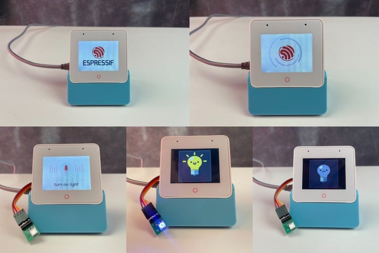
Voice control has become an integral part of modern smart home automation. In this tutorial, we build a voice-controlled LED system using the ESP32-S3-BOX-3 development board, combining wake word detection, speech recognition, touch interface, and audio feedback to create an intelligent control system. The code will be based on the factory example provided by Espressif and we will do the needed modifications to make it apt for our project.
The ESP32-S3-BOX-3 is a powerful development platform from Espressif that integrates a 320×240 touchscreen display, dual microphones for voice input, stereo speakers, and WiFi/Bluetooth connectivity. This project demonstrates how to leverage these features using the ESP-IDF (Espressif IoT Development Framework) and ESP-SR (Speech Recognition) library.
For a detailed hands-on review and getting-started walkthrough of the ESP32-S3-BOX-3 board, check out our previous articles on the same
Getting Started with ESP32-S3-BOX-3 - CircuitDigest Review
Programming ESP32-S3-BOX-3 with Arduino IDE - RGB LED Control
What You'll Learn
- Implementing wake word detection using WakeNet
- Building command recognition with MultiNet
- Creating a touch-based GUI using the LVGL library
- Playing audio feedback through the I2S interface
- Controlling hardware (LED) through GPIO
Components Required
| S.No | Component | Quantity |
| 1 | ESP32-S3-BOX-3 Development Board | 1 |
| 2 | RGB LED Module | 1 |
| 3 | Jumper Wires | As needed |
| 4 | USB-C Cable (for programming and power) | 1 |
Software Requirements
- ESP-IDF v5.5.2 - Espressif IoT Development Framework
- Python 3.12+ - Required for ESP-IDF tools
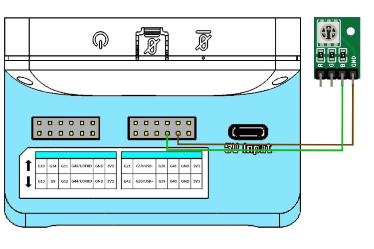
Circuit Diagram and Connections
The circuit connection is straightforward. We connect an external LED to GPIO 40 of the ESP32-S3-BOX-3 board through a current-limiting resistor. For the ease of demonstration, we have used the RGB LED module that came with the ESP32-S3-BOX-3. We will be using the DOCK accessory to connect the LED. Insert the ESP32S3-Box-3 into the dock. Connect the GND pin of the RGB Module to any of the ground points in the dock and any one of the anode pins to the G40 port in the dock. As already mentioned, if you are using a single external LED, connect the cathode of the LED to ground and the anode to the G40 through a current-limiting resistor. The image below shows the connection.
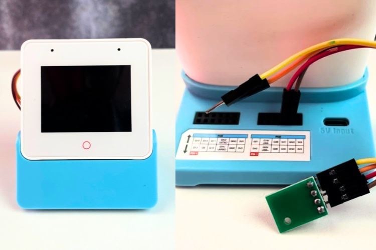
Here is the ESP32S3-Box-3 with the LED attached.
Project Setup Beginner's Guide
ESP-IDF Installation
This project requires ESP-IDF v5.5.2. For full installation and configuration instructions, refer to the official Espressif Getting Started Guide:
ESP-IDF Getting Started Guide (Official)
Then make sure to get our project file from our repo using git clone or manually downloading and extracting it to your preferred location.
git clone https://github.com/Circuit-Digest/Voice-Activated-LED-Controller-with-Touch-Interface-Using-ESP32S3-Box-3Project Configuration
1. Set up the ESP-IDF environment: Once you have properly installed and set up the ESP-IDF following Espressif's guide, on Mac or Linux systems, open a terminal and run the following command to set up the ESP-IDF environment. Make sure not to close the terminal once done, and any upcoming idf command has to be executed through the same terminal or command prompt. If you ever close the terminal, or when opening the project later, run this command first to set up the environment. This has to be done in each new section.
. $HOME/esp/esp-idf/export.shOn Windows PCs, you can directly run the ESP-IDF command prompt shortcut in the Start menu, created by the ESP-IDF installer.
2. Navigate to the project directory. The path you provide must be to the root folder of your project directory.
cd /path_to_your_project_directory3. Configure the project: The menu config option is used to change or reconfigure the project parameters. It is completely optional since all required properties are already configured. But if you need, you can use the following command to access the menuconfig options.
idf.py menuconfig4. Build the project: You can use the following script to build the project. When it's executed, the IDF will copy any required managed components to the project folder and build the project. If any error occurs, other than related to code, it is highly recommended to do a full clean and then build.
idf.py build5. Flash and monitor: the following command is used to flash the code to the ESp32S3-Box-3 and monitor the serial log. Make sure to connect the board to the computer before running the command. If the board is not detected, even after connecting to the computer, Press and hold the boot button and then press the reset button. Later, release the boot button and try to upload the code. Once uploaded with this method, make sure to reset the board manually once the code is uploaded.
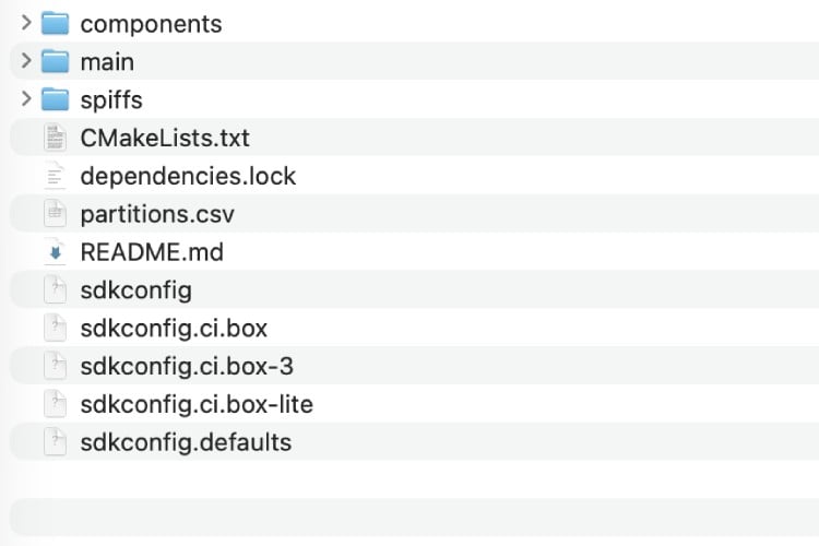
idf.py flash monitorProject Structure Overview
For your reference, this is the file structure of our project. The Main folder contains all the source code, while the components folder contains unmanaged component libraries, and the spiffs folder contains all the image or audio files.
How Wake Word Detection Works
Wake word detection uses ESP-SR WakeNet, a low-power neural network engine that runs continuously in the background. The Audio Front-End (AFE), preprocesses audio from the microphone array. Sample rate: 16 kHz, 16-bit signed, 2 channels (stereo). Then the WakeNet Engine does the CNN-based wake word detection. The Wakenet framework continuously monitors the audio stream with low power consumption. It supports up to 5 wake words simultaneously. The wake word detection flow is as given below.
Microphone -> I2S -> AFE -> WakeNet -> Wake Detection Event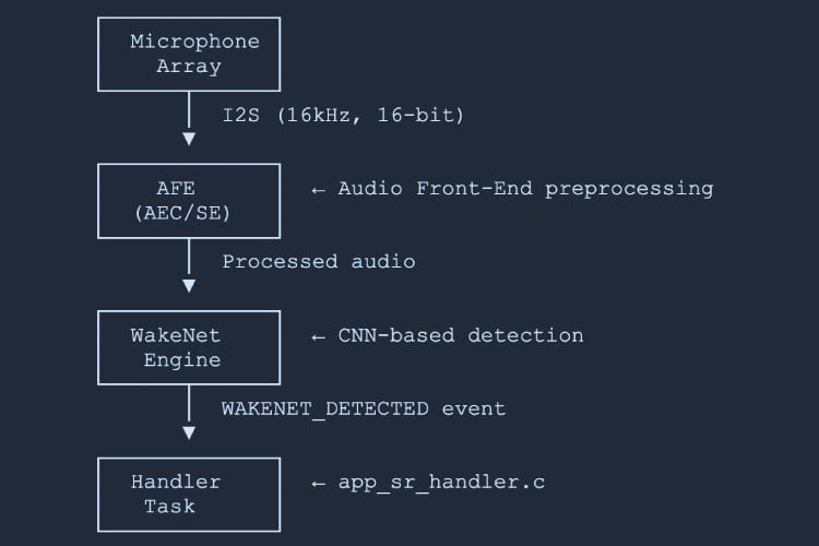
Detection Events
- WAKENET_DETECTED - Wake word detected; start listening for commands.
- WAKENET_CHANNEL_VERIFIED - Channel verified; ready for command recognition.
The following key functions are used for the wakeword detection and are called from main/app/app_sr.c.
- audio_feed_task() - Reads audio from I2S and feeds it to AFE
- audio_detect_task() - Processes AFE output and detects wake words
- app_sr_start() - Initialises AFE and WakeNet models
Available Wake Words
The project supports multiple pre-trained wake words. Configure them via idf.py menuconfig.
Navigation: idf.py menuconfig -> ESP Speech Recognition -> Load Multiple Wake Words
| Wake Word | Language | Config Key |
| Hi ESP | English | |
| Hi Lexin | Chinese | |
| Alexa | English | |
| Xiao Ai Tong Xue | Chinese | |
| Ni Hao Xiao Zhi | Chinese | |
How to Change Wake Words
Method 1 - Using menuconfig
1.Run idf.py menuconfig
2.Navigate to: ESP Speech Recognition -> Load Multiple Wake Words
3.Enable or disable desired wake words.
4.Save and rebuild: idf.py build flash
Method 2 - Modify Code
Wake word selection happens in app_sr.c:
// In app_sr_set_language() function (line ~235)
char *wn_name = esp_srmodel_filter(models, ESP_WN_PREFIX,
   (SR_LANG_EN == g_sr_data->lang ? "hiesp" : "hilexin"));
To switch the English wake word to "Alexa":
char *wn_name = esp_srmodel_filter(models, ESP_WN_PREFIX,
   (SR_LANG_EN == g_sr_data->lang ? "alexa" : "hilexin"));
Using Custom Wake Words
Requirements: A custom wake word model trained with ESP-SR tools, in ESP-SR compatible format, with sufficient model partition space.
1. Train a custom wake word using ESP-SR training tools (see ESP-SR documentation).
2. Place the generated model file (.bin) in spiffs/ or the model partition.
3. Enable the custom word in menuconfig: For eg, ESP Speech Recognition -> CONFIG_SR_WN_WN9_CUSTOMWORD
4 .Update code in app_sr.c:
char *wn_name = esp_srmodel_filter(models, ESP_WN_PREFIX, "customword");5. Rebuild and flash: idf.py build flash
How Speech Recognition Works
Speech recognition uses ESP-SR MultiNet, an offline command recognition engine that supports up to 200 commands without requiring cloud connectivity. Both English and Chinese are supported in the ESP-SR engine.
Wake Word Detected -> AFE Processing -> MultiNet -> Command ID -> Handler Action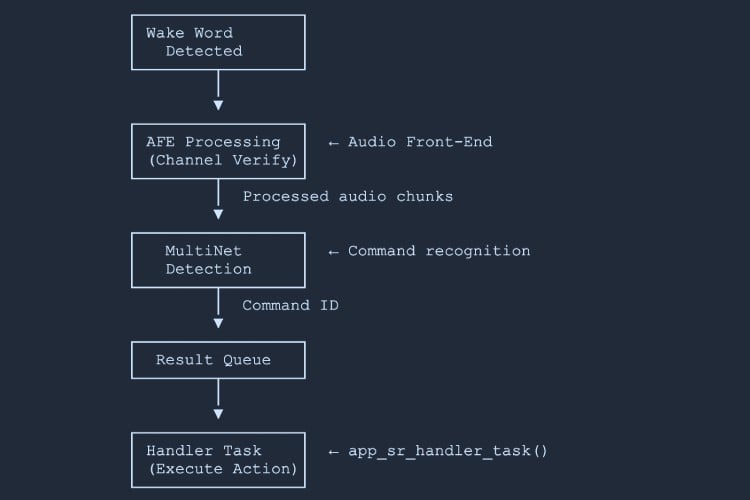
Recognition States
- ESP_MN_STATE_DETECTING - Listening for a command
- ESP_MN_STATE_DETECTED - Command recognised
- ESP_MN_STATE_TIMEOUT - No command detected within timeout
Key Components
- Command Definition (app_sr.c) - defines the text and phoneme for each command
- Command Structure (app_sr.h) - struct holding cmd ID, language, text, and phoneme
- Recognition Process (audio_detect_task) - AFE processes audio, MultiNet analyses chunks, returns command ID via queue to handler
// Command definition array  (app_sr.c)
static const sr_cmd_t g_default_cmd_info[] = {
   {SR_CMD_LIGHT_ON,  SR_LANG_EN, 0, "turn on light",  "TkN nN LiT", {NULL}},
   {SR_CMD_LIGHT_OFF, SR_LANG_EN, 0, "turn off light", "TkN eF LiT", {NULL}},
};
How to Modify Commands
⇒ Step 1 - Add Command Enum (app_sr.h)
typedef enum {
   SR_CMD_LIGHT_ON,
   SR_CMD_LIGHT_OFF,
   SR_CMD_MY_NEW_CMD,    //  Add your command enum
   SR_CMD_MAX,
} sr_user_cmd_t;
⇒ Step 2 - Add Command Definition (app_sr.c)
static const sr_cmd_t g_default_cmd_info[] = {
   {SR_CMD_LIGHT_ON,     SR_LANG_EN, 0, "turn on light",  "TkN nN LiT", {NULL}},
   {SR_CMD_LIGHT_OFF,    SR_LANG_EN, 0, "turn off light", "TkN eF LiT", {NULL}},
   {SR_CMD_MY_NEW_CMD,   SR_LANG_EN, 2, "my new command", "mI nU kMnd", {NULL}},  //   Add
};
⇒ Step 3 - Add Handler Action (app_sr_handler.c)
case SR_CMD_MY_NEW_CMD:        //   Add your handler
   ESP_LOGI(TAG, "My new command executed!");
   // Your action here
   break;
⇒ Step 4 - Rebuild and Flash
idf.py build flash monitorAdding Multiple Commands
// app_sr.h - enum
SR_CMD_FAN_ON,
SR_CMD_FAN_OFF,
SR_CMD_SET_BRIGHTNESS_HIGH,
SR_CMD_SET_BRIGHTNESS_LOW,
// app_sr.c - command definitions
{SR_CMD_FAN_ON,                  SR_LANG_EN, 2, "turn on fan",      "TkN nN fN",    {NULL}},
{SR_CMD_FAN_OFF,                 SR_LANG_EN, 3, "turn off fan",     "TkN eF fN",    {NULL}},
{SR_CMD_SET_BRIGHTNESS_HIGH,     SR_LANG_EN, 4, "brightness high",  "brItns hI",    {NULL}},
{SR_CMD_SET_BRIGHTNESS_LOW,      SR_LANG_EN, 5, "brightness low",   "brItns lO",    {NULL}},
Dynamic Command Addition (Runtime)
sr_cmd_t new_cmd = {
   .cmd     = SR_CMD_MY_NEW_CMD,
   .lang    = SR_LANG_EN,
   .id      = 10,
   .str     = "my command",
   .phoneme = "mI kMnd"
};
app_sr_add_cmd(&new_cmd);
app_sr_update_cmds();   // Update MultiNet command list
API Functions (app_sr.h)
- app_sr_add_cmd() - Add a new command
- app_sr_modify_cmd() - Modify an existing command
- app_sr_remove_cmd() - Remove a command
- app_sr_remove_all_cmd() - Clear all commands
- app_sr_update_cmds() - Update MultiNet with the current command list
How Display and Touch Work
The project uses LVGL (Light and Versatile Graphics Library) for GUI rendering and touch input.
- Display Driver - ILI9341 LCD controller (320×240), SPI interface, RGB565 colour format, hardware-accelerated rendering.
- Touch Driver - GT911 capacitive touch controller via I2C, with multi-touch support (single touch used in this project).
- LVGL Integration - LVGL runs in a dedicated task with double buffering for smooth rendering. Touch events are handled via the LVGL input driver.
Initialisation (main.c)
bsp_display_cfg_t cfg = {
   .lvgl_port_cfg  = ESP_LVGL_PORT_INIT_CONFIG(),
   .buffer_size    = BSP_LCD_H_RES * CONFIG_BSP_LCD_DRAW_BUF_HEIGHT,
   .double_buffer  = 0,
   .flags          = { .buff_dma = true }
};
bsp_display_start_with_config(&cfg);
bsp_board_init();
Creating GUI Elements
#include "lvgl.h"
#include "bsp/esp-bsp.h"
bsp_display_lock(0);            // Lock for thread safety
lv_obj_t *scr  = lv_scr_act();  // Get current screen
// Create a button
lv_obj_t *btn  = lv_btn_create(scr);
lv_obj_set_size(btn, 100, 50);
lv_obj_align(btn, LV_ALIGN_CENTER, 0, 0);
// Add label
lv_obj_t *label = lv_label_create(btn);
lv_label_set_text(label, "Click Me");
// Add click callback
lv_obj_add_event_cb(btn, on_button_click, LV_EVENT_CLICKED, NULL);
bsp_display_unlock();
Touch Event Handling
static void on_touch_event(lv_event_t *e)
{
   lv_event_code_t code = lv_event_get_code(e);
   lv_obj_t       *obj  = lv_event_get_target(e);
   switch (code) {
   case LV_EVENT_PRESSED:
       lv_obj_set_style_bg_color(obj, lv_color_hex(0x0000FF), 0);
       break;
   case LV_EVENT_RELEASED:
       lv_obj_set_style_bg_color(obj, lv_color_hex(0x00FF00), 0);
       break;
   case LV_EVENT_CLICKED:
       light_ctrl_toggle();   // Perform action
       break;
   default: break;
   }
}
Supported Event Types
- LV_EVENT_CLICKED - Touch released after press
- LV_EVENT_PRESSED - Touch pressed
- LV_EVENT_RELEASED - Touch released
- LV_EVENT_LONG_PRESSED - Long press detected
Using Images in the GUI
The project converts BMP from images stored in an array using the image_to_c tool by bitbank2, to LVGL-compatible RGB565 format at runtime using bmp_to_lv_img() in light_ui.c. If you wan you can also use the LVGL image converter tool to convert the images to c array. One other option is to store the image files in the file system and load them from there.
lv_img_set_src(img_obj, "/spiffs/image.bin");Creating Custom GUI Screens
Here is an example code snippet showing how to create a new screen for the GUI. The LV object creation macro is used to create or define each screen.
// Screen 1: Main
lv_obj_t *main_screen = lv_obj_create(NULL);
// ... add widgets ...
// Screen 2: Settings
lv_obj_t *settings_screen = lv_obj_create(NULL);
// ... add widgets ...
// Navigate
void goto_settings(lv_event_t *e) { lv_scr_load(settings_screen); }
void goto_main(lv_event_t *e)     { lv_scr_load(main_screen);     }
Warning: Each RGB565 pixel = 2 bytes. A 320×240 screen buffer = ~150 KB. Double buffering doubles that. Consider using PSRAM for large buffers.
For more details on how to use the LVGL library, please check out the official LVGL documentation.
How Audio Output Works
Audio output uses the I2S interface with an ES8311 codec chip for digital-to-analog conversion. The I2S Driver handles audio data transfer. Sample rate: 16 kHz default for SR feedback, 16-bit, stereo (2 channels). The ES8311 codec with I2S input provides analog output to the speaker and volume and mute control.
Audio Playback Flow
WAV File -> Memory Buffer -> I2S Write -> Codec -> SpeakerKey Functions (app_sr_handler.c)
- sr_echo_init() - Loads WAV files from SPIFFS to memory
- sr_echo_play() - Plays an audio segment via I2S
- bsp_i2s_write() - Writes audio data to I2S (BSP function)
Audio Playback Implementation
typedef enum {
   AUDIO_WAKE,   // Wake word detected tone
   AUDIO_OK,     // Command recognised tone
   AUDIO_END,    // Timeout / end tone
   AUDIO_MAX,
} audio_segment_t;
// Load WAV from SPIFFS  -> PSRAM
static esp_err_t load_wav_to_mem(audio_segment_t seg, const char *path)
{
   FILE *fp = fopen(path, "rb");
   if (!fp) return ESP_ERR_NOT_FOUND;
   fseek(fp, 0, SEEK_END);
   long sz = ftell(fp);
   fseek(fp, 0, SEEK_SET);
   s_audio[seg].buf = heap_caps_malloc(sz, MALLOC_CAP_SPIRAM | MALLOC_CAP_8BIT);
   s_audio[seg].len = (size_t)sz;
   fread(s_audio[seg].buf, 1, sz, fp);
   fclose(fp);
   return ESP_OK;
}
Adding More Audio Playbacks
⇒ Step 1 - Add Audio Segment Enum
typedef enum {
   AUDIO_WAKE,
   AUDIO_OK,
   AUDIO_END,
   AUDIO_CUSTOM_1,   //   Add your segment
   AUDIO_CUSTOM_2,
   AUDIO_MAX,
} audio_segment_t;
⇒ Step 2 - Add WAV File to SPIFFS
Place your WAV file in the spiffs/ directory. WAV requirements: uncompressed PCM, 16 kHz recommended, 16-bit, mono or stereo.
spiffs/
├── echo_en_wake.wav
├── echo_en_ok.wav
├── echo_en_end.wav
├── custom_sound_1.wav     Add here
└── custom_sound_2.wav
⇒ Step 3 - Load in Initialisation
ESP_RETURN_ON_ERROR(
   load_wav_to_mem(AUDIO_CUSTOM_1, "/spiffs/custom_sound_1.wav"),
   TAG, "load custom1 wav failed");
⇒ Step 4 - Play When Needed
sr_echo_play(AUDIO_CUSTOM_1);⇒ Step 5 - Rebuild
idf.py build flashThe SPIFFS partition is automatically rebuilt with files from the spiffs/ directory.
Audio Format Requirements
| Parameter | Value |
| Sample Rates | 8, 16, 22.05, 44.1, 48 kHz |
| Bit Depth | 16-bit (recommended) |
| Channels | Mono or Stereo |
| Format | Uncompressed PCM WAV |
Converting Audio with FFmpeg
# Convert to 16 kHz, 16-bit, mono WAV
ffmpeg -i input.mp3 -ar 16000 -acodec pcm_s16le -ac 1 output.wav
# Convert to 16 kHz, 16-bit, stereo WAV
ffmpeg -i input.mp3 -ar 16000 -acodec pcm_s16le -ac 2 output.wav
BSP Audio API Reference
The following BSP functions (bsp_board.h) control the audio codec:
| Function | Description |
| Set codec sample rate, bit depth, and channel mode |
| Set volume level (0-100) |
| Mute or unmute the audio codec |
| Write audio data buffer to I2S output |
| Stop the codec device |
| Resume the codec device |
Memory Considerations
- 16 kHz, 16-bit, mono -> ~32 KB per second
- 16 kHz, 16-bit, stereo -> ~64 KB per second
- 44.1 kHz, 16-bit, stereo -> ~176 KB per second
Recommendations
- Use PSRAM for audio buffers (MALLOC_CAP_SPIRAM)
- Pre-load frequently used sounds into memory
- Stream long audio files from SPIFFS in 4 KB chunks
Streaming Long Audio
void play_long_audio_stream(const char *wav_path)
{
   FILE *fp = fopen(wav_path, "rb");
   if (!fp) return;
   fseek(fp, 44, SEEK_SET);     // Skip WAV header
   uint8_t chunk[4096];
   size_t  bytes_read;
   while ((bytes_read = fread(chunk, 1, sizeof(chunk), fp)) > 0) {
       size_t bytes_written = 0;
       bsp_i2s_write((char *)chunk, bytes_read, &bytes_written, portMAX_DELAY);
   }
   fclose(fp);
}
Changing the LED Pin
1. Open the file: main/app/app_led.c
2. Find this line (around line 15):
#define SINGLE_LED_GPIO GPIO_NUM_403. Change it to a different pin (e.g. GPIO 38):
#define SINGLE_LED_GPIO GPIO_NUM_384. Save the file.
5. Rebuild and flash:
idf.py build flash monitor6. Test: Connect your LED to GPIO 38 instead of GPIO 40.
Building & Flashing
Once the hardware is connected and the software is set up, follow these steps to compile and upload the code.
⇒ Step 1 - Navigate to the Project Directory
cd /path/to/esp32-box3-voice-led-project⇒ Step 2 - Activate ESP-IDF Environment
. $HOME/esp/esp-idf/export.sh⇒ Step 3 - Configure (Optional)
idf.py menuconfig⇒ Step 4 - Build
idf.py buildThis compiles all source files and creates the firmware binary. The first build may take several minutes as dependencies are downloaded.
⇒ Step 5 - Flash and Monitor
idf.py flash monitor*Tip: Press Ctrl+] to exit the serial monitor.
Final Result
After successfully flashing the firmware, the ESP32-S3-BOX-3 boots and displays the light control screen. Now we can control the LED with two different methods.
The first method is to use the voice commands. To use it:
1. Say the wake word: "Hi ESP" (speak clearly, about 1 metre from the device).
2. Wait for audio feedback - you'll hear a confirmation sound.
3. Speak the command: "Turn on light" or "Turn off light".
4. Observe: the LED changes state, the screen updates, and audio feedback plays.
5. Once the wake word is detected, you can continuously give commands without using the wake word. If you haven't provided any commands for a certain time(a few seconds), the ESP-SR engine will time out. To use it again, all you have to do is say the wake word again to trigger the wake word detection.
The second method is to use the touch screen. For that:
1. Touch the on-screen toggle button.
2. Observe: the LED toggles and the button image changes.
Here is the final result:
Troubleshooting
Wake Word Not Detected
- Speak louder and clearer, at 0.5-1 metre from the device.
- Reduce background noise.
- Check the serial monitor for AFE initialisation errors.
LED Doesn't Light Up
- Verify LED polarity
- Verify the GPIO 40 connection.
- Test with a multimeter: GPIO should read 3.3 V when ON.
Build Errors
- Ensure ESP-IDF v5.5.2 is correctly installed.
- Run . $HOME/esp/esp-idf/export.sh before building.
- Do a full clean rebuild: idf.py fullclean && idf.py build.
Touch Screen Not Responding
- Check the serial monitor for LVGL initialisation messages.
No Audio Feedback
- Ensure WAV files are in the spiffs/ directory before building.
- Check speaker volume (may need physical adjustment).
- Verify I2S initialisation in serial logs.
GitHub Link
Find the project’s codebase and documentation here. Explore, fork, and contribute on GitHub.


