

Every electronic system or device needs electric power to operate, whether it is from your walled AC supply or a battery. This electric power cannot be stored infinitely in any rechargeable device like batteries, condensers or Supercapacitors. So any portable devices like laptops or mobile phones are needed to be connected to AC power lines to recharge their batteries regularly.
Typically electric cables are used to connect these rechargeable devices like smartphones, tablets, earphones, Bluetooth speakers, etc to AC-DC adapters. Using electronic conductor cables to transfer power or data between two systems is the most basic and popular way since the discovery of electricity itself. And people are happy using electric cables up until now but with the advancement of technology, human safety and mankind hunger for perfection in beauty leads to the concepts of Wireless power transfer (WPT) or wireless energy transmission (WET) into picture which is long lost in history. In some of our previous articles, we have explained Wireless power Transmission in detail and also built a circuit to wireless transfer the Power to glow an LED.
The first considerable experimental application for Wireless power transfer (WPT) was done in the early 1890s by inventor Nikola Tesla. During the experiments, electric power is transmitted by inductive and capacitive coupling using spark-excited radio frequency resonant transformers, now called Tesla coils. Though these experiments are partially successful, they are not efficient and require high investment. So, later on, these experiments are scrapped and the technology study was stagnated for many years layer. We have also built a mini tesla coil to demonstrate the concept of Tesla coils.
Although even now there is no effective way to deliver high power wirelessly, it is possible to design a circuit with the present technologic advancements to transfer low power between two systems effectively. And the wireless chargers are designed based on this newly developed circuit which enables it to deliver power to smartphones and other small electronic devices wirelessly.
Various Wireless Charging Technology used in Wireless Charger
Ever since the concept of wireless power transfer became popular both scientists and engineers came up with various ways to realize this concept. Although most of these experiments led to failures or unpractical results, few of these experiments did produce satisfactory results. These tested and working ways for achieving wireless power transfer have their own advantages, disadvantages, and features. Among these various methods, only a couple are used in designing Wireless Chargers. Whiles other methods have their own application area and advantages.
Now for better understanding, these methods are classified based on the distance of transmission, maximum power, and method used to achieve power transmission. In the below figure we can see various ways used for achieving wireless power transfer technology and their classification.
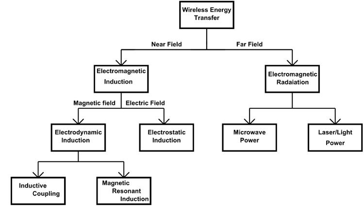
Here,
- The first and most important classification is based on how far power transfer is possible. In the experimented methods, some are capable of delivering power wirelessly to loads at large distance away while others could only deliver power to loads only a few centimeters away from the source. So the first division is based on whether the method is of Near Field or Far Field.
- The difference in distance capability comes based on the type of phenomenon used by various methods to achieve wireless power transfer. For example, if the medium used by the method to deliver power is Electro-Magnetic Induction then the maximum distance can be no higher than 5cm. This is because the loss of magnetic flux increases exponentially with an increase in distance between source and load which leads to unacceptable power losses. On the other hand, if the medium used by the method to deliver power is Electro Magnetic Radiation then the maximum distance can go as high a few meters. This is because EMR can be concentrated to a focal point which is at meters away from the source. Also, methods that use EMR as a medium to deliver power have higher efficiency when compared with others.
- In the many ways mentioned above, some are more popular than others and the popular methods used widely are discussed below.
There are two popular methods for wireless power transmission which use Electro Magnetic Radiation as a medium- Microwave Power and Laser/light Power
Microwave Wireless Power Transfer
As the name itself gives it away in this method it will use the Microwave spectrum of EMR to deliver power to load. First, the transmitter will draw power from an outlet or any other stable power source and then regulate this AC power to the required level. After that, the transmitted power will generate microwaves by consuming this regulated power supply. The microwaves travel through air without any interruption to reach the receiver or load. The Receiver will be equipped with appropriate devices to receive this microwave radiation and converting it into electrical energy. This converted electric power is directly proportional to the amount of microwave radiation reached to the receiver and hence wireless power transfer using Microwave radiation is achieved.

Laser Light Wireless Power Transfer
Any person who deals with electronics and electric power should have come across a concept called solar power generation. And if you remember correctly the concept of solar power generation is nothing but using Electromagnetic Radiation of sun to generated electricity. This conversion process can be based on systems of solar panels, solar heating or any other and a solar power charger can be easily build using solar panels. But the key issue here is the energy transferred by the sun to the earth is in the form of Electro Magnetic Radiation and is specifically in the visible spectrum and the transfer of energy here done wirelessly. Hence the concept of solar power generation is itself a mega Wireless Power Transmission System.
Now, if we replace the sun with a smaller EMR generator (or simply a light source) then we can focus the radiation generated on to a load which is hundreds of meters away from the light source. Once this focused light reaches the solar panel of the receiver module (or load), it converts the light energy into electric power which is the original goal of wireless power transmission setup.
Up until now, we discussed techniques or methods that are capable of delivering power to load which are few meters away from the source. Although these techniques have distance capability, they are bulky and costly so they are not suitable for Mobile Charger design. The most practical methods that can be used for the design of wireless chargers are namely ‘Inductive Coupling Type’ and ‘Magnetic Resonant Induction’. These are the two methods that use the Faradays Law of Electromagnetic Induction as the principle and Magnetic flux as propagating phenomenon to achieve wireless power transmission.
Wireless Power Transmission using Inductive Coupling
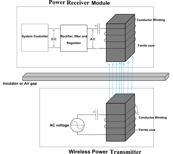
The setup used in Inductive coupling is very similar to the one used for Electrical Transformer. For better understanding, let us look into the typical application circuit of the Inductive Coupling Wireless Power Transfer method.
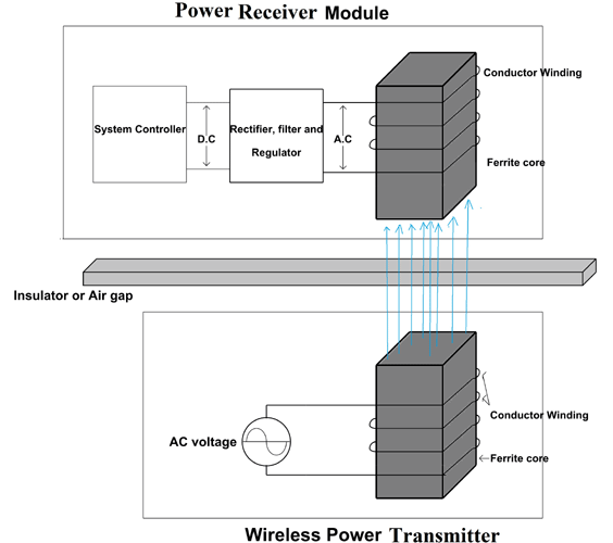
- In the above functional diagram, we have two sections one is an electric power transmission setup, and the other is the electric power receiver setup.
- Both sections are electrically isolated with each other and are separated by an insulator of a couple of centimeter width. Though both sections do not have any electrical interaction still there is a magnetic coupling between them.
- The AC voltage source present in the transmitter module provides power to the entire system.
Working of Inductive Coupling type Wireless Transmission: From the beginning, a current flow in the conductor coil is present in the Transmitter module because an AC voltage source is connected to the end terminals of the coil. And because of this current flow, a magnetic field should be generated around the conductors of the coil which is tightly wound around a ferrite core. Because of the presence of a medium, all the magnetic flux of the coil gets concentrated on the ferrite core. This flux moves along the axis of the ferrite core and gets ejected into the free space outside the transmission module as shown in the figure.
Now, if we bring the receiver module near the transmitter, then the magnetic flux emitted by the transmitter will cut the coil present in the receiver module. Since flux generated by the transmitter module is varying flux, then an EMF must be induced into the conductor brought in its range according to Faradays Law of Electromagnetic Induction. Based on this theory an EMF must also be inducted into the receiver coil which is experiencing the magnetic flux generated by the transmitter. This generated voltage will be rectified, filtered, and regulated to get a proper DC voltage which is very much needed for the system controller.
In some cases, ferrite core is also eliminated to make the transmitter and receiver more compact and light. You can see this application in Wireless mobile phone charger and Smartphone pair. As we all know industries at present competing neck to neck to release high-performance smartphones and other devices that are lighter, slimmer, and cooler. The designers are literally having nightmares to achieve these features without compromising the performance, so making the device bulky just for the sake of wireless power transmission is unacceptable. So the designers and engineering coming up with more slimmer and lighter modules that can be fitted into smartphones and tablets.
Here you can see the internal construction of the latest wireless charger.
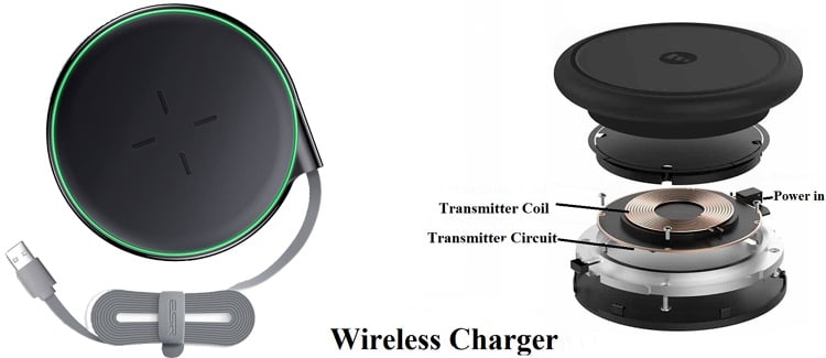
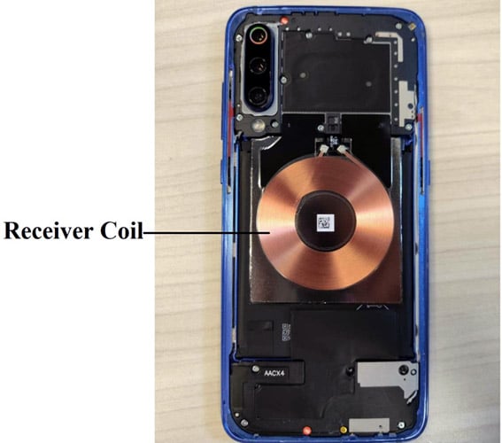
The Smartphone with the wireless power capability will also have a similar coil to make the electromagnetic induction possible. You can see in the below figure, how the slim coil is attached at the bottom end of the Smartphone near to the battery. You can see how engineers designed this wireless charger so slim without compromising in its performance. The working of this setup is similar to the case discussed above except that it’s not having any ferrite core at the center of the winding.
Although this way of transmitting power through Electromagnetic Induction seems easy but it’s not comparable to an efficient method of delivering power through the cable.
Magnetic Resonant Induction based Wireless Power Transfer
Magnetic Resonant Induction is a form of inductive coupling in which power is transferred by magnetic fields between two resonant circuits (tuned circuits), one in the transmitter and one in the receiver. Because of this, the setup of the Magnetic Resonant Induction circuit must be very similar to the Inductive Coupling circuit which we discussed previously.
You can see in this figure except for the presence of series capacitors the entire circuit is similar to the previous case.
Working: The working of this model is also very similar to the previous case except here the circuits present in transmitter and receiver are tuned to operate at the resonant frequency. The capacitors are specially connected in series with both the coils to achieve this resonant effect.
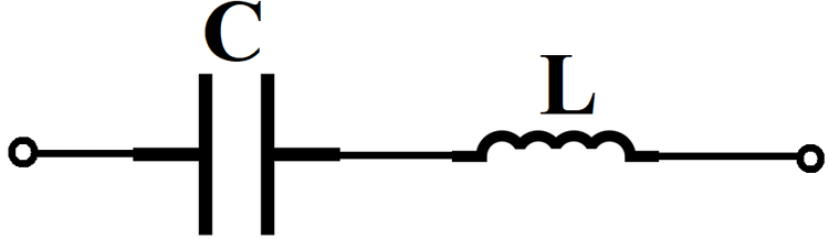
As we all know a capacitor in series with an inductor will form a series L-C circuit as shown in the figure. And the value of frequency at which this circuit will operate at resonance can be given as,
Fr = 1 / 2ᴫ(LC)1/2
Here L = Inductor value and C = Capacitor value.
By using the same formula we will calculate the value of resonant frequency for the power transmitter circuit and adjust the AC power source frequency to that calculated value.
Once the source frequency is adjusted then the transmitter circuit along with the receiver circuit will operate at the resonant frequency. After this, an EMF must be induced in the receiver circuit according to the Faradays Law of Induction as we discussed in the previous case. And this induced EMF will be rectified, filtered and regulated to get a proper DC voltage as shown in the figure.
Up until now, we discussed various techniques that can be used for wireless power transmission along with their typical application circuits. And we use these methods to develop circuits for all the wireless power transmission systems like wireless charger, wireless electric vehicle charging system, wireless power transfer for drones, planes, etc.
Wireless Power Transfer Standards
Now with each company developing its own productions and charging stations, there is a need for common standards among all developers in order to make the consumer choose the best among the ocean of choices. So a couple of standards are followed by all industries that are working on developing wireless power transmission systems.
Various standards used to developing wireless power transfer devices like wireless charger:
‘Qi’ standards – by Wireless Power Consortium:
- Technology - Inductive, Resonant - Low Frequency
- Low power - 5W, Medium Power - 15W, Qi Cordless kitchen appliances from 100W to 2.4kW
- Frequency range - 110 – 205 kHz
- Products - 500+ products and used in more than 60 cellular phone companies
‘PMA’ standards – by Power Matter Alliance:
- Technology - Inductive, Resonant - High Frequency
- Power Out Max from 3.5W to 50W
- Frequency range - 277 – 357 kHz
- Products – only 2 but 1,00,000 power mats units are distributed globally
Advantages of Wireless Charger
- The wireless charger is very useful for charging home-based devices like a smartphone, laptop, iPod, notebook, earphone, etc,
- It provides a convenient, safe and effective way to transfer power without any medium.
- Environmental friendly - Doesn’t harm or injure a human or any living being.
- It can be used to charge medical implants which results in an improvement in the quality of life and reduces the risk of infection.
- No need for usual worry about the wear and tear of the power jack.
- Fumbling over power cable orientation is over with the use of wireless chargers.
Disadvantages of Wireless Charger
- Less efficiency and more power loss.
- Costs more than the cable charger.
- Repairing on the fault is difficult.
- Not suitable for high power delivery.
- Energy losses increase with load.
