
Ever wondered how does a motor spin? What are the fundamentals involved? How is it controlled? The DC brushed motors have been in the market since a long time and they spin easily on just a DC supply/battery whereas the induction motors and permanent magnet synchronous motors involve complex electronics and control theory to rotate them efficiently. Before we even get to what is a DC motor or what are other types of motors, it is important to understand the operation of linear motor – the most basic motor. This will help us understand the fundamentals behind a motor spinning.
I am a Power Electronics and Motor Control Engineer and the next blog would be on motor control. But there are certain topics which are necessary to understand before going into the depth of motor control and we will cover them in this article.
- Operation of a Linear Motor
- Types of Motors and its History
- Saliency
- Flux Interaction between the Stator and Rotor
Operation of a Linear Motor
Being a power electronics engineer, I did not know much about the operation of motors. I read many notes, books and referred videos. I had a hard time understanding some of the motors and its control in depth until I referred again to the basic electro-mechanical energy conversion laws – Faraday and Lorentz Force Laws. We will spend some time understanding these laws. Some of you might already know it but it is good to go through them once again. You might learn something new.
Faraday’s law
Faraday’s Law of Induction states the relationship between the flux of a coil of wire and the voltage induced in it.
e(t) = -dφ/dt …(1)
Where Φ represents the flux in the coil. This is one of the fundamental equations used to derive the electrical model of a motor. This situation does not happen in practical motors as the coil would consist of a number of turns, distributed in space and we would have to account for the flux through each of these turns. The term flux linkage (λ) represents the total flux linked with all the coils and it is given by the following equation
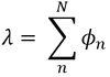
Φn represents the flux linked with nth coil and N is the number of turns. It can be described as the coil is formed of N single turns in a series configuration. Thus,
λ = Nφ
e(t) = -dλ/dt = -Ndφ/dt
The minus sign is usually attributed to Lenz’s law.
Lenz’s law states the following: An EMF (electromotive force) is induced in a coil of wire if the flux linked with it changes. The polarity of the EMF is such that if a resistor was shunted across it, the current flowing in it would oppose the change in flux which induced that EMF.

Let us understand the Lenz Law through a conductor (rod) placed in a magnetic field (B̅) pointing downwards into the plane of the paper as shown above figure. A force Fapplied moves the rod horizontally but the rod is always in contact with the horizontal conductors. The external resistor R is used as a shunt to allow the current to flow. So, the arrangement acts like a simple electrical circuit with a voltage source (the induced EMF) and a resistor. The flux linked with this loop is changing as the area linked with the B̅ is increasing. This induces an EMF in the circuit according to the Faraday’s Law (the magnitude is decided by how fast the flux is changing) and Lenz’s Law (the polarity is decided such that the current induced will oppose the change of flux).
Right Hand Thumb Rule will help us in knowing the direction of the current. If we curl our fingers in the direction of the induced current, then the thumb will give the direction of the generated field by that induced current. In this case, to oppose the increasing flux due to B̅ field, we need to develop a field a field out of the plane of the paper, and hence, the current will flow in a counter-clockwise direction. As a result, terminal A is more positive than the terminal B. From the load point of view, a positive EMF is developed with increasing flux and hence we will write the equation as
e(t) = d λ/dt
Observe that we have ignored the negative sign as we are writing this equation from the point of view of the load. (A similar case will come up when we start dealing with motors). The final electrical circuit will take the form as below figure. Even though the discussed case is of a generator, we have used the sign convention from the motor point of view and the polarity shown in the figure below is correct. (It will become obvious when we move on to the motor operation).

We can calculate the EMF induced as follows. A coil of 1 turn (conductor in this case) will produce a flux linkage of:
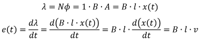
Where A represents the area of the loop, l is the length of the conductor, v is the velocity with which the rod is moving because of the applied force.
Looking at above Equation, we can say that the magnitude of EMF is proportional to the speed of the conductor and independent of the external resistor. But the external resistor will determine how much force is needed to maintain the velocity (and hence the current). This discussion is continued forward in the form of Lorentz Law.
Lorentz Law
We will check out the equation first and then try to understand it.
F = q . (E + Vc x B)
It states that when a particle of charge q moves with a velocity of vc in an electromagnetic field, it experiences a force. In a motor, the electric field E is irrelevant. Thus,
F = q . Vc . B
If the field is constant with time over the length of the conductor and perpendicular to it, we can write the above equations as:
F = q . dx/dt . B = dq/dt . x . B = i. l. B = B. i . l
It shows that the force acting on the charge is directly proportional to the current.
Back to first figure, we have seen that an external force applied induces an EMF which induces current in a resistor. All the energy is dissipated as heat in the resistor. The law of conservation of energy should be satisfied and hence we get:
F . v = e . i
This equation represents how mechanical energy is converted to electrical energy. This arrangement is called a linear generator.
We can finally check out how a motor runs i.e. how the electrical energy is converted to mechanical energy. In in below figure, we have replaced the external resistor with a lumped resistor of the circuit and now there is an external voltage source which supplies the current. In this case, we will observe a force developed (FDEVELOPED) given by the Lorentz Law. The direction of the force can be established by the Right-Hand Rule shown below


This is how a linear motor works. All the motors are derived from these basic principles. There are many detailed articles and videos that you will find describing the operation of brushed DC motor, brushless motors, PMSM motors, Induction motors, etc. So, it does not make sense making one more article describing the operation. Here is the link to some of the good educational videos on different types of motors and its operation.
History of Motors
- Historically, there have been three types of motors that have been widely used – brush commutator DC, synchronous and induction motors. Many applications demand varying speed and DC motors were widely used. But the introduction of thyristors around 1958 and the transistor technology changed the scene.
- Inverters were developed which helped in an efficient speed control application. The transistor devices could be turned on and off at will and it allowed PWM operation. The basic control schemes that were developed earlier were V/f drives for induction machines.
- In parallel, permanent magnets started replacing field coils to improve efficiency. And the use of inverter along with sinusoidal permanent magnet machines allowed elimination of brushes to improve the life and reliability of the motor.
- The next major step was in the control of these brushless machines. The two-reaction theory (or d-q theory) was introduced by Andre Blondel in France before 1900. It was combined with complex space vectors which allowed to model a machine accurately in transient and steady state. For the first time, the electrical and mechanical quantities could be related to each other.
- Induction motors did not see much changes until 1960. Two Germans – Blaschke and Hasse made some key innovations which led to the now famous vector control of induction motors. Vector control deals with the transient model of the induction motor rather than the steady state. Besides controlling the voltage amplitude to frequency ratio, it also controls the phase. This helped the induction motor to be used in speed control and servo applications with high dynamics.
- The sensorless algorithm was the next big step in control of these motors. Vector control (or Field Oriented Control) requires to know the rotor position. Expensive positions sensors were used earlier. The ability to estimate the rotor position based on the motor model allowed the motors to run without any sensors.
- There have been very few changes since then. The motor design and its control more or less remain the same.
Motors have been evolving since the last century. And electronics have helped them to be used in varying applications. The majority of electricity used in this world is consumed by motors!
Different Types of Motors
The motors can be classified in a lot of different ways. We will look at some of the classifications.

This is the most general classification. There has been a lot of confusion regarding AC and DC motors and it is important to make a distinction between them. Let us stick to the following convention: the motors that require an AC supply ‘at its terminals’ is called an AC motor and which can run on a DC supply ‘at its terminals’ is called a DC motor. ‘At its terminals’ is important because it eliminates what kind of electronics is used to run the motor. For example: The brushless DC motor actually cannot run directly on DC supply and it requires an electronic circuit.
The motor can be classified based on power supply and based on commutation - brush or brushless, as shown below


Though I am not going deep into the motor design of any of the above motors - There are two important topics that I would like to deal with - Saliency and Interaction of Rotor Flux with Stator Flux.
Saliency
Aspects of machine parameters like torque production and inductance are influenced by the magnetic structure of the machine (in permanent magnet machines). And the most basic of that aspect is the saliency. Saliency is the measure of change in reluctance with rotor position. As long as this reluctance is constant with every position of the rotor, the machine is called non-salient. If the reluctance changes with the rotor position, the machine is called salient.
Why saliency is important to understand? Because a salient motor can now have two methods to produce torque. We can take advantage of reluctance variation in the motor to produce reluctance torque together with the magnetic torque (produced by the magnets). As shown in below figure we can achieve higher torque levels for the same current with the addition of reluctance torque. This will be the case with IPM (Interior Permanent Magnet) motors. (There are motors that purely work on reluctance effect but we will not be discussing them here.) The next topic will help you to understand flux linkage and saliency much better.
(Note: Angle Advance in below figure refers to the phase difference between the stator current and air gap flux.)

Flux Interaction between the Rotor and the Stator
Flux in a motor travels from the rotor across the air gap to the stator and comes back again through the air gap back to the rotor to complete the field loop. In that path, the flux sees different reluctances (magnetic resistance). Laminations (steel) have a very low reluctance because of high μr (relative permeability of steel is in the range of thousands) whereas air gap has a very high reluctance (μr is approximately equal to 1).
The MMF (magnetomotive force) developed across the steel is very less as it has negligible reluctance compared to the air gap. (An analog to the electrical circuit would be: A voltage source (magnet) drives current (flux) through a resistor (air gap reluctance). The conductors (steel) connected to the resistor have very low resistance and we can ignore the voltage drop (MMF drop) across it). Thus the structure of the stator and rotor steel has a negligible influence and the entire MMF is developed across the effective air gap reluctance (any non-ferrous material in the flux path is considered to have a relative permeability equal to that of air-gap). The air gap length is negligible compared to the rotor diameter and it can be safely assumed that the flux from the rotor is perpendicular to the stator. There are fringing effects and other non-linearities due to slots and teeth but these are generally ignored in modeling the machine. (You CANNOT ignore them when designing the machine). But the flux in the air gap is not just given by the rotor flux (magnets in case of permanent magnet machine). The current in the stator coil also contributes to the flux. It is the interaction of these 2 fluxes that will determine the torque acting on the motor. And the term which describes it is called the effective air gap flux linkage. The idea is not to go into mathematics and derive the equations but to take away two points:
- We are concerned with only the flux in the air gap as the entire MMF is developed across it.
- The effective flux linkage in the air gap is due to both the stator current and rotor flux (magnets) and the interaction between them produces torque.

")
Above figure shows the rotor and stator of different types of motors. It would be interesting to find out which of them are salient and which are not?
Note: In each of these motors two axes are marked – D and Q. (Q-Axis is the magnetic axis and D-axis is electrically perpendicular to it). We will get back to the D and Q axis in future articles. It is not important for the above question.
Answer:
A,B,C – non-salient, D,E,F,G,H – salient (the magnets affect the reluctance in different rotor position, see below figure, in J,K- both the rotor and stator are non-salient.

We will end this article at this point. A lot more mathematics and machine modeling could have been discussed but it would become too complex here. We have covered most of the topics that are needed to understand the control of a motor. The next series of articles will directly move to Field Oriented Control (FOC), Space Vector Modulation (SVM), Flux Weakening, and all the practical hardware and software aspects where you might possibly get stuck once you start designing the controller.
Good Question!!
They are not detents, it is beacuse the rotor and the stator of the motor are locked. The most simple way to explain this would be through Law of conservation of Energy.
As you know a motor converts electrical energy to mechanical energy. Similarly all motor can acts as generator that could convert mechanical energy to electrical energy.
So when you are rotating the shaft of the motor you are making it act as a generator by producing electrocity on the terminals of the motor. The higher the power rating of the motor the harder it would be rotate the shaft. A technical answer would be, the rotor will be locked with stator (if stator has permanent magnets), also the rotor will be very heavy because of the weight of the coil and metal, so you have to put enough energy to rotate the rotor to make it cut through the magnetic flux with the coils in stator.

Hello Gents,
I worked at a company that rebuilt servo motors for cnc milling machines. Many were three phase AC motors. I ran across many that felt like they had "detents" in them as you manually turned their shaft, (similar to old stereo volume controls). Some were barely noticeable while others were so strong that you almost needed a pipe wrench to turn their shaft! There was nothing in them that interfered with their shaft rotating, i.e., no loose parts or debri. No one that I have ever asked could or would, (that being the manufacturer of the motor), tell me what caused this condition.
Can you help me understand this phenominum?
Thanks Tom