

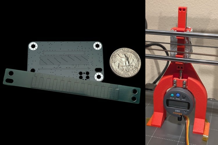
Cheap digital calipers hide a clever capacitive encoder inside, and Nick Steele (nichlock) has turned that idea into an open-source linear scale you can build yourself. It is just two PCBs, a sensor board with an STM32L4 and a passive copper "reflector" strip, sliding about 0.1 mm apart. The maker rates it at 40 µm accuracy against a Mitutoyo digital indicator, and the build costs roughly $32 before shipping.
How the PCB "sees" position
The sensor board has a grid of eight repeating transmit pads (the maker calls them emitters) and one long receive antenna. The reflector strip carries a row of T-shaped copper pads that couple four of the eight emitters into the receive antenna, and which four, and how strongly, depends on where the sensor sits along the strip. No part touches the other.
The STM32 steps its eight emitter pins through a fixed 16-state pattern at 16 kHz, so a full measurement completes at 1 kHz. Each time emitters switch, a small charge pulse reaches the receive antenna. A charge integrator turns that short pulse into a held step, an anti-alias filter cleans it up, and the ADC oversamples it over a long window for better SNR. All of that analog front end is inside the STM32L4 itself.
The firmware then "slides" the drive pattern across the emitters, gets a set of pulse sizes, and finds the zero crossing of the line through them to get a position inside one 5.08 mm period. Counting periods gives the full travel. The result goes out over UART at 460800 baud every millisecond, and a Python script plots it live.
Key specs
| Parameter | Value |
|---|---|
| Type | Incremental, capacitive |
| Accuracy rating | 40 µm (1.6 thou), against a Mitutoyo 543-793B-12 |
| Period | 5.08 mm (emitter pitch 0.635 mm) |
| Update rate | 1 kHz position output over UART |
| Gap | About 0.1 mm, set with two layers of Kapton tape |
| Licences | CERN-OHL-P-2.0 (hardware), MIT (firmware) |
Why it matters
Open, well-explained capacitive encoders are hard to find, which is exactly why the maker published this one. The README walks through the real problems: fringing fields at the pad edges, why a digital pin cannot keep stepping in one direction (he adds partial three-emitter transitions to get around it), and why a gap beats a bigger signal. The maker is also open about the limits. It is incremental, so it has to be zeroed at power-up. Liquids between the boards and thermal expansion over long lengths will hurt accuracy, and the first revision only managed about 0.5 mm. He is still working towards 10 µm, temperature compensation and absolute position sensing.
For anyone building a DIY DRO for a lathe or mill, a 3D printer axis check or a precision jig, it is a practical design to start from. KiCad files, firmware and test data are on GitHub.
Image credit: nichlock, from the open-linear-scale GitHub repository; composite of two photos, resized.
About the author: Aswinth Raj is an electronics engineer and the editor of CircuitDigest, where he has published more than 150 hands-on projects and tutorials across Arduino, PIC, ESP32, Raspberry Pi and EV battery systems. He selects the stories on this page for what engineers and makers can actually learn or build from. Connect on LinkedIn

Add a comment
No account needed. Your comment appears once a moderator has reviewed it.