
In our previous tutorials, we have learned about SPI and I2C communication between two Arduino boards. In this tutorial we will replace one Arduino board with the Blue Pill board that is STM32F103C8 and will communicate with the Arduino board using SPI bus. In this STM32 SPI Example, we will use Arduino UNO as Slave and STM32F103C8 as Master with Two 16X2 LCD display attached to each other separately. Two Potentiometers are also connected with STM32 (PA0) and Arduino (A0) to determine the sending values (0 to 255) from master to slave and slave to master by varying the potentiometer.
SPI in STM32F103C8
Comparing SPI bus in Arduino & STM32F103C8 Blue Pill board, STM32 has 2 SPI bus in it while Arduino Uno has one SPI bus. Arduino Uno has ATMEGA328 microcontroller in it, and STM32F103C8 has ARM Cortex- M3 which makes it faster than Arudino Board.
To learn more about SPI communication, refer our previous articles
STM32 SPI Pins STM32F103C8

| SPI Line1 | Pin in STM32F103C8 |
| MOSI1 | PA7 or PB5 |
| MISO1 | PA6 or PB4 |
| SCK1 | PA5 or PB3 |
| SS1 | PA4 or PA15 |
| SPI Line2 | |
| MOSI2 | PB15 |
| MISO2 | PB14 |
| SCK2 | PB13 |
| SS2 | PB12 |
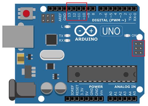
SPI Pins in Arduino
|
SPI Line |
Pin in Arduino |
|
MOSI |
11 or ICSP-4 |
|
MISO |
12 or ICSP-1 |
|
SCK |
13 or ICSP-3 |
|
SS |
10 |
Components Required
- STM32F103C8
- Arduino
- LCD 16x2 - 2
- 10k Potentiometer – 4
- Breadboard
- Connecting Wires
Circuit Diagram and Connections for STM32 SPI Tutorial


The Table Below shows the Pins Connected for STM32 SPI communication with Arduino.
|
SPI Pin |
STM32F103C8 |
Arduino |
|
MOSI |
PA7 |
11 |
|
MISO |
PA6 |
12 |
|
SCK |
PA5 |
13 |
|
SS1 |
PA4 |
10 |
The table below shows the pins connected for Two LCD (16x2) with STM32F103C8 and Arduino separately.
|
LCD pin |
STM32F103C8 |
Arduino |
|
VSS |
GND |
GND |
|
VDD |
+5V |
+5V |
|
V0 |
To Potentiometer Centre PIN for LCD contrast |
To Potentiometer Centre PIN for LCD contrast |
|
RS |
PB0 |
2 |
|
RW |
GND |
GND |
|
E |
PB1 |
3 |
|
D4 |
PB10 |
4 |
|
D5 |
PB11 |
5 |
|
D6 |
PC13 |
6 |
|
D7 |
PC14 |
7 |
|
A |
+5V |
+5V |
|
K |
GND |
GND |
Important:
- Don’t forget to connect the Arduino GND and STM32F103C8 GND together.
STM32 SPI Programming
The programming is similar to the Arduino code. The same <SPI.h> library is used in programming STM32F103C8. It can be programmed using USB port without using FTDI programmer, to learn more about programming STM32 with Arduino IDE follow the link.
In this STM32 SPI Example, we will use Arduino UNO as Slave and STM32F103C8 as Master with Two 16X2 LCD display attached to each other separately. Two Potentiometers are also connected with STM32 (PA0) and Arduino (A0) to determine the sending values (0 to 255) from master to slave and slave to master by varying the potentiometer.
Analog input is taken at STM32F10C8 pin PA0 (0 to 3.3V) by rotating the potentiometer. Then this input value is converted into Analog to Digital value (0 to 4096) and this digital value is further mapped to (0 to 255) as we can send only 8-bit (byte) data through SPI communication at once.
Similarly in Slave side we take analog input value at Arduino pin A0 from (0 to 5V) by using potentiometer. And again this input value is converted into Analog to Digital value (0 to 1023) and this digital value is further mapped to (0 to 255)
This tutorial has two programs one for master STM32 and other for slave Arduino. Complete programs for both the sides are given at the end of this project with a demonstration Video.
Master STM32 SPI Programming Explanation
1. First of all we need to include the SPI library for using SPI communication functions and LCD library for using LCD functions. Also define LCD pins for 16x2 LCD. Learn more about interfacing LCD with STM32 here.
#include<SPI.h>
#include<LiquidCrystal.h>
const int rs = PB0, en = PB1, d4 = PB10 , d5 = PB11 , d6 = PC13, d7 = PC14;
LiquidCrystal lcd(rs,en,d4,d5,d6,d7);
2. In void setup()
- Start Serial Communication at Baud Rate 9600.
Serial.begin(9600);
- Next begin the SPI communication
SPI.begin();
- Then set the Clock divider for SPI communication. I have set divider 16.
SPI.setClockDivider(SPI_CLOCK_DIV16);
- Next set the SS pin HIGH since we didn’t start any transfer to slave arduino.
digitalWrite(SS,HIGH);
3. In void loop()
- Before sending any value to slave we need to LOW the slave select value to begin transfer to slave from master.
digitalWrite(SS, LOW);
- Next read the analog value from the master STM32F10C8 POT attached to pin PA0.
int pot = analogRead(PA0);
Then convert this value in terms of one byte (0 to 255).
byte MasterSend = map(pot,0,4096,0,255);
- Here comes the important step, in the following statement we send the converted POT value stored in Mastersend variable to the slave Arduino, and also receive value from slave Arduino and stored that in mastereceive variable.
Mastereceive = SPI.transfer(Mastersend);
- Next display those received values from the slave arduino with a delay of 500 microseconds and then continuously receive and display the values.
Serial.println("Slave Arduino to Master STM32");
Serial.println(MasterReceive  lcd.setCursor(0,0);
 lcd.print("Master: STM32");
 lcd.setCursor(0,1);
 lcd.print("SalveVal:");
 lcd.print(MasterReceive  delay(500);
 digitalWrite(SS, HIGH);
Note: We use serial.println() to view the result in Serial Motor of Arduino IDE.
Slave Arduino SPI Programming Explanation
1. Same as master, first of all we need to include the SPI library for using I2C communication functions and LCD library for using LCD functions. Also define LCD pins for 16x2 LCD.
#include<SPI.h>
#include<LiquidCrystal.h>
 LiquidCrystal lcd(2, 3, 4, 5, 6, 7);    // Define LCD Module Pins (RS,EN,D4,D5,D6,D7)
2. In void setup()
- We Start Serial Communication at Baud Rate 9600.
Serial.begin(9600);
- Below statement sets MISO as OUTPUT (Have to Send data to Master IN).So data is sent via MISO of Slave Arduino.
pinMode(MISO,OUTPUT);
- Now Turn on SPI in Slave Mode by using SPI Control Register
SPCR |= _BV(SPE);
- Then turn ON interrupt for SPI communication. If a data is received from master the Interrupt Service Routine is called and the received value is taken from SPDR (SPI data Register)
SPI.attachInterrupt();
- The value from master is taken from SPDR and stored in Slavereceived variable. This takes place in following Interrupt Routine function.
ISR (SPI_STC_vect)
{
  Slavereceived = SPDR;
  received = true;
}
3. Next in void loop ()
- Read the analog value from the Slave Arduino POT attached to pin A0.
int pot = analogRead(A0);
- Convert that value in terms of one byte as 0 to 255.
Slavesend = map(pot,0,1023,0,255);
- Next important step is to send the converted value to the Master STM32F10C8, so place the value in the SPDR register. The SPDR register is used to send and receive values.
SPDR = Slavesend;
- Then display the received value (SlaveReceive) from Master STM32F103C8 on LCD with a delay of 500 microseconds and then continuously receive and display those value.
 lcd.setCursor(0,0);
 lcd.print("Slave: Arduino");
 lcd.setCursor(0,1);
 lcd.print("MasterVal:");
 Serial.println("Master STM32 to Slave Arduino");
 Serial.println(SlaveReceived);
 lcd.print(SlaveReceived);
 delay(500);
By rotating the Potentiometer at one side, you can see the varying values on LCD on another side:

So this is how SPI communication takes place in STM32. Now you can interface any SPI sensor with STM32 board.
The complete coding for Master STM32 and Slave Arduino is given below with a demonstration video
Complete Project Code
Master STM32 SPI
//SPI Master code for STM32F103C8

//SPI Communication between STM32 & Arduino

//Circuit Digest
#include<SPI.h>                                                               // Including Library for using SPI Communication
#define SS PA4
#include<LiquidCrystal.h>                                                     // Including LCD display library
const int rs = PB0, en = PB1, d4 = PB10 , d5 = PB11 , d6 = PC13, d7 = PC14;   // Declaring pin names and pin numbers of lcd
LiquidCrystal lcd(rs,en,d4,d5,d6,d7);                                         // Setting lcd and its paramaters
void setup (void)
{

  lcd.begin(16,2);                                                            // Setting lcd as 16x2 mode

  lcd.setCursor(0,0);                                                         // Setting cursor at first row and first column

  lcd.print("CIRCUIT DIGEST");                                                // Puts CIRCUIT DIGEST in LCD

  delay(3000);                                                                // Delays for 3 seconds

  lcd.clear();                                                                // Clears lcd display


  Serial.begin(9600);                                                         // Starts Serial Communication at Baud Rate 9600

  pinMode(SS,OUTPUT);                                                         // Puts SS as Output

  SPI.begin();                                                                // Begins the SPI commnuication

  SPI.setClockDivider(SPI_CLOCK_DIV16);                                       // Sets clock for SPI communication at 16 (72/16=4.5Mhz)

  digitalWrite(SS,HIGH);                                                      // Setting SlaveSelect as HIGH (So master doesnt connnect with slave)

}
void loop(void)

{


  byte MasterSend,MasterReceive;


  int pot = analogRead(PA0);                                                   // Analog read the input pot value at pin PA0


  MasterSend = map(pot,0,4096,0,255);                                          // Used to convert pot value in terms of 0 to 255 from 0 to 4096


  digitalWrite(SS, LOW);                                                       // Starts communication with Slave connected to master


  MasterReceive=SPI.transfer(MasterSend);                                      // Send the mastersend value to slave also receives value from slave

  Serial.println("Slave Arduino to Master STM32");                             // Used in Serial Monitor

  Serial.println(MasterReceive);                                               // Puts value Received im Serail Monitor

  lcd.setCursor(0,0);

  lcd.print("Master: STM32");

  lcd.setCursor(0,1);

  lcd.print("SalveVal:");

  lcd.print(MasterReceive);                                                    // Puts the received value from slave arduino

  delay(500);

  digitalWrite(SS, HIGH);                                                      // Again make SS line HIGH so that it doesnt communicate with Slave

  lcd.clear();
}

Slave Arduino SPI
//SPI Slave Code for Arduino

//SPI Communication between STM32F103C8 & Arduino

//Circuit Digest

#include<SPI.h>                           // Including Library for using SPI Communication

#include<LiquidCrystal.h>                 // Including LCD display library

LiquidCrystal lcd(2, 3, 4, 5, 6, 7);      // Define LCD Module Pins (RS,EN,D4,D5,D6,D7)

volatile boolean received;

volatile byte SlaveReceived,Slavesend;

void setup()
{

  lcd.begin(16,2);                        // Initilize LCD display

  lcd.setCursor(0,0);                     // Sets Cursor at first line of Display

  lcd.print("CIRCUIT DIGEST");            // Prints CIRCUIT DIGEST in LCD

  delay(3000);                            // Delay for 3 seconds

  lcd.clear();                            // Clears LCD display


  Serial.begin(9600);                     // Starts Serial Communication at Baud Rate 9600


  pinMode(MISO,OUTPUT);                   // Sets MISO as OUTPUT (Have to Send data to Master IN (STM32F103C8)
  SPCR |= _BV(SPE);                       // Turn on SPI in Slave Mode

  received = false;

  SPI.attachInterrupt();                  // Interuupt ON is set for SPI commnucation

}
ISR (SPI_STC_vect)                        // Inerrrput routine function

{

  SlaveReceived = SPDR;                   // Value received from master STM32F103C8 is stored in variable slavereceived

  received = true;                        // Sets received as True

}
void loop()

{

  int pot = analogRead(A0);               // Analog read the input pot value from analog pin A0

  Slavesend = map(pot,0,1023,0,255);      // Converts the value pot (0-1023) to (0-255) for sending to master stm32


  SPDR = Slavesend;                       // Sends the salvesend value to master STM32F103C8 via SPDR

  lcd.setCursor(0,0);

  lcd.print("Slave: Arduino");

  lcd.setCursor(0,1);

  lcd.print("MasterVal:");

  Serial.println("Master STM32 to Slave Arduino");

  Serial.println(SlaveReceived);                   // Puts the received value from Master STM32F103C8 at Serial Monitor

  lcd.print(SlaveReceived);                        // Puts the received value from Master STM32F103C8 at LCD display

  delay(500);

  lcd.clear();

}
