
Traditional alarm clocks have remained fundamentally unchanged for decades. The ESP32 speaking alarm clock built in this tutorial replaces the beep at a scheduled time and expects the user to interpret the reason for the beep. While functional, this approach lacks intelligence and context. Modern embedded systems enable the creation of smarter devices that communicate more effectively. This DIY Speaking Alarm Clock is developed using the XIAO ESP32-S3 microcontroller and a cloud-based Text-to-Speech (TTS) engine. Instead of producing a simple tone, the device announces the current time and reads a custom message aloud at the scheduled moment. By leveraging ESP32 Text-to-Speech capabilities using AI, the system delivers natural-sounding voice output without complex local processing. The alarm can be configured wirelessly using a web interface hosted directly on the ESP32. The project combines Wi-Fi connectivity, web server functionality, NTP time synchronisation, I2S audio output, OLED display control, and cloud TTS services into a single practical embedded application. This tutorial explains the complete design, hardware connections, firmware logic, and implementation steps required to build the system. For more innovative applications and tutorials combining microcontrollers with machine learning and voice intelligence, explore our growing library of Artificial Intelligence projects and the full collection of ESP32 projects.
What You Will Build: A Standalone ESP32 Speaking Alarm Clock
- Uses an artificial intelligence voice to tell the accurate time with a custom reminder message using a real speaker
- Syncs time automatically using Wi-Fi without having an RTC Module
- Contains an alarm management web page that can be accessed through a web browser in your local computer network
- Can support different alarms that each have their own unique spoken message
- Will have a 0.96 “ OLED” with live clock data & next alarms.
Table of Contents
Overview of the Project
The goal of this project is to design a smart alarm clock that is easy to configure and user-friendly. The device connects to a Wi-Fi network, synchronises its time with NTP servers, and hosts a web page for managing alarms. Each alarm consists of a specific time and a custom text message. When the alarm time arrives, the ESP32 sends that text to a cloud TTS engine, receives the generated audio, and plays it through a speaker. Along with voice output, a small OLED display shows the current time and the next scheduled alarm. A physical push button is also included, allowing the user to stop the alarm instantly without accessing the web interface. The entire system operates as a standalone device that only requires internet connectivity and power. It is an ideal starting point for anyone exploring ESP32 speaking clock Arduino development or ESP32 speaking clock programming for IoT reminder applications.
System Architecture of the Speaking Alarm Clock
The speaking alarm clock follows a simple and practical architecture built around the XIAO ESP32-S3 as the central controller. The ESP32 connects to the local Wi-Fi network, keeps track of time using an online time server, and runs a small web server that lets users configure alarms directly in a browser. It acts as the system's brain, managing everything from time calculations to user interactions. When an alarm is set, the ESP32 continuously compares the current time with the stored alarm times. Once a match occurs, it prepares the message, sends the text to the cloud text-to-speech service, receives the generated audio, and forwards it through the I2S interface to the MAX98357A amplifier, which drives the speaker. At the same time, the OLED display shows the current time and upcoming alarm information so that the device remains useful even without opening the web page. This approach builds upon concepts explored in our Arduino Smart Alarm Clock project, now enhanced with cloud-based voice capabilities. All parts work together in a straightforward flow, with the microcontroller handling control logic, the cloud handling voice generation, and the audio hardware handling sound output.
ESP32 Speaking Alarm Clock- System Architecture at a Glance
| Subsystem | Hardware / Service | Role |
| Microcontroller | XIAO ESP32-S3 | Central control, Wi-Fi, web server, alarm logic |
| Timekeeping | NTP (pool.ntp.org) + millis() | Accurate real-time clock without a dedicated RTC chip |
| Text-to-Speech | Wit.ai Cloud TTS API | Converts alarm message text to natural voice audio |
| Audio Output | MAX98357A I2S amplifier + speaker | Amplifies digital I2S audio to drive a 4 Ω / 8 Ω speaker |
| Display | 0.96-inch I²C OLED (SSD1306) | Shows live clock and next alarm without opening a browser |
| User Input | Tactile push button | Instantly silences the active alarm announcement |
| Configuration UI | ESP32 HTTP web server (port 80) | Browser interface for adding, editing, and deleting alarms |
Features of the ESP32 Speaking Alarm Clock
The speaking alarm clock focuses on simplicity, usability, and smart functionality rather than unnecessary complexity. It replaces the traditional buzzer with clear voice announcements and allows users to manage everything wirelessly through a browser. The device combines internet connectivity, audio playback, and a small display to create a modern and convenient alarm system that feels intuitive for everyday use.
- Announces the current time and a custom message using natural voice instead of a buzzer
- Connects to Wi-Fi for automatic time synchronisation
- Browser-based web interface for setting, editing, and deleting alarms
- Supports multiple alarms with individual messages
- An OLED display for showing the current time and the next alarm
- I2S digital audio output for clean sound
- Physical push button to instantly stop the alarm
- Compact and low-power hardware design
- Easy to modify and expand for other notification or reminder applications
Components Required for DIY Speaking Alarm Clock
The image shows the visual representation of the components used to build the Speaking Alarm Clock.
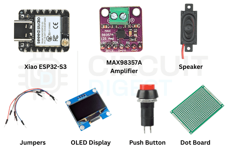
The required components are listed in the table below. All components are readily available on popular Indian electronics platforms such as Robu.in, Quartz Components and DigiKey India.
| Component | Quantity | Notes |
| XIAO ESP32 Development Board | 1 | Microcontroller with Wi-Fi support |
| MAX98357A Amplifier | 1 | 4 or 8 ohm speaker to play audio |
| Speaker | 1 | To announce the alarm |
| 0.96” OLED Display | 1 | To display the time and the next alarm |
| Push Button Switch | 1 | Alarm stop button |
| Connecting Wires | As required | Connecting Wires |
Hardware Connections and ESP32 Speaking Clock Pinout
The circuit diagram below shows the complete wiring for the ESP32 speaking clock pinout.

MAX98357A I2S Amplifier → XIAO ESP32-S3
To connect the MAX98357A amplifier, follow the circuit connections mentioned below.
| Module | Signal / Pin | Connects to ESP32-S3 Pin |
| MAX98357A Amplifier | BCLK | D8 |
| LRC | D9 | |
| DIN | D10 | |
| GND | GND | |
| Vin | 5V | |
| OLED Display | SDA | D5 |
| SCL | D4 | |
| VCC | 3.3V | |
| GND | GND | |
| Push Button | One Side | D1 |
| Other Side | GND |
*Note: The button is configured as active LOW using an internal pull-up.
How the ESP32 Speaking Alarm Clock Works
The speaking alarm clock combines Wi-Fi connectivity, real-time clock management, and cloud-based speech generation into a single, compact system. When the device powers on, the ESP32-S3 immediately connects to the configured wireless network. After establishing the connection, it retrieves the current time from an online time server to ensure accurate timekeeping. Instead of repeatedly contacting the server, the device stores this time internally and updates it using its built-in timer, allowing the clock to run continuously even if the internet becomes temporarily unavailable.
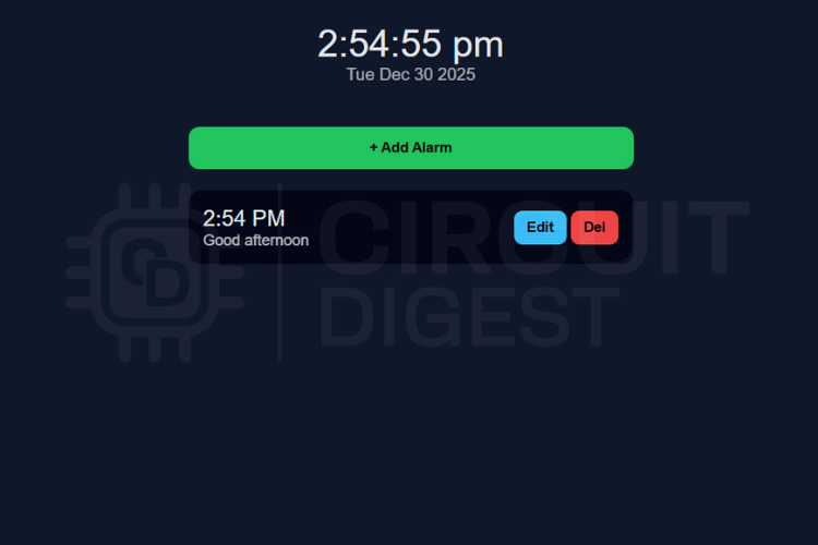
Once the time is set, the ESP32 starts an internal web server that hosts a simple control page. Users can open this page from any phone or computer connected to the same network and set alarms with custom messages. These alarms are saved in the microcontroller’s memory. The system continuously checks the current time in the background and compares it with the stored alarm times. When the time matches an alarm, the ESP32 prepares a spoken sentence that includes both the time and the user’s message. This text is sent to the cloud-based text-to-speech service, which converts it into natural voice audio. The generated audio data is then transmitted through the I2S interface to the MAX98357A amplifier, which drives the speaker and plays the announcement clearly. If you want to explore more projects built around remote monitoring and wireless control, our IoT projects collection covers a wide range of practical builds.
At the same time, the OLED display shows the current time and the next scheduled alarm so the user can quickly view the system status. If the alarm is no longer needed, pressing the push button immediately stops the voice playback. In this way, the device provides a simple, reliable flow: it connects to the internet for time and speech services and processes alarms locally. It delivers clear spoken notifications through the speaker.
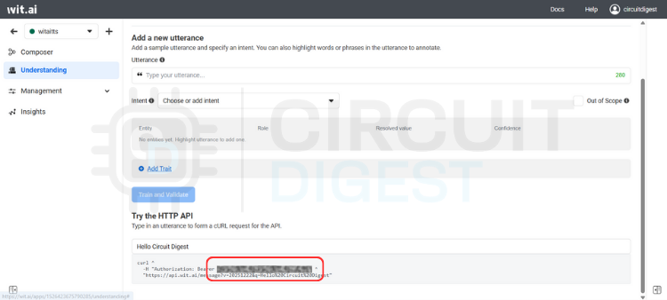
Configuring Wi-Fi and Wit.ai TTS Credentials for the ESP32 Talking Clock
Before the speaking alarm clock can function properly, the device must connect to the internet and access the cloud-based text-to-speech service. The internet connection allows the ESP32-S3 to synchronise the correct time from online servers and also communicate with the Wit.ai platform to generate natural voice announcements. Without Wi-Fi, the system may still power on and display time, but it will not be able to fetch accurate time updates or convert alarm messages into speech.
To set this up, open the firmware in the Arduino IDE and locate the section that defines the Wi-Fi network name, password, and Wit.ai access token. Replace these values with your own network credentials so the ESP32 can connect automatically after boot. Next, create a free account on Wit.ai and generate a server access token for your application. This token serves as a secure key that authorises your device to use the text-to-speech service. Once copied into the code and uploaded, the ESP32 will use this token whenever it needs to convert text into audio.
If you are new to the WitAITTS library or unsure about creating the token, you can follow this step-by-step Wit.ai setup guide for a complete walkthrough. After entering all credentials and uploading the program, open the Serial Monitor to confirm that the ESP32 connects successfully to Wi-Fi and receives an IP address. At this point, the system is fully configured and ready to synchronise time, host the web interface, and generate clear spoken alarm messages whenever required.
Alarm Scheduling Logic in the ESP32 Speaking Clock Arduino Firmware
The alarm scheduling system operates as a simple digital timetable within the ESP32, where all alarms are stored and managed locally. The firmware creates a small structure that holds the hour, minute, custom message, and a status flag for each alarm. The device supports up to ten alarms at a time, which is more than enough for daily reminders. When a user opens the web page, they can easily add a new alarm, edit the time, or delete an existing one, and the browser immediately sends those changes to the ESP32, where the data is saved in memory. This makes the process feel instant and convenient, since everything happens wirelessly without touching the hardware. The alarm scheduling mechanism is a practical example of ESP32 speaking clock programming:
During normal operation, the ESP32 constantly tracks the current time and compares it with every stored alarm in the background. When the hour and minute match an alarm entry, the system triggers it immediately. The firmware then marks the alarm as completed, so it does not repeat in the same minute. After that, it builds a spoken sentence using the current time and the user’s message and sends it to the text-to-speech engine for announcement through the speaker. This continuous checking method keeps alarms accurate and reliable while ensuring the device responds exactly at the scheduled time, without delay or complex processing.
Source Code Explanation — ESP32 Speaking Clock Programming Guide
The firmware begins by defining the network credentials and the Wit.ai access token using the lines
1. Credential Constants
const char* WIFI_SSID = "WIFI-SSID";
const char* WIFI_PASSWORD = "WIFI-PASSWORD";
const char* WIT_TOKEN = "WIT.AI-API-KEY";
These three lines store the Wi-Fi name, password, and cloud API key, allowing the ESP32 to connect to the internet and use the text-to-speech service. Without these values, the device cannot synchronise time or generate spoken messages. They serve as the system's identity and authorisation. The ESP32 reads these values during startup and automatically connects to the configured services.
2. Epoch-Based Timekeeping (No RTC Required)
The timekeeping logic is handled mainly by the line
uint32_t nowEpochUTC() { return baseEpochUTC + (millis() - baseMillis) / 1000;}This function calculates the current time by adding the elapsed seconds since boot to the base time received from the NTP server. Instead of requesting time repeatedly from the internet, the device tracks time locally using the internal millisecond counter. This reduces network usage and improves reliability. It ensures the clock keeps running even if Wi-Fi disconnects later.
3. Alarm Array Declaration
The alarm storage mechanism is defined using.
Alarm alarms[MAX_ALARMS];This line creates an array that can hold multiple alarm entries inside memory. Each entry contains hour, minute, message text, and a played flag. Using a fixed-size array keeps memory usage predictable and avoids dynamic allocation issues. It also allows the system to quickly loop through all alarms and check which one should trigger.
4. HTTP Web Server Initialisation
The web server starts listening for browser requests using
WebServer server(80);This line creates an HTTP server on port 80, allowing the ESP32 to host the alarm configuration page. When users open the device IP or alarm .local, this server handles the requests and serves the HTML interface. It also processes commands such as add, edit, and delete alarms. This is what enables wireless control from a phone or laptop.
5. Alarm Trigger Condition
The most important action happens inside the loop with
if(h24==alarms[i].hour && m==alarms[i].minute)This condition checks whether the current time matches any of the stored alarm times. The firmware compares the hour and minute continuously for every alarm in memory. When both values match, the system understands that the alarm should trigger immediately. This simple comparison ensures accurate timing without complex scheduling algorithms.
6. TTS Speech Command
Finally, the alarm announcement is produced using
tts.speak("The time is "+String(h12)+" "+String(m)+" "+ap+". "+alarms[i].message);This line sends the constructed sentence to the Wit.ai text-to-speech engine. It combines the current time and the user’s custom message into one readable phrase. The library converts this text into real voice audio and streams it to the speaker. This single command turns a basic alarm into a speaking assistant.
Testing and Demonstration of the DIY Speaking Alarm Clock
Follow this checklist to verify that every feature of the ESP32 speaking alarm clock is working correctly after the first upload.
After completing the hardware connections and uploading the firmware, the system can be tested to verify that all features work as expected. Power on the ESP32 and wait a few seconds for it to connect to the Wi-Fi network. Once connected, open a browser on your phone or computer and enter the device address or alarm.local to access the control page. The OLED display should immediately display the current time, confirming that time synchronisation is working correctly. Next, create a test alarm by setting the time a few minutes ahead and entering a simple message. Save the alarm and wait for the scheduled time. When the time matches, the speaker should clearly announce the time along with the custom message. Press the push button to ensure the alarm stops instantly, confirming that manual control works properly.
During testing, verify that alarms can be added, edited, and deleted without restarting the device. Also, check that the voice output remains clear and that the web interface updates correctly in real time. This complete demonstration ensures that Wi-Fi connectivity, timekeeping, alarm scheduling, and cloud-based speech generation work together smoothly in real-world conditions.
Applications and Limitations of the ESP32 Speaking Alarm Clock
This speaking alarm clock is designed as a practical, user-friendly smart reminder system for everyday use. Instead of relying on loud buzzers, it delivers clear voice announcements that communicate useful information. Because it connects to Wi-Fi and provides a browser-based interface, users can easily control it from any device without special software. The compact hardware and simple design also make it suitable for both personal and educational projects. However, since the system relies on internet connectivity and stores alarms only in temporary memory, there are a few operational limitations to consider in real-world use.
Practical Applications
- Smart bedside speaking alarm clock
- Medication and health reminders for elderly users
- Study and exam schedule alerts for students
- Office meeting and task notifications
- Voice-based reminder system for visually impaired users
- General IoT announcement or notification device
Current Limitations
- Requires an active internet connection for text-to-speech functionality
- Alarms are lost after a power reset or restart
- No password protection for the web interface
- Supports only a fixed number of alarms
- Works only on the configured Wi-Fi network
Possible Improvements and Future Enhancements
While the current design works reliably, several enhancements can make the system more robust and closer to production readiness. Adding local storage and offline features would improve reliability, and security improvements would make it safer for daily use. The modular firmware structure allows these upgrades without major redesign. With a few additions, the same hardware platform can support more advanced features and a better user experience. The following improvements are recommended for anyone building a production-grade or long-term deployment version of this DIY speaking alarm clock:
| Enhancement | Benefit | Implementation Hint |
| Flash-persistent alarm storage | Alarms survive reboots and power cuts | Use Preferences or SPIFFS / LittleFS to serialise the alarm array to flash on every change |
| Offline buzzer / pre-recorded audio fallback | Alarm fires even without the internet | Store short WAV files in SPIFFS and play them via I2S when the TTS request fails or times out |
| Web interface password protection | Prevents unauthorised alarm changes | Add HTTP Basic Auth or a simple PIN page before serving alarm management routes |
| Over-the-Air (OTA) firmware updates | Update firmware without USB connection | Enable ArduinoOTA library in setup(); protect with a password |
| Multi-timezone and language support | International usability | Store timezone offset in flash; pass voice parameter to Wit.ai API for non-English TTS |
| Battery backup (LiPo + TP4056) | Uninterrupted operation during power cuts | Add a TP4056 charging module and a 1 000 mAh LiPo; the XIAO ESP32-S3 supports direct battery connection |
| Volume control (hardware or software) | Adjustable announcement volume | Scale the I2S sample values in firmware, or connect a 10 kΩ potentiometer between the MAX98357A output and the speaker |
| Recurring alarm support (daily / weekday) | No need to re-add alarms every day | Add a repeat field (none/daily / Mon-Fri) to the Alarm struct and modify the played reset logic accordingly |
accordingly. ESP32ssible Improvements:
- Store alarms in flash memory so they persist after reboot
- Add an offline pre-recorded voice or buzzer fallback when the internet is unavailable
- Implement login or password protection for the web interface
- Add over-the-air firmware updates for easy maintenance
- Support multiple time zones and language options
- Include battery backup for uninterrupted operation
- Add volume control or external speaker options
- Expand the number of supported alarms
Troubleshooting the ESP32 Speaking Clock
| Problem | Possible Cause | Solution |
| Device not connecting to Wi-Fi | Incorrect SSID or password | Verify credentials in code and re-upload firmware |
| Web page not opening | Wrong IP or mDNS not detected | Check the Serial Monitor for IP and open it directly |
| No sound from the speaker | I2S wiring or amplifier issue | Recheck MAX98357A connections and power supply |
| Speech not generated | Invalid or missing Wit.ai token | Regenerate the token and update the firmware |
| OLED display blank | I2C wiring or address mismatch | Verify SDA, SCL, and display address |
| Alarm not triggering | Time not synchronised | Restart the device and confirm the internet connection |
| Alarm not stopping | Button wiring issue | Check the button connection and active LOW configuration |
Frequently Asked Questions About the ESP32 Speaking Alarm Clock
⇥ Does the alarm clock work without an internet connection?
The device can still power on and display the current time without an internet connection, but the speaking feature will not work. The system requires Wi-Fi to synchronise time accurately and to contact the cloud text-to-speech service to generate voice output. Without the internet, alarms cannot be announced through speech. In such cases, only the visual display will function.
⇥ How many alarms can be set at the same time?
The current firmware supports up to ten alarms stored in memory. This limit was chosen to keep memory usage stable and predictable on the ESP32. For most daily use cases, such as reminders, meetings, or schedules, ten alarms are more than sufficient. The limit can be increased later by modifying the code if required.
⇥ Can I change the alarm message for each reminder?
Yes, every alarm can have its own custom message. When setting an alarm through the web interface, you can enter any text, such as “Wake up,” “Attend meeting,” or “Take medicine.” When the alarm triggers, the device reads out this exact message using natural speech. This makes the system more informative than a regular buzzer alarm.
⇥ Why is the Wit.ai token required in the code?
The Wit.ai token serves as an authorisation key that enables the ESP32 to access the online text-to-speech service. It verifies that your device has permission to send text and receive audio from the cloud. Without this token, the speech feature will fail even if Wi-Fi is connected. You only need to generate it once and paste it into the firmware.
⇥ Can this project be modified for other voice notification applications?
Yes, the design is highly flexible and can be reused for many purposes beyond an alarm clock. The same setup can be adapted for reminder systems, classroom announcements, medication alerts, or smart home notifications. Since the system already supports Wi-Fi, web control, and speech output, adding new features only requires small changes in the firmware. This makes it a good foundation for many IoT-based voice projects.
GitHub Repository
The complete source code, wiring details, and project files are available in the GitHub repository for reference and reuse.


Conclusion
In this project, a simple speaking alarm clock was upgraded to a smart, interactive speaking assistant using the XIAO ESP32-S3 and a cloud-based text-to-speech service. Instead of relying on traditional buzzer sounds, the system announces the current time along with a custom message, which makes reminders more informative and user-friendly. By combining Wi-Fi connectivity, a built-in web server, an OLED display, and an I2S audio amplifier, the device offers both convenience and modern functionality while keeping the hardware minimal and affordable.
Whether you use it as a bedside alarm, a medication reminder for a family member, or as a learning platform for ESP32 speaking clock Arduino development and ESP32 speaking clock programming, the architecture is intentionally open for extension. The project also demonstrates how easily IoT features can be integrated into everyday devices. Users can configure alarms wirelessly from any browser, and the ESP32 handles scheduling, timekeeping, and voice playback automatically in the background. With small improvements, such as offline storage, stronger security, and additional customisation, this design can be extended into a fully featured smart notification system. This speaking alarm clock serves as a practical example of how embedded systems and cloud services can work together to create useful real-world applications. For more projects at the intersection of ESP32, IoT, and audio, explore our complete electronics projects library, for hardware builds across every skill level, or dive deeper into speech and AI applications in the ESP32 Text-to-Speech with Wit.ai guide.
Innovative ESP32-Based Projects
ESP32 projects that demonstrate how to build smart, connected, and interactive IoT systems using simple and practical ideas, along with real-world applications. These projects also highlight how ESP32 can be used for communication, automation, and intelligent features in embedded systems.

Build an ESP32 Text-to-Speech Offline System
An ESP32 offline text-to-speech system converts typed text into spoken words using the Talkie library and LPC audio, generating speech directly via DAC without internet, making it fast, reliable, and ideal for standalone embedded applications.

ESP32 Offline Voice Recognition Using Edge Impulse
An ESP32 offline voice recognition system uses Edge Impulse and an INMP441 microphone to capture audio, process it with on-device machine learning, and detect custom wake words and commands without internet, enabling fast, private, and real-time voice control for IoT applications.
Build a Smart ESP32 GPS Tracker with SIM800L and NEO6M Module
ESP32 GPS tracker combines a Neo-6M module for accurate location data and a SIM800L GSM module for real-time transmission over cellular networks, enabling reliable tracking without Wi-Fi and displaying data on a cloud dashboard for applications like vehicle and asset monitoring.
Complete Project Code
#include <WiFi.h>
#include <WebServer.h>
#include <time.h>
#include <WitAITTS.h>
#include <ESPmDNS.h>
// -------- OLED ADDITIONS --------
#include <Wire.h>
#include <Adafruit_GFX.h>
#include <Adafruit_SSD1306.h>
// ================= CREDENTIALS =================
const char* WIFI_SSID = "YOUR_WIFI_SSID";
const char* WIFI_PASSWORD = "YOUR_WIFI_PASSWORD";
const char* WIT_TOKEN = "YOUR_API_KEY";
// ================= I2S (XIAO ESP32-S3) =================
#define I2S_BCLK 7
#define I2S_LRC  8
#define I2S_DIN  9
#define BTN_STOP 2  // Active LOW
WitAITTS tts(I2S_BCLK, I2S_LRC, I2S_DIN);
WebServer server(80);
// ================= TIME =================
uint32_t baseEpochUTC = 0;
uint32_t baseMillis = 0;
const uint32_t IST_OFFSET = 19800;
uint32_t nowEpochUTC() {
return baseEpochUTC + (millis() - baseMillis) / 1000;
}
// ================= ALARMS =================
#define MAX_ALARMS 10
struct Alarm {
uint8_t hour;
uint8_t minute;
String message;
bool played;
};
Alarm alarms[MAX_ALARMS];
uint8_t alarmCount = 0;
bool alarmKilled = false;
// ================= OLED DEFINITIONS (ADD ONLY) =================
#define SCREEN_WIDTH 128
#define SCREEN_HEIGHT 64
#define OLED_RESET   -1
Adafruit_SSD1306 display(SCREEN_WIDTH, SCREEN_HEIGHT, &Wire, OLED_RESET);
// ================= WEB PAGE =================
const char PAGE[] PROGMEM = R"rawliteral(
<!DOCTYPE html>
<html>
<head>
<meta name="viewport" content="width=device-width, initial-scale=1">
<title>Speaking Alarm Clock</title>
<style>
body{
font-family:Arial;
background:#0f172a;
color:#e5e7eb;
padding:20px;
display:flex;
justify-content:center;
}
.app{width:100%;max-width:420px}
.header{text-align:center;margin-bottom:20px}
#clock{font-size:2.2em}
#date{opacity:0.7}
.add-btn{
width:100%;
background:#22c55e;
padding:12px;
border:none;
border-radius:10px;
font-weight:bold;
margin:20px 0;
}
.alarm-card{
background:#020617;
padding:14px;
border-radius:12px;
margin-bottom:12px;
display:flex;
justify-content:space-between;
align-items:center;
}
.alarm-time{font-size:1.3em}
.alarm-msg{font-size:0.9em;opacity:0.8}
button{padding:8px 12px;border:none;border-radius:8px;font-weight:bold}
.edit-btn{background:#38bdf8}
.del-btn{background:#ef4444}
.played{opacity:0.5}
.modal{
display:none;
position:fixed;
top:0;left:0;
width:100%;height:100%;
background:rgba(0,0,0,0.6);
}
.modal-content{
background:#020617;
padding:20px;
border-radius:14px;
width:90%;
max-width:360px;
margin:100px auto;
text-align:center;
}
select,input{
width:100%;
padding:10px;
margin-top:8px;
border-radius:8px;
border:none;
}
</style>
</head>
<body>
<div class="app">
<h2 style="text-align:center">Speaking Alarm Clock</h2>
<div class="header">
<div id="clock">--:--</div>
<div id="date">--</div>
</div>
<button class="add-btn" onclick="openModal()">+ Add Alarm</button>
<div id="alarms"></div>
</div>
<div class="modal" id="modal">
<div class="modal-content">
  <h3 id="modalTitle">Set Alarm</h3>
  <select id="hour"></select>
  <select id="minute"></select>
  <select id="ampm"><option>AM</option><option>PM</option></select>
  <input id="msg" placeholder="Alarm message">
  <button class="add-btn" onclick="saveAlarm()">Save</button>
</div>
</div>
<script>
var epochUTC=0;
var alarmList=[];
var editIndex=null;
function tick(){
epochUTC++;
var d=new Date(epochUTC*1000);
clock.innerText=d.toLocaleTimeString("en-IN",{timeZone:"Asia/Kolkata",hour12:true});
date.innerText=d.toDateString();
}
function loadAlarms(){
fetch("/alarms").then(r=>r.json()).then(data=>{
  alarmList=data;
  render();
});
}
fetch("/epoch").then(r=>r.text()).then(t=>{
epochUTC=parseInt(t);
tick();
setInterval(tick,1000);
loadAlarms();
});
for(var i=1;i<=12;i++) hour.innerHTML+="<option>"+i+"</option>";
for(var i=0;i<60;i++) minute.innerHTML+="<option>"+(i<10?"0":"")+i+"</option>";
function openModal(){
editIndex=null;
msg.value="";
modal.style.display="block";
}
function saveAlarm(){
var h=parseInt(hour.value);
var m=parseInt(minute.value);
var ap=ampm.value;
if(ap==="PM" && h!==12) h+=12;
if(ap==="AM" && h===12) h=0;
if(editIndex===null){
  fetch("/set?h="+h+"&m="+m+"&msg="+encodeURIComponent(msg.value))
    .then(()=>loadAlarms());
}else{
  fetch("/edit?id="+editIndex+"&h="+h+"&m="+m+"&msg="+encodeURIComponent(msg.value))
    .then(()=>{editIndex=null;loadAlarms();});
}
modal.style.display="none";
}
function deleteAlarm(i){
fetch("/delete?id="+i).then(()=>loadAlarms());
}
function editAlarm(i){
var a=alarmList[i];
editIndex=i;
hour.value=(a.h%12)||12;
minute.value=(a.m<10?"0":"")+a.m;
ampm.value=(a.h>=12?"PM":"AM");
msg.value=a.msg;
modal.style.display="block";
}
function render(){
var html="";
alarmList.forEach((a,i)=>{
  var h12=(a.h%12)||12;
  var ap=(a.h>=12?"PM":"AM");
  var cls=a.played?"played":"";
  html+=
  "<div class='alarm-card "+cls+"'>"+
    "<div>"+
      "<div class='alarm-time'>"+h12+":"+ (a.m<10?"0":"")+a.m +" "+ap+"</div>"+
      "<div class='alarm-msg'>"+a.msg+"</div>"+
    "</div>"+
    "<div>"+
      "<button class='edit-btn' onclick='editAlarm("+i+")'>Edit</button> "+
      "<button class='del-btn' onclick='deleteAlarm("+i+")'>Del</button>"+
    "</div>"+
  "</div>";
});
alarms.innerHTML=html;
}
</script>
</body>
</html>
)rawliteral";
// ================= HANDLERS =================
void handleRoot(){ server.send_P(200,"text/html",PAGE); }
void handleEpoch(){ server.send(200,"text/plain",String(nowEpochUTC())); }
void handleSet(){
if(alarmCount>=MAX_ALARMS){ server.send(400,"text/plain","Limit"); return; }
alarms[alarmCount++] = {
  (uint8_t)server.arg("h").toInt(),
  (uint8_t)server.arg("m").toInt(),
  server.arg("msg"),
  false
};
server.send(200,"text/plain","OK");
}
void handleEdit(){
int id=server.arg("id").toInt();
if(id<0||id>=alarmCount){ server.send(400,"text/plain","Invalid"); return; }
alarms[id].hour=server.arg("h").toInt();
alarms[id].minute=server.arg("m").toInt();
alarms[id].message=server.arg("msg");
alarms[id].played=false;
server.send(200,"text/plain","Updated");
}
void handleDelete(){
int id=server.arg("id").toInt();
if(id<0||id>=alarmCount){ server.send(400,"text/plain","Invalid"); return; }
for(int i=id;i<alarmCount-1;i++) alarms[i]=alarms[i+1];
alarmCount--;
server.send(200,"text/plain","Deleted");
}
void handleGetAlarms(){
String json="[";
for(int i=0;i<alarmCount;i++){
  json += "{\"h\":"+String(alarms[i].hour)+
          ",\"m\":"+String(alarms[i].minute)+
          ",\"msg\":\""+alarms[i].message+
          "\",\"played\":"+String(alarms[i].played?"true":"false")+"}";
  if(i<alarmCount-1) json+=",";
}
json+="]";
server.send(200,"application/json",json);
}
// ================= OLED UPDATE (ADD ONLY) =================
void updateOLED(){
display.clearDisplay();
uint32_t tIST = nowEpochUTC() + IST_OFFSET;
uint8_t h24 = (tIST / 3600) % 24;
uint8_t m = (tIST / 60) % 60;
uint8_t h12 = h24 % 12;
if(h12 == 0) h12 = 12;
String ap = (h24 >= 12) ? "PM" : "AM";
// ---------- TIME (CENTERED & BOLD) ----------
display.setTextSize(2);
// Calculate center position for HH:MM (5 chars wide * ~12px = ~60px)
int timeX = (SCREEN_WIDTH - 60) / 2;
display.setCursor(timeX, 0);
display.printf("%02d:%02d", h12, m);
// AM / PM badge
display.setTextSize(1);
display.setCursor(timeX + 64, 6);
display.print(ap);
// ---------- DIVIDER ----------
display.drawLine(0, 26, SCREEN_WIDTH, 26, SSD1306_WHITE);
// ---------- NEXT ALARM LABEL ----------
display.setTextSize(1);
display.setCursor(0, 30);
display.print("NEXT ALARM");
// Small underline for label
display.drawLine(0, 40, 60, 40, SSD1306_WHITE);
bool found=false;
for(int i=0;i<alarmCount;i++){
  if(!alarms[i].played){
    uint8_t ah12 = alarms[i].hour % 12;
    if(ah12==0) ah12=12;
    String aap = (alarms[i].hour>=12)?"PM":"AM";
    display.setCursor(0,44);
    display.printf("%02d:%02d %s", ah12, alarms[i].minute, aap.c_str());
    found=true;
    break;
  }
}
if(!found){
  display.setCursor(0,44);
  display.print("None");
}
display.display();
}
// ================= SETUP =================
void setup(){
Serial.begin(115200);
pinMode(BTN_STOP, INPUT_PULLUP);
WiFi.begin(WIFI_SSID, WIFI_PASSWORD);
while (WiFi.status() != WL_CONNECTED) delay(300);
if (!MDNS.begin("alarm")) {
  Serial.println("mDNS failed");
} else {
  Serial.println("mDNS started: http://alarm.local");
}
configTime(0, 0, "pool.ntp.org");
struct tm ti;
while (!getLocalTime(&ti) || ti.tm_year < 123) delay(500);
baseEpochUTC = mktime(&ti);
baseMillis = millis();
tts.begin(WIFI_SSID, WIFI_PASSWORD, WIT_TOKEN);
server.on("/", handleRoot);
server.on("/epoch", handleEpoch);
server.on("/set", handleSet);
server.on("/edit", handleEdit);
server.on("/delete", handleDelete);
server.on("/alarms", handleGetAlarms);
server.begin();
// -------- OLED INIT (ADD ONLY) --------
if (!display.begin(SSD1306_SWITCHCAPVCC, 0x3C)) {
  Serial.println("OLED init failed");
} else {
  display.clearDisplay();
  display.setTextColor(SSD1306_WHITE);
  display.setTextSize(1);
  display.setCursor(0,0);
  display.println("Speaking Alarm");
  display.println("Clock Ready");
  display.display();
}
}
// ================= LOOP =================
void loop(){
if(!alarmKilled) tts.loop();
server.handleClient();
uint32_t tIST = nowEpochUTC() + IST_OFFSET;
uint8_t h24 = (tIST / 3600) % 24;
uint8_t m = (tIST / 60) % 60;
for(int i=0;i<alarmCount;i++){
  if(alarms[i].played) continue;
  if(h24==alarms[i].hour && m==alarms[i].minute){
    alarms[i].played=true;
    alarmKilled=false;
    uint8_t h12=h24%12; if(h12==0) h12=12;
    String ap=(h24>=12)?"PM":"AM";
    tts.speak("The time is "+String(h12)+" "+String(m)+" "+ap+". "+alarms[i].message);
  }
}
if(digitalRead(BTN_STOP)==LOW && !alarmKilled){
  alarmKilled=true;
  tts.stop();
}
// -------- OLED UPDATE (ADD ONLY) --------
updateOLED();
delay(10);
}
