The Internet of Things (IoT) allows objects to be identified and controlled from a distance using existing network infrastructure, opening up new possibilities. greater efficiency, accuracy, and financial benefit through more direct contact between the actual and virtual worlds and computer-based systems. In order to maximize water consumption and maintain a green environment, it is important to irrigate more effectively as water supplies become increasingly scarce and polluted. The goal of this project is to create a smart houseplant watering and monitoring system that analyses and records environmental factors to help plants thrive. The sensors collect and evaluate data regarding changing weather and soil moisture levels before sending timely warnings to the user’s Android phone.
The idea of building this project came to mind when I went to my village home where I saw many people cultivating their lands. But certain instant rainfall or storms destroy their crops. But they could not know anything if they are not present during the time of rain or storm. This resulted in a huge loss by the poor farmers.
Before this, we have built many smart irrigation projects, you can check them out
- Automatic Irrigation System using an Arduino Uno
- Smart Irrigation System using Arduino and Soil Moisture Sensor
- IoT based Smart Irrigation System using Soil Moisture Sensor and ESP8266 NodeMCU
- How Does a Soil Moisture Sensor Work and how to use it with Arduino?

In the future, I am going to modify this project by adding more smart features like Rain water harvesting, tank irrigation method implementation using water collected during rainfall, Water overflow control, automatic watering to each plant from time to time, and greenhouse(with temperature and atmospheric humidity control).
Component Required for Smart Plant Monitoring
Project Hardware Used
- NodeMCU ESP8266,
- Soil Moisture Sensor,
- Temperature and Humidity sensor,
- Relay Module,
- Water Pump,
- LED Light.
Project Software Used
- Arduino IDE(for programming the ESP8266 board)
- Blynk App(for IoT control and wireless monitoring).
Project Hardware and Software Selection
I chose the NodeMCU ESP8266 board because it is a microcontroller board with an inbuilt Wi-Fi module for wireless control. I have also used a soil moisture sensor for soil moisture control and monitor and a temperature and humidity sensor for the temperature and humidity. These are all cheap and fit or a live demonstration project. I have also used a relay module for controlling the water pump for irrigation. This can be controlled accordingly.
I have used the Arduino IDE for programming the NodeMCU board. The Arduino platform is a very user friendly and easy to use application for programming and it is very much used by both students and professionals. I have also taken help from the Blynk app for wireless monitoring and controlling the full setup. We can also use the new Blynk 2.0 for better performance.
The hardware used is very simple and cost efficient. The NodeMCU is quite small and handy and also it can be available at a very cheap rate. The sensors are also very cheap. While I was making this project, I observed some problems that this project can not handle the very worst conditions of the environment. This can be made for handling worse conditions.
Smart Plant Monitoring Circuit Diagram
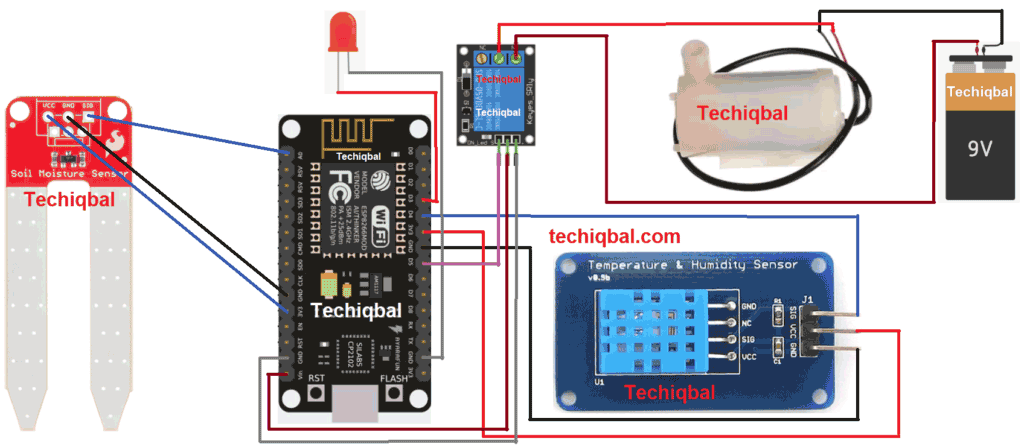
Here the soil moisture sensor is connected to the A0 pin(analog pin) of the NodeMCU. The signal pin of the DHT Temperature and Humidity sensor is connected to the D4 pin(Digital pin) of the NodeMCU. The relay module is connected to the D5 pin of the NodeMCU. Further, the motor is connected to the water pump. Also the LED is connected to the D3 pin of the NodeMCU. This is used as a light source at night for working at night and controlling via IoT.
The moisture sensor and the DHT sensor always provide an analog signal to the NodeMCU which is further preceded by the NodeMCU to check the moisture, humidity and temperature.
Complete Project Code
#define BLYNK_PRINT Serial
#include <OneWire.h>
#include <SPI.h>
#include <BlynkSimpleEsp8266.h>
#include <DHT.h>
#include <DallasTemperature.h>
#define ONE_WIRE_BUS D2
OneWire oneWire(ONE_WIRE_BUS);
DallasTemperature sensors(&oneWire);
char auth[] =”BOsoqmyvsdJSenk51n6EplHN0jqela_aajwi”;
char ssid[] = “Iqbal”;
char pass[] = “Password”;
//code written by Md iqbal
//website:-techiqbal.com
//Youtube:-Techiqbal
#define DHTPIN 2
#define DHTTYPE DHT11
DHT dht(DHTPIN, DHTTYPE);
SimpleTimer timer;
void sendSensor()
{
float h = dht.readHumidity();
float t = dht.readTemperature();

if (isnan(h) || isnan(t)) {
Serial.println(“Failed to read from DHT sensor!”);
return;
}

Blynk.virtualWrite(V5, h); //V5 is for Humidity
Blynk.virtualWrite(V6, t); //V6 is for Temperature
}
void setup()
{
Serial.begin(9600);
dht.begin();

timer.setInterval(1000L, sendSensor);
Blynk.begin(auth, ssid, pass);
sensors.begin();
}
int sensor=0;
int output=0;
void sendTemps()
{
sensor=analogRead(A0);
output=(145-map(sensor,0,1023,0,100)); //in place 145 there is 100(it change with the change in sensor)
delay(1000);
sensors.requestTemperatures();
float temp = sensors.getTempCByIndex(0);
Serial.println(temp);
Serial.print(“moisture = “);
Serial.print(output);
Serial.println(“%”);
Blynk.virtualWrite(V1, temp);
Blynk.virtualWrite(V2,output);
delay(1000);
}
void loop()
{
Blynk.run();
timer.run();
sendTemps();
}


