
The communication protocols are the integral part of a digital electronics and embedded system. Wherever there is interfacing of multiple microcontroller and peripherals, the communication protocol has to be used in order to exchange bunch of data. There are many types of serial communication protocol available. The RS485 is one of the serial communication protocol and is used in industrial projects and heavy machineries.
We learned about RS485 Serial Communication between Arduino Uno and Arduino Nano in the previous tutorial. This tutorial is about using a RS-485 Serial communication in STM32F103C8 Microcontroller. If you are new to STM32 Microcontroller then start with Getting Started with STM32 using Arduino IDE: Blinking LED and check all the STM32 projects here.
In this tutorial Master STM32F103C8 has three push buttons that are used to control the status of three LEDs present at the Slave Arduino Uno by using RS-485 Serial communication.
Let’s begin by understanding the working of RS-485 Serial communication.
RS-485 Serial Communication
RS-485 is an asynchronous serial communication protocol which doesn’t require clock. It uses a technique called differential signal to transfer binary data from one device to another.
So what is this Differential Signal Transfer Method??
Differential signal method works by creating a differential voltage by using a positive and negative 5V. It provides a Half-Duplex communication when using two wires and Full-Duplex communication when using four wires.
By using this method:
- RS-485 supports higher data transfer rate of 30Mbps maximum.
- It also provides maximum data transfer distance compared to RS-232 protocol. It transfers data up to 1200-meter maximum.
- The main advantage of RS-485 over RS-232 is the multiple slave with single Master while RS-232 supports only single slave.
- Can have a maximum of 32 devices connected to RS-485 protocol.
- Another advantage of the RS-485 is immune to the noise as they use differential signal method to transfer.
- RS-485 is faster compared to I2C protocol.
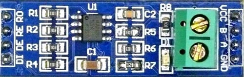
RS-485 Module can be connected to any microcontroller having serial port. For using RS-485 module with microcontrollers a module called 5V MAX485 TTL to RS485 which is based on Maxim MAX485 IC is needed as it allows serial communication over long distance of 1200 meters and it is bidirectional and half duplex has a data transfer rate of 2.5 Mbps. This module requires a voltage of 5V.
RS-485 Pin Description:
|
Pin Name |
Description |
|
VCC |
5V |
|
A |
Non-inverting Receiver Input Non-Inverting Driver Output |
|
B |
Inverting Receiver Input Inverting Driver Output |
|
GND |
GND (0V) |
|
R0 |
Receiver Out (RX pin) |
|
RE |
Receiver Output (LOW-Enable) |
|
DE |
Driver Output (HIGH-Enable) |
|
DI |
Driver Input (TX pin) |
RS485 module has following features:
- Operating voltage: 5V
- On-board MAX485 chip
- A low power consumption for the RS485 communication
- Slew-rate limited transceiver
- 5.08mm pitch 2P terminal
- Convenient RS-485 communication wiring
- All pins of chip have been lead to can be controlled through the microcontroller
- Board size: 44 x 14mm
Using this module with STM32F103C8 and Arduino UNO is very easy. The hardware serial ports of microcontrollers are used. The hardware serial pins in STM32 and arduino UNO is given below.
- In STM32F103C8: Pins PA9 (TX) & PA10 (RX)
- In Arduino Uno: Pin 0 (RX) & 1 (TX)
Programming is also simple just use the Serial.print() to write to RS-485 and Serial.Read() to read from RS-485 and the pins DE & RE of RS-485 is made LOW to receive data and made HIGH to write data to RS-485 bus.
Components Required
- STM32F103C8
- Arduino UNO
- MAX485 TTL to RS485 Converter Module - (2)
- 10K Potentiometer
- Push Button - 3
- LED - 3
- Resistors
- Breadboard
- Connecting Wires
Circuit Diagram

In this tutorial STM32F103C8 is used as Master with one RS-485 module and Arduino UNO is used as Slave with another RS-485 module.
Circuit Connection between the RS-485 and STM32F103C8 (Master):
|
RS-485 |
STM32F103C8 |
|
DI |
PA9 (TX1) |
|
DE RE |
PA3 |
|
R0 |
PA10 (RX1) |
|
VCC |
5V |
|
GND |
GND |
|
A |
To A of Slave RS-485 |
|
B |
To B of Slave RS-485 |
STM32F103C8 with Three Push button:
Three Push buttons with three Pull Down Resistor of 10k are connected to the pins PA0, PA1, PA2 of STM32F103C8.
Circuit Connection between the RS-485 and Arduino UNO (Slave):
|
RS-485 |
Arduino UNO |
|
DI |
1 (TX) |
|
DE RE |
2 |
|
R0 |
0 (RX) |
|
VCC |
5V |
|
GND |
GND |
|
A |
To A of Master RS-485 |
|
B |
To B of Master RS-485 |
Three LEDs are used where Anodes of LEDs with resistor of 330 ohms are connected to pins 4, 7, 8 of Arduino UNO and Cathode of the LEDs are connected to GND.
Programming STM32F103C8 & Arduino UNO for RS485 Serial Communication
Arduino IDE is used for development and programming of both boards i.e. STM32 and Arduino UNO. But make sure you have selected the corresponding PORT from Tools->Port and Board from Tools->Board. If you find any difficulties or doubt then just refer Programming your STM32 in ARDUINO IDE. The programming for this tutorial consists of Two section one for STM32F103C8 (Master) and other for Arduino UNO (Slave). Both the codes will be explained one by one below.
In Master side, the status of the Push Button is read and then serially written those values to the RS-485 bus through the Hardware Serial Ports 1 (PA9, PA10) of STM32F103C8. Also there is no external library needed as of now. The Arduino has all the necessary library for serial communication.
Begin Serial Communication using Hardware Serial Pins (PA9, PA10) at buadrate of 9600.
Serial1.begin(9600);
Read the status of the push button at the pins PA0, PA1, PA2 of STM32F103C8 and store them in a variable button1val, button2val, button3val. The value is HIGH if button is pressed and LOW when not pressed.
int button1val = digitalRead(button1);
int button2val = digitalRead(button2);
int button3val = digitalRead(button3);
Before sending the button values to the serial port, the pins DE & RE of RS-485 should be HIGH that is connected to the pin PA3 of STM32F103C8 (To Make pin PA3 HIGH):
digitalWrite(enablePin, HIGH);
Next to put those values in the Serial Port and send values depending upon which push button is pressed use if else statement and send the corresponding value when button is pressed.
If the first button is pressed then the condition matches and the value ‘1’ is sent to the serial port where Arduino UNO is connected.
if (button1val == HIGH)
    {
      int num1 = 1;
      Serial1.println(num1);
    }
Similarly, when button 2 is pressed the value 2 is sent over serial port and when button 3 is pressed the value 3 is sent over the serial port.
else if (button2val == HIGH)
    {
      int num2 =2;
      Serial1.println(num2);
    }
                else if (button3val == HIGH)
    {
      int num3 =3;
      Serial1.println(num3);
    }
And when no button is pressed the value 0 is sent to Arduino Uno.
   else
   {
     int num = 0;
     Serial1.println(num);
     }
This finishes programming to configure STM32 as Master.
In the Slave side the Arduino UNO receives an integer value that is sent from the Master STM32F103C8 which is available at the Hardware Serial port of the Arduino UNO (P0, 1) where the RS-485 module is connected.
Simply read value and store in a variable. Depending upon the value received the corresponding LED is turned ON or OFF connected to Arduino GPIO.
To receive the values from the Master just make the pins DE & RE of RS-485 module LOW. So the pin-2 (enablePin) of Arduino UNO is made LOW.
digitalWrite(enablePin, LOW);
Now just read the integer data available at Serial Port and store them in a variable.
int receive = Serial.parseInt();
Depending upon the value i.e. (0, 1, 2, 3) received, the correspondingly one of the three LED is turned ON.
if (receive == 1)                //Depending Upon Recieved value the corresponding LED is turned ON or OFF
        {
          digitalWrite(ledpin1,HIGH);
        }
        else if (receive == 2)
        {
          digitalWrite(ledpin2,HIGH);
        }
        else if (receive == 3)
        {
          digitalWrite(ledpin3,HIGH);
        }
        else
        {
         digitalWrite(ledpin1,LOW);
         digitalWrite(ledpin2,LOW);
         digitalWrite(ledpin3,LOW);
        }
This finishes programming and configuring Arduino UNO as Slave. Also this finishes the complete configurations for Arduino UNO and STM32. The working video and all codes are attached at the end of this tutorial.
Testing the RS485 communication between STM32F103C8 and Arduino UNO:
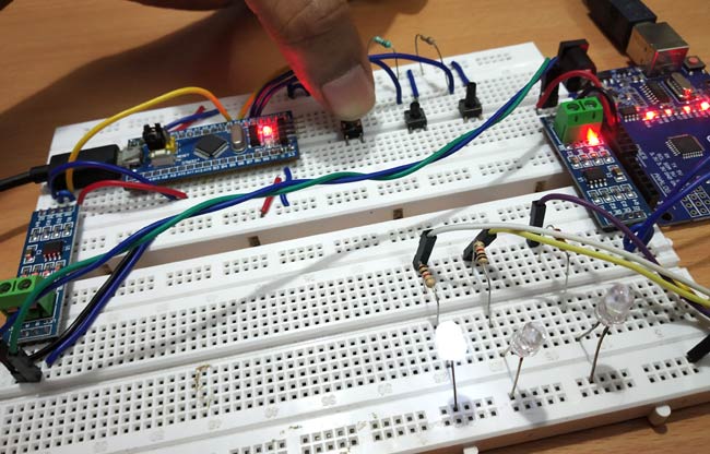
1. When Push button-1, which is connected to the Master STM32, is pressed the LED 1 Turns ON connected to the Slave Arduino.
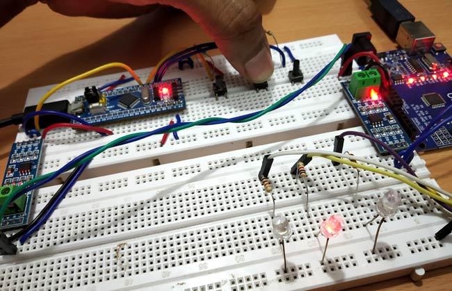
2. When Push button-2, which connected to the Master STM32, is pressed the LED 2 Turns ON connected to the Slave Arduino.
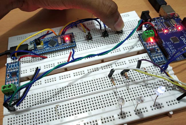
3. Similarly when Push button-3 is pressed the LED 3 Turns ON connected to the Slave Arduino.
This finishes the RS485 serial communication between STM32F103C8 and Arduino UNO. The Arduino UNO and STM32 boards are widely used boards for rapid prototyping and we have done many useful projects on these boards. If you find any doubts or have any suggestion for us then write and comment below.
Complete Project Code
Master Code:STM32F103C8
//RS-485 Serial Communication Between STM32F103C8 & Arduino Uno
#define button1 PA0

#define button2 PA1

#define button3 PA2

#define enablePin PA3


void setup()
{

  Serial1.begin(9600);            // Begins Serial communication at serial1 Port PA9,PA10 at baudrate 9600

  pinMode(enablePin, OUTPUT);
  pinMode(button1,INPUT);

  pinMode(button2,INPUT);

  pinMode(button3,INPUT);


  delay(10);

  digitalWrite(enablePin, HIGH);  //  (always high as Master Writes data to Slave)

}
void loop()

{

  int button1val = digitalRead(button1);         //Reads the status of the Push Button

  int button2val = digitalRead(button2);

  int button3val = digitalRead(button3);


    if (button1val == HIGH)

    {

      int num1 = 1;

      Serial1.println(num1);                //Sends Push button value 1 if HIGH (Pressed)

    }

    else if (button2val == HIGH)

    {

      int num2 =2;

      Serial1.println(num2);                //Sends Push button value 2 if HIGH (Pressed)

    }

    else if (button3val == HIGH)

    {

      int num3 =3;

      Serial1.println(num3);                //Sends Push button value 3 if HIGH (Pressed)

    }

   else

   {

     int num = 0;

     Serial1.println(num);                  //Sends 0 if any of push button is not pressed

   }

   delay(50);

}

Slave Code: Arduino UNO:

//RS-485 Serial Communication Between STM32F103C8 & Arduino Uno
#define enablePin 2

#define ledpin1 4

#define ledpin2 7

#define ledpin3 8
 void setup()

{

  Serial.begin(9600);                   // Begins Serial Communication with baud rate 9600

  pinMode(ledpin1,OUTPUT);

  pinMode(ledpin2,OUTPUT);

  pinMode(ledpin3,OUTPUT);

  pinMode(enablePin, OUTPUT);

  delay(10);

  digitalWrite(enablePin, LOW);        //  (Pin 8 always LOW to receive value from Master)

}
void loop()
{

  while (Serial.available())            //While having data at Serial port this loop executes

     {

        int receive = Serial.parseInt();  // Reads the integer value sent from STM32


        if (receive == 1)                //Depending Upon Recieved value the corresponding LED is turned ON or OFF

        {

          digitalWrite(ledpin1,HIGH);

        }

        else if (receive == 2)

        {

          digitalWrite(ledpin2,HIGH);

        }

        else if (receive == 3)

        {

          digitalWrite(ledpin3,HIGH);

        }

        else

        {

         digitalWrite(ledpin1,LOW);

         digitalWrite(ledpin2,LOW);

         digitalWrite(ledpin3,LOW);

        }

     }

}

Very simple project and well demonstrated Pramoth. The part where you removed the RS485 communication leads and showed no signals getting trasmitted, and reconnected to re-establish the same was nicely done.
Would be good to see if you can alter data transmission speeds to test the (practical) upper limit.