
Modbus is a Serial Communication protocol which was discovered by Modicon in 1979 and it is used for transmitting data over serial lines between the industrial electronic devices. RS-485 Modbus uses RS-485 for transmission lines. It should be noted that Modbus is a software protocol and not a hardware protocol. It is divided into two parts such as Modbus Master and Modbus Slave. In RS-485 Modbus network there is one Master and 127 Slaves each with unique address from 1 to 127. In this MAX485 Arduino project, we will use Arduino Uno as Slave for serial communication.
Modbus are mostly used in PLCs (Programmable Logic Controllers). And apart from this, the Modbus is also used in Healthcare, Transportation, Home Automation etc. Modbus has 255 function codes and there are mainly three popular versions of Modbus:
- MODBUS RTU
- MODBUS ASCII
- MODBUS/TCP
What is the difference between Modbus ASCII and Modbus RTU?
Modbus RTU and Modbus ASCII talks the same protocol. The only difference is that the bytes being transmitted over the wire are presented as binary with RTU and as readable ASCII with Modbus RTU. Modbus RTU will be used in this tutorial.
This tutorial is about using RS-485 Modbus communication with Arduino UNO as Slave. Here we install Simply Modbus Master Software in PC and control two LEDs and Servo Motor by using RS-485 as transmission line. These LEDs and servo motor are connected with Slave Arduino and controlled by sending values using Master Modbus Software. Since this tutorial uses RS-485, it is recommended to first go through RS485 Serial Communication between Arduino Uno and Arduino Nano. RS485 can also be used with other controllers for serial communication:
- RS-485 Serial Communication between Raspberry Pi & Arduino UNO
- Serial Communication Between STM32F103C8 and Arduino UNO using RS-485
Let’s begin by exploring some background about the RS-485 and Modbus. Also learn more about various Serial Communication protocols here.
RS-485 Serial Communication
RS-485 is an asynchronous serial communication protocol which doesn’t not require clock. It uses a technique called differential signal to transfer binary data from one device to another.
So what is this differential signal transfer method??
Differential signal method works by creating a differential voltage by using a positive and negative 5V. It provides a Half-Duplex communication when using two wires and Full-Duplex requires 4 fours wires.
By using this method:
- RS-485 supports higher data transfer rate of 30Mbps maximum.
- It also provides maximum data transfer distance compared to RS-232 protocol. It transfers data up to 1200-meter maximum.
- The main advantage of RS-485 over RS-232 is the multiple slave with single Master while RS-232 supports only single slave.
- Can have a maximum of 32 devices connected to RS-485 protocol.
- Another advantage of the RS-485 is immune to the noise as they use differential signal method to transfer.
- RS-485 is faster compared to I2C protocol.
Connecting RS-485 with Arduino
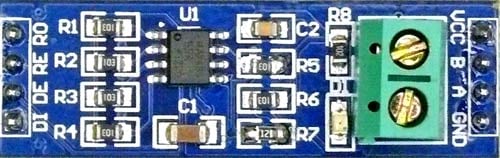
RS-485 Module can be connected to any microcontroller having serial port. For using RS-485 module with microcontrollers, a module called 5V MAX485 TTL to RS485 which is based on Maxim MAX485 IC is needed as it allows serial communication over long distance of 1200 meters. It is bidirectional and half duplex and has data transfer rate of 2.5 Mbps. This module requires a voltage of 5V.
Pin-Out of RS-485:
|
Pin Name |
Pin Description |
|
VCC |
5V |
|
A |
Non-inverting Receiver Input Non-Inverting Driver Output |
|
B |
Inverting Receiver Input Inverting Driver Output |
|
GND |
GND (0V) |
|
R0 |
Receiver Out (RX pin) |
|
RE |
Receiver Output (LOW-Enable) |
|
DE |
Driver Output (HIGH-Enable) |
|
DI |
Driver Input (TX pin) |
USB to RS-485 Converter Module
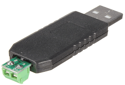
This is an USB to RS485 Converter Adapter module which supports WIN7, XP, Vista, Linux, Mac OS and provides an easy to use RS485 interface by means of using COM port in the computer. This module is plug-and-play device. There are no command structures, whatever is sent to the Virtual COM Port is automatically converted to RS485 and vice versa. The module is completely self-powered from the USB bus. So, no need of external power supply for operation.
It shows up as a Serial/COM port and is accessible from applications or hyper-terminal. This converter provides half-duplex RS-485 communication. The Baud rate range is 75 bps to 115200 bps, maximum up to 6 Mbps.
To use this device there are various Modbus Software available in the internet. In this tutorial a software called Simply Modbus Software is used.
Simply Modbus Master Software
Modbus Master Software application is needed to send data to slave Modbus RS-485 Arduino device via COM.
Simply Modbus Master is a data communication test software. You can download the Simply Modbus Master from the given link and learn more about it by referring Software Manual.
Before using the software, it is important to get familiar with the following terminologies.
Slave ID:
Each slave in a network is assigned a unique unit address from 1 to 127. When the master requests data, the first byte it sends is the Slave address. This way each slave knows after the first byte whether or not to ignore the message.
Function code:
The second byte sent by the Master is the Function code. This number tells the slave which table to access and whether to read from or write to the table.
Supported Register Function codes:
|
Function Code |
Action |
Table Name |
|
04 (04 hex) |
Read |
Analog Input Registers |
|
03 (03 hex) |
Read |
Analog Output Holding Registers |
|
06 (06 hex) |
Write single |
Analog Output Holding Register |
|
16 (10 hex) |
Write multiple |
Analog Output Holding Registers |
Supported Coil Function codes:
|
Function Code |
Action |
Table Name |
|
02 (02 hex) |
Read |
Discrete Input Contacts |
|
01 (01 hex) |
Read |
Discrete Output Coils |
|
05 (05 hex) |
Write single |
Discrete Output Coil |
|
15 (0F hex) |
Write multiple |
Discrete Output Coils |
CRC:
CRC stands for Cyclic Redundancy check. It is two bytes added to the end of every Modbus message for error detection.
Tools Required
Hardware
- Arduino UNO
- MAX-485 TTL to RS-485 Converter Module
- USB to RS-485 Converter Module
- LED (2)
- 1k-Resistor (2)
- 16x2 LCD display
- 10k Potentiometer
- Servo Motor SG-90
Software
Circuit Diagram

Circuit Connection between MAX-485 TTL to RS-485 converter module and Arduino UNO:
|
Arduino UNO |
MAX-485 TTL to RS-485 Converter Module |
|
0(RX) |
RO |
|
1(TX) |
DI |
|
4 |
DE & RE |
|
+5V |
VCC |
|
GND |
GND |
Circuit Connection between MAX-485 TTL to RS-485 Module and USB to RS-485 converter:
|
MAX-485 TTL to RS-485 Converter Module |
USB to RS-485 Module Connected with PC |
|
A |
A |
|
B |
B |
Circuit Connections between Arduino UNO and 16x2 LCD display:
|
16x2 LCD |
Arduino UNO |
|
VSS |
GND |
|
VDD |
+5V |
|
V0 |
To control pin of potentiometer for contrast/brightness control of 16x2 LCD |
|
RS |
8 |
|
RW |
GND |
|
E |
9 |
|
D4 |
10 |
|
D5 |
11 |
|
D6 |
12 |
|
D7 |
13 |
|
A |
+5V |
|
K |
GND |
Circuit Connection between 2 LEDs, Servo Motor and Arduino UNO:
|
Arduino UNO |
LED1 |
LED2 |
Servo Motor |
|
2 |
Anode through 1k resistor |
- |
- |
|
5 |
- |
Anode through 1k resistor |
- |
|
6 |
- |
- |
PWM pin (Orange) |
|
+5V |
- |
- |
+5V (RED) |
|
GND |
Cathode GND |
Cathode GND |
GND (Brown) |
Programming Arduino UNO for RS-485 MODBUS Slave
The Arduino UNO is configured as Modbus Slave. Also, Arduino UNO is attached with two LEDs and one Servo Motor. So the slave Arduino is controlled from the Master Modbus Software. The communication between the Arduino UNO and the Modbus Master Software is accomplished by using the RS-485 module. For connecting it with PC, the USB to RS-485 converter module is used. And the Arduino UNO with MAX-485 TTL to RS-485 converter module, the whole setup will look file follows:
For using Modbus in Arduino UNO, a library <ModbusRtu.h> is used. This library is used for communicating with RS-485 Modbus Master or Slave via RTU protocol. Download the Modbus RTU and add the library in the sketch by following Sketch->include library->Add .zip Library. Programming has some major steps which will be explained below.
Initially, include the required library. ModbusRTU library is for using RS-485 Modbus communication, and the liquid crystal library is for using LCD with Arduino UNO, and the servo library is for using Servo motor with Arduino UNO.
#include<ModbusRtu.h>
#include<LiquidCrystal.h>
#include <Servo.h>
Now the LED anode pins that are connected with Arduino pins 2 and 5 are defined as LED1 and LED2.
#define led1 2
#define led2 5
Next the object for accessing Liquid Crystal class is declared with the LCD pins (RS, E, D4, D5, D6, D7) that are connected with Arduino UNO.
LiquidCrystal lcd(8,9,10,11,12,13);
When LCD is done, Initialize servo object for class Servo. Also Initialize bus object for class Modbus.
Servo servo;
Modbus bus;
Next for storing values for Modbus communication an array is declared with the three values initialized with zero.
uint16_t modbus_array[] = {0,0,0};
In setup function, firstly the LCD is set in 16x2 mode and a welcome message is displayed and cleared.
  lcd.begin(16,2);                //Lcd set in 16x2 mode
  lcd.print("RS-485 Modbus");     //Welcome Message
  lcd.setCursor(0,1);
  lcd.print("Arduino Slave");
  delay(5000);
  lcd.clear();
After this, LED1 and LED2 pins are set as output pins.
  pinMode(led1,OUTPUT);
  pinMode(led2,OUTPUT);
The servo pulse pin connected to PWM pin 6 of Arduino is attached.
servo.attach(6);
Now for the Modbus communication the following parameters are set. First ‘1’ represents Slave ID, second ‘1’ represents that it uses RS-485 to transfer data and ‘4’ represents RS-485 DE&RE pin connected to Arduino UNO.
bus = Modbus(1,1,4);
The Modbus slave is set at 9600 baudrate.
The loop starts with the definition of bus poll and bus.poll() is used to write and receive value from the master Modbus.
bus.poll(modbus_array,sizeof(modbus_array)/sizeof(modbus_array[0]));
This method is used to check if there is any data available at the serial port.
If there is any data available at serial port the Modbus RTU library will check the message (check the device address, data length, and CRC) and perform the required action.
For example to write or read any value from master, the ModbusRTU must receive an unsigned 16-bit integer array and its length from the Master Modbus. This array carries the data that is written from the master.
In this tutorial there are three arrays for LED1, LED2 and Servo motor angle.
First to turn ON or OFF the LED1 modbus_array[0] is used.
  if (modbus_array[0] == 0)    //Depends upon value in modubus_array[0] written by Master Modbus
  {
    digitalWrite(led1,LOW);    //LED OFF if 0
    lcd.setCursor(0,0);
    lcd.print("L1:OFF");
  }
  else
  {
     digitalWrite(led1,HIGH);  //LED ON if value other than 0
     lcd.setCursor(0,0);
     lcd.print("L1:ON");
  }
Next to turn ON or OFF the LED2 modbus_array[1] is used.
 if (modbus_array[1] == 0)    //Depends upon value in modbus_array[1] written by Master Modbus
  {
    digitalWrite(led2,LOW);   //LED OFF if 0
    lcd.setCursor(8,0);
    lcd.print("L2:OFF");
  }
  else
  {
     digitalWrite(led2,HIGH);  //LED ON if value other than 0
     lcd.setCursor(9,0);
     lcd.print("L2:ON");
}
Next to set the angle of the Servo motor the modbus_array[2] used and value is printed in the 16x2 LCD display.
  int pwm = modbus_array[2];
  servo.write(pwm);
  lcd.setCursor(0,1);
  lcd.print("Servo angle:");
  lcd.print(pwm);
  delay(200);
  lcd.clear();
This finishes programming Arduino UNO for working it as MODBUS Slave. The next step will be testing it as Modbus Slave.
Testing the Arduino UNO as Rs485 Modbus Slave
After the circuit connections are completed and the code is uploaded to the Arduino UNO, its time to connect the USB to RS-485 module with the PC where the Simple Modbus Master software is installed.
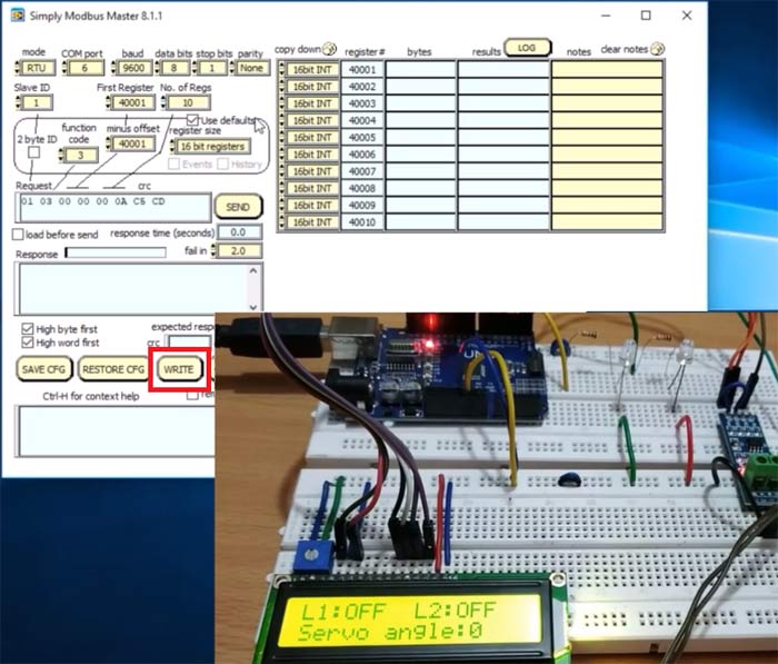
Open the device manager and check the COM port according to your PC where the USB to RS-485 Module is connected and after that open the Simply Modbus Master 8.1.1 software.
1. After Simply Modbus Software is opened now open the Write option.
2. After the Simply Modbus Master Write is opened. Set the parameters
Mode in RTU, COM port according to your PC (mine was COM6), Baud at 9600, Data Bits 8, Stop bit 1, Parity None and Slave ID as 1.
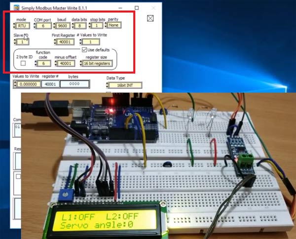
3. After that set first register as 40001 and values to write is 3 and the function code as 16 (Write Holding Register).
After that write 1 to 40001 (For LED1 on) and 1 to 40002 (For LED2 on) and 90 to 40003 (For Servo Motor Angle) and then click SEND button.
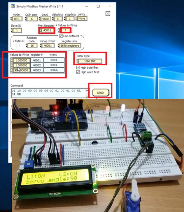
You can see both LED status is ON and servo angle at 90 degree.
4. After that enter 40001 as 1 and 40002 as 0 and 40003 as 180 and click SEND button.
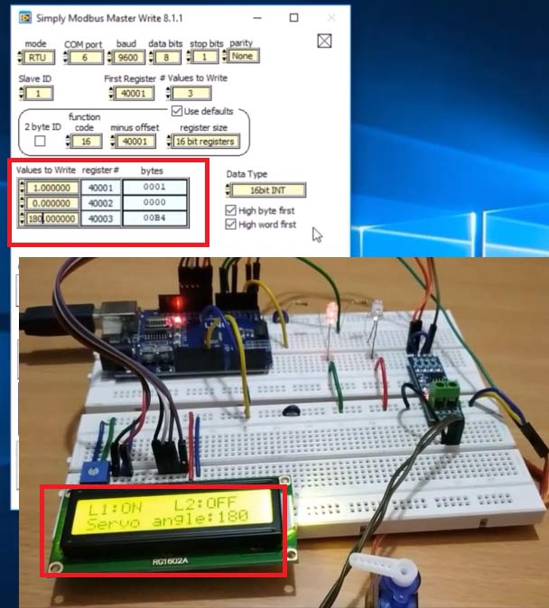
Now Servo angle at 180 and the led1 is ON and led2 is OFF.
5. Now writing 135 to 40003 and 40001 as 0 and 40002 as 1.
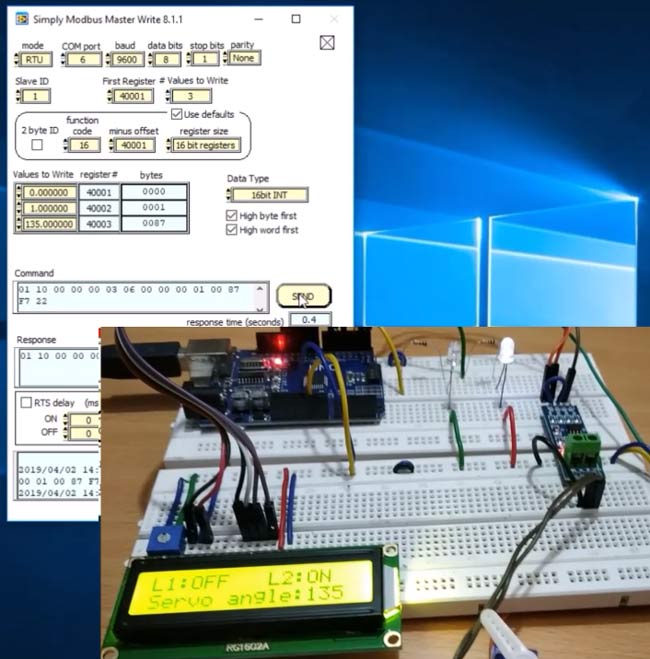
Now the servo position is at 135 and led1 is OFF and led2 is ON.
This is how RS-485 Modbus can be used in serial communication with Arduino UNO as Slave. In next tutorial we will use the Arduino Uno as master in MODBUS commination.
Find the complete code and a Demonstration video below.
Complete Project Code
//RS-485 Modbus Slave (Arduino UNO)

//Circuit Digest
#include<ModbusRtu.h>       //Library for using Modbus in Arduino

#include<LiquidCrystal.h>   //Library for using 16x2 LCD display

#include <Servo.h>          //Library for using Servo Motor
#define led1 2              //Define as 2 led1

#define led2 5              //Define as 5 led2
LiquidCrystal lcd(8,9,10,11,12,13);   //initizlize lcd object with pins (RS,E,D4,D5,D6,D7) for class liquid crystal

Servo servo;                          //Initilize servo object for class Servo

Modbus bus;                          //Define Object bus for class modbus

uint16_t modbus_array[] = {0,0,0};    //Array initilized with three 0 values


void setup()

{

  lcd.begin(16,2);                //Lcd set in 16x2 mode

  lcd.print("RS-485 Modbus");     //Welcome Message

  lcd.setCursor(0,1);

  lcd.print("Arduino Slave");

  delay(5000);

  lcd.clear();


  pinMode(led1,OUTPUT);           //Led1 set as OUTPUT

  pinMode(led2,OUTPUT);           //Led2 set as OUTPUT

  servo.attach(6);                //Servo PWM pin 6

  bus = Modbus(1,1,4);            //Modbus slave ID as 1 and 1 connected via RS-485 and 4 connected to DE & RE pin of RS-485 Module

  bus.begin(9600);                //Modbus slave baudrate at 9600

}
void loop()
{

   bus.poll(modbus_array,sizeof(modbus_array)/sizeof(modbus_array[0]));       //Used to receive or write value from Master


  if (modbus_array[0] == 0)    //Depends upon value in modubus_array[0] written by Master Modbus

  {

    digitalWrite(led1,LOW);    //LED OFF if 0

    lcd.setCursor(0,0);

    lcd.print("L1:OFF");

  }

  else

  {

     digitalWrite(led1,HIGH);  //LED ON if value other than 0

     lcd.setCursor(0,0);

     lcd.print("L1:ON");

  }
 if (modbus_array[1] == 0)    //Depends upon value in modbus_array[1] written by Master Modbus

  {

    digitalWrite(led2,LOW);   //LED OFF if 0

    lcd.setCursor(8,0);

    lcd.print("L2:OFF");

  }

  else

  {

     digitalWrite(led2,HIGH);  //LED ON if value other than 0

     lcd.setCursor(9,0);

     lcd.print("L2:ON");

  }


  int pwm = modbus_array[2]; //Depends upon value in modbus_array[1] written by Master Modbus


  servo.write(pwm);          //Write Received value (0 to 180) from Modbus Master

  lcd.setCursor(0,1);

  lcd.print("Servo angle:");

  lcd.print(pwm);              //Prints Angle in 16x2 LCD display.

  delay(200);

  lcd.clear();

}
Comments
Hi Ameeth, Did you find how to read and write in the same time ? Thank you
Hello Pramoth,
thanks for your posts about the master and slave. I had fun testing your systems! I and some others surely want to push it one step further. Is it possible to include one master and multiple slave devices in one RS485 network?
Previosly I worked with a pre setup professional Modbus system that containd one communication module, one output module and one input module. The communication module sent requests to the input and output modules.
Can I configure the DIY system specified as follows:
- Communication Arduino Nano as the master (ID0) transmitts requests and responds
- The Master sends a request to a slave and waits for a reply
- After the reply the the response is processed and sent to a application interface
- No error report is needed
- Output Arduino Nano as Slave1 (ID1) responds to "Read Input Register" (FC04) to the Master (ID0)
- The Slave checks the request and processes the required action
- No error report is needed
- Input Arduino Nano as Slave2 (ID2) responds to "Write Single Register" (FC06) to the Master (ID0)
- The Slave checks the request and processes the required action
- No error report is needed
I faced some problems when implementing your master and slave approaches into one system
- How to use the libraries in wholistic way, or in the best case, only to use one library?
- How to properly wire the physical layer: Which DI, DE, RE and RO go to which Arduino?
- How to configure the DE and RE pins? Which are enabled?
- How to deal with preTransmission() and postTransmission() (ModbusMaster.h)?
- How to access the different IDs and registers from one Master?
- Your Modbus Master explictly uses writeSingleRegister() to addresses specifed via the Arduino code
- Your Modbus Slave writes Outputs to addresses arbitrarily specified via the ModbuSimply Modbus Master tool. The addresses have not been defined on the slave device in the Arduino code. The polls the uint16_t array modbus_array with poll(). How can we better understand the poll() function? Or even better how can we define addresses that can be recognized by the application interface?
- Display the stream over one Port (trhough the communcation module) and use a application interface (e.g. Simply Modbus Master, ModbusServerPro, Pymodbus, or whatever)
Did you try to build a system like this on your own or has anybody helpful suggestions? I like to share my thoughts with you.
I got a "half working" system that read and wrote data. My ModbusServerPro software indicated read and write access. The reads through the potentiometer were well displayed but the LED randomly went on and off. I guess the data was stored in a not well defined memory location through TX and RX due to code misinterpretation.
Thanks a lot!
Chris
Christopher Can I have you email ID or conatct number.
I try to do this project but failed ...need some help from you
i have to prepare more then 2 same arduino UNO it presented in this tutorial right?
and i put port number one by one?
after, send message and done?
I get Error-1073807339 ocurred at write in SIMM write 8.0vi->SMM 8.0vi
possible reasons: VISa 0xBFFF0015 time out expired before operation completed.
Well what is going on?
its due to Com port mismatching...check the right com port and redo
hallo, i have a project. i want to communicate arduino with plc using modbus rs485. your post about modbus arduino as slave is running well. but i want to send from arduino (as slave) to plc but i dont know that syntax, can you give a example program to send data? thank you
Why it's must used holding register ?
Hello, it was a great explanation.
I have one doubt about how the modbus-array[] was filled.
Thanks
That is great project, but i can't found the library. Can you give me the library, please?
how to send a broadcast?
I tried this project, make the same circuit and have the same software, but it doesn't work, have someone an idea which problem I have?
Please explain in which section you are facing problem ?
Did your code run sucessfully ? did you properly interface all the componens ?
I have wired the Arduino Uno like the schematic on the picture, have an MAX485 the De & RE Pin are connected to D4, If i will write data via SimpleMosbusMaster to the Arduino uno via the RS485 board i get an error no response, so the Arduino maybe don't get data or don't answer.
Hi
I can't found the library. Can you give me the library, please?
Hi
this is very helfull i tryed and it works.
but my problem is i have to make the same projet on software serial
can you help me please?
I got it working to send data to turn on LEDs. Can you teach me how to slave send data to Simply Modbus Master? I have some sensors on the Slave.
Dear Pramoth,
Many thanks for your explanation and for sharing knowledge with other people. I have a quick question and please see below.
If I write one line or 2 line outputs, the program is running fine. However, if I write a lengthy program, the Modbus connection is not working.
For instance, I wrote a program like this;
if (modbus[0] ==0)
{ digitalWrite (led1, HIGH);
digitalWrite (led1, HIGH);
}
else
{
digitalWrite (led1, HIGH);
digitalWrite (led1, LOW);
delay(3000);
digitalWrite (led1, LOW);
digitalWrite (led1, LOW);
delay(1000);
digitalWrite (led1, LOW);
digitalWrite (led1, HIGH);
delay(3000);
digitalWrite (led1, LOW);
digitalWrite (led1, LOW);
delay(1000);
}
When the Modbus array address: 40000 = 0, then it is communicating. However, when the Modbus array: 40000=1; then it stopped communicating to my PLC.
Any idea?
I look forward to seeing your response, please.
Kind regards,
Mahesh Edla.

hi , i tested both program of arduino RS485 modbus as master and slave communication , great thanks for this project and tutorial ,
but i want to send 16 keys data to simply modbus software as arduino in slave mode but also need recive data
from modbus like LED on OFF cammand and error massage , here in bothe example Arduino as master and arduino as Slave there are differant library and command are used , in hardware in RS 485 module DE and RE pin is short and in master mode not , so i want ask how i can use this project as slave mode but as transreceiver mode , want send digital keys data and receive cammand etc , please suggest.