
The 16-channel 12-bit PWM/Servo Driver, PCA9685, is an ideal module for precise control of multiple PWM outputs that are commonly used to control servos, LEDs, and other devices in applications such as robotics, automation, lighting, and servo motor control. In this project, we will use most of this module’s channels to control the Servo motors. At the same time, we will interact and learn all processes of controlling, interfacing, and coding this module so that you are well aware of the Unique use of this module. The PCA9685 servo motor driver is a 16-channel 12-bit PWM controller that will change the way you control servo motors using Arduino. We will do PCA9685 multiple servo control programming, wiring diagrams, and the implementation of robotics and automation projects.
Table of Contents
Required Components for PCA9685 Arduino Servo Control
Arduino Uno R3
8 * SG90 Servo Motor
PCA9685 16-Channel Module
External 5v-Adaptor
Jumper Wires
Servo Interfacing with Arduino
As you are well aware, Servo motors require PWM pulses to run and control them. The changing Duty Cycle PWM pulse can control the Angle of rotation. The Servo motors have three Wires named: VCC, GND, and PWM, and also a small internal circuitry present inside them.
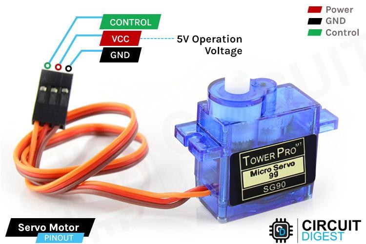
VCC: This wire is used to supply power to the servo motor—the positive voltage source, usually between 4.8V to 6V.
GND: This wire is the ground reference for the servo motor.
Signal (S or PWM): This wire sends control signals to the servo motor, which connects to the PWM (Pulse Width Modulation) output pin on the microcontroller.
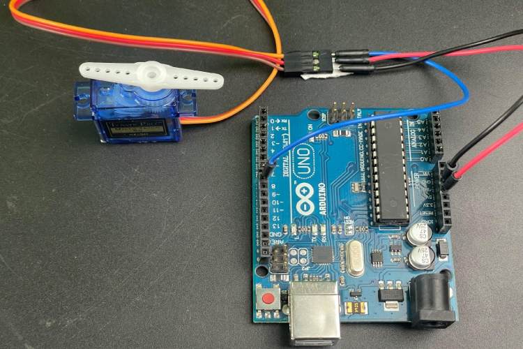
The Connection of the servo with Arduino is pretty simple and only requires three connections:
Connect the VCC and GND of the Servo to 5v and the Ground to the Arduino
Connect any Digital PWM pin to the Servo’s Yellow (PWM) wire.
PCA9685 Servo Driver Quick Reference
| Specification | Details |
| Channels | 16 PWM outputs |
| Resolution | 12-bit (4096 steps) |
| Communication | I2C (SDA, SCL) |
| Default I2C Address | 0x40 |
| Servo Frequency | 50-60 Hz |
| Max Current per Pin | 25mA |
Understanding Servo Motor Basics and Arduino Limitations
The standard Arduino Uno gives only 6 PWM pins, limiting the ability to control multiple servos. Luckily, for projects that use multiple servos, we can present a solution using a PCA9685 servo driver, which will expand to 16 channels using only 2 pins on the Arduino (I2C communication). Then upload the Sweep Sketch from the Servo.h library inside Arduino IDE to make it rotate from 0 to 180 and vice versa.
Moreover, all deep details for understanding servo motors will be provided in the article on How to Control Servo Motor using Arduino
Multi-Servo Interfacing using Arduino
Most of you might have ever used Arduino for any kind of project; it’s a commonly used microcontroller. The Arduino has only six PWM output pins, meaning it can handle only six servos at a time. Let’s say your robot project requires 8 servos to control synchronously the arm’s position. In this case, you need to change the microcontroller, which will cost you even more, and the Controller won’t be fully utilised. And then there are only a few options left other than purchasing a different microcontroller, like:
Using Multiplexing: The technique used to control multiple servos with limited PWM pins. This involves rapidly switching between servos, sending PWM signals to each one in turn. This can be done manually using code, or you can use dedicated ICs like the 74HC595 shift register to expand your PWM outputs. The technique cannot be easily implemented.
Software PWM: Connecting the servos to digital pins on the Arduino and writing code to generate PWM signals on the digital pins using the Arduino IDE will control the servos.
Note: Both of the above methods are quite complex and cannot provide accurate control of servos using PWM. In such a typical condition, the PCA9685 module comes into the Picture.
PCA9685 Servo Driver Pinout and Specifications
PCA9685 module. Compatible with Arduino and Raspberry Pi-like platforms, this module resolves the issue of limited PWM outputs on microcontrollers. By utilising only 2 pins, it enables control of 16 free-running PWM outputs. Understanding the PCA9685 servo driver pinout is crucial for proper PCA9685 Arduino wiring:
Operated through I2C, this PWM driver includes a built-in clock, eliminating the need for continuous signal transmission from the microcontroller. It operates at 5V but remains 3.3V microcontroller-compatible, facilitating safe driving of outputs up to 6V. This feature is beneficial for controlling LEDs with 3.4+ forward voltages, such as white or blue ones.
With 6 address select pins, you can connect up to 62 modules on a single I2C bus, providing 992 outputs.
The module comes with six control pins or Arduino interfacing pins named: VCC, GND, SDA, SCL, OE, and V+. Follow this detailed PCA9685 servo driver wiring diagram for proper PCA9685 Arduino wiring:
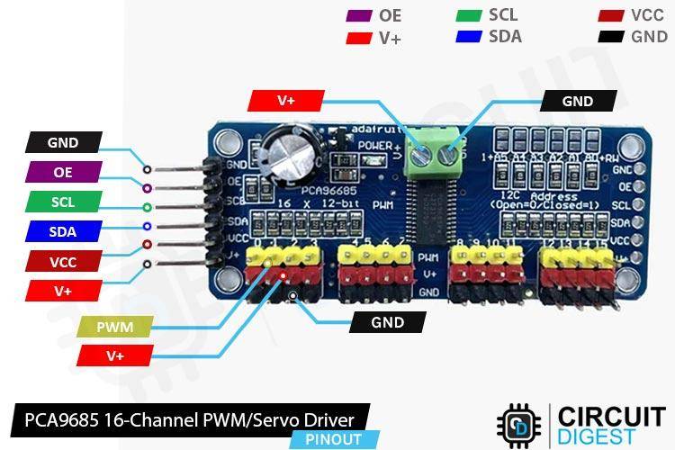
GND: Ground connection.
VCC: Power supply voltage (usually 3.3V to 5V) to power the PCA9685 module internal circuitry.
SDA (Serial Data Line): Connects to the I2C data line on your microcontroller.
SCL (Serial Clock Line): Connects to the I2C clock line on your microcontroller.
OE (Output Enable): Output Enable pin. Pulling this pin low will disable all outputs.
V+ (External Power): The pin on the PCA9685 module typically refers to providing the external power supply voltage for the servos or devices connected to the output channels.
Signal / PWM: The pin used to control the servos by changing the PWM duty cycle.
The Module combines the power of several different features and components, which strengthen its effectiveness and beginner-friendly environment.
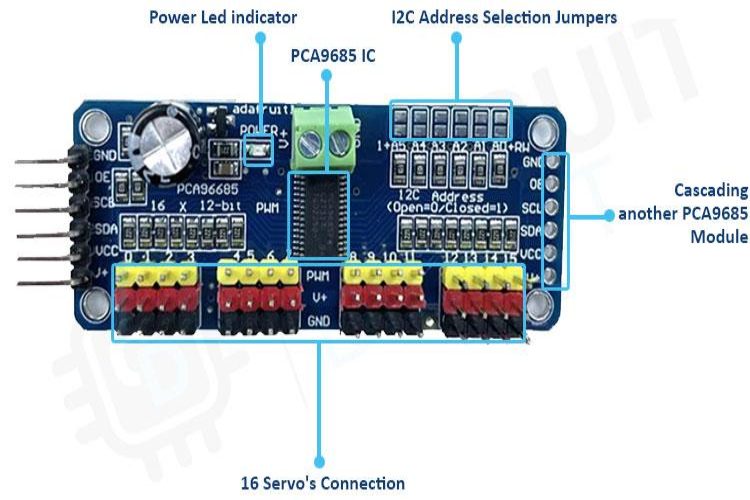
Power LED indicator: The Indicator LED often displays the power status of the module, which is either ON or OFF.
16 Servos' Connection: There are 16 output ports, each equipped with three pins: V+, GND, and a PWM output. While the PWM outputs operate independently, they all need to share the same PWM frequency. For example, LEDs typically require a frequency of 1.0 kHz, while servos need 60 Hz. It's important to note that you cannot allocate half of the ports for LEDs at 1.0 KHz and the other half for servos at 60 Hz. The module is configured for servos, but it can also be utilised for LEDs. The frequency can be set/changed inside the Sketch code, allowing control of 16 particular identical devices at once.
Each PWM pin has a 220-ohm resistor in series, and the output logic aligns with VCC. It's crucial to consider these specifications, especially when dealing with LEDs, given their sensitivity to voltage and current. Additionally, the maximum current per pin is limited to 25mA.
Cascading another PCA9685 Module: The PCA9685 supports I2C communication, and you can cascade multiple PCA9685 modules together on the same I2C bus. All six header pins of the secondary module can be directly attached to the Vacant side pins of the previous module, as you can see in the image below:
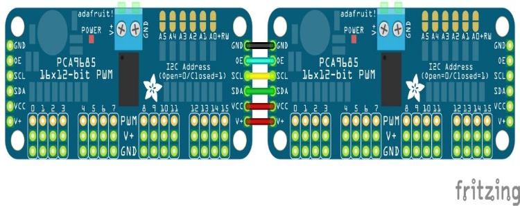
Each PCA9685 module needs to have a unique I2C address to avoid conflicts. The PCA9685 has a few hardware address jumpers (A0, A1, to A5) that you can use to set a different address for each module.
The I2C address is 7 bits, and it's made up of the combination of address bits (A0 to A5) and the RW bit.
The RW bit is the least significant bit (LSB) of the 7-bit address.
If the RW bit is 0, it indicates a write operation. If it's 1, it indicates a read operation.
The different combinations of address bits from A0 to A5 can set a different address for each module. Thus, the PCA9685 supports up to 62 unique addresses (including the default address), so in theory, you can connect up to 62 PCA9685 modules to the same I2C bus, each with a different address. The default I2C address for the PCA9685 is 0x40.
I2C Address Selection Jumpers: You can establish a unique address by configuring the address jumpers located on the upper right edge of the board. The binary address set through these jumpers is then combined with the base I2C address. To set the address offset, use a small amount of solder to connect the appropriate address jumper for each '1' in the binary address.
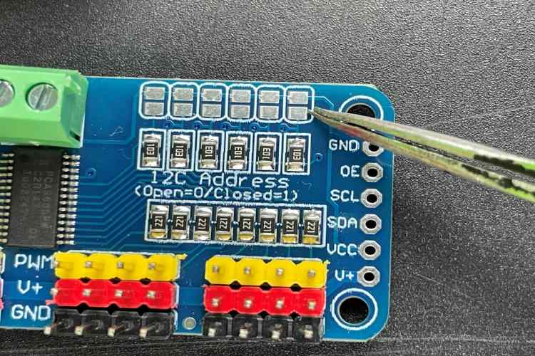
Board 0: Address = 0x40 Offset = binary 00000 (no jumpers required)
Board 1: Address = 0x41 Offset = binary 00001 (bridge A0 as in the photo above)
Board 2: Address = 0x42 Offset = binary 00010 (bridge A1)
Board 3: Address = 0x43 Offset = binary 00011 (bridge A0 & A1)
Board 4: Address = 0x44 Offset = binary 00100 (bridge A2)
etc.
Later you can declare each object for each board inside your code sketch. Initiate the "begin" function for each object, and manage each servo by interacting with the respective object it is connected to.
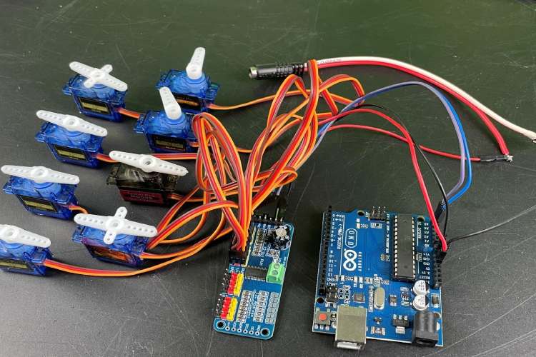
PCA9685 with Arduino Circuit Diagram
We are going to connect eight servo motors to the PCA9685 controller, which is eventually more than the Arduino board's PWM digital pins. Also, currently, we are using only a single controller board, which is enough for eight servos. We use a 5V external adaptor to supply our servos using a V+ pin.

Connect VCC to 5v and GND to the Ground pin of the Arduino.
Connect the external Source positive to the V+ terminal of PCA9685, which is directly connected to Servo VCC. And the ground is common to Arduino Ground.
Connect the SDA and SCL to A4 & A5, respectively, for I2C communication with the module.
Each servo is connected to each channel on the module. Each channel module also has the same three pins: Signal/PWM, V+, and GND, which are identical to the servo.
PCA9685 vs Alternative Servo Control Methods
| Method | Max Servos | Arduino Pins Used | Accuracy | Complexity |
| Direct Arduino PWM | 6 servos | 6 PWM pins | High | Low |
| Software PWM | 12+ servos | All digital pins | Medium | High |
| Shift Register (74HC595) | 8+ servos | 3 pins | Low | Very High |
| PCA9685 I2C | 16+ servos | 2 pins (I2C) | Very High | Low |
PCA9685 Arduino Code: Complete Programming Guide
The code sets the I2C communication with the Controller module and initiates the module to control the servos channel described inside the code. Our code rotates the servos synchronously from 0 to 180 and 180 to 0. This PCA9685 Arduino code demonstrates PCA9685 multiple servo control programming using the Adafruit PWM Servo Driver library:
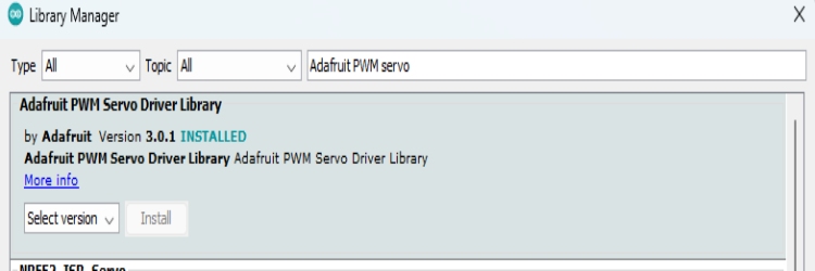
Firstly, we are going to use a library Adafruit_PWMServoDriver.h, which has most of the inbuilt features or functions to make controlling easy. The library can be easily installed using the simple process:
Open Arduino IDE > Tools > Manage Libraries > Search for “Adafruit PWM Servo Driver”, then install it.
The single object created by the library is defined for accessing the single controller board. If you cascade the multiple boards, then you can simply define each object for each board. The I2C address should be passed as a parameter while creating the object, and as we are well aware, the different I2C addresses should be generated for multiple boards.
The values of minimum and Maximum pulses are defined inside two Different variables, which are used to set the rotation angle of the Servos. Minimum and Maximum value defines the 0 and 180 servo angle positions, respectively.
#include <Adafruit_PWMServoDriver.h>
Adafruit_PWMServoDriver board1 = Adafruit_PWMServoDriver(0x40);       // called this way, it uses the default address 0x40
#define SERVOMIN  125                                                 // this is the 'minimum' pulse length count (out of 4096)
#define SERVOMAX  625                                                 // this is the 'maximum' pulse length count (out of 4096)
Inside setup, we began with the Serial monitor, then we called the controller board to begin functioning. If you are using multiple boards, then initialise each one with begin(). Additionally, by using the function setPWMFreq(); we can set the desired frequency to control the different output devices on the 16 channels. Since Servos are very comfortable at 60Hz.
void setup() {
  Serial.begin(9600);
  Serial.println("16 channel Servo test!");
  board1.begin();
  board1.setPWMFreq(60);                  // Analog servos run at ~60 Hz updates
}
Inside the loop, the function setPWM() is used, which takes three parameters as input, and it is also used to set the pulse width for a specific channel on the PCA9685 PWM driver. Here's the function signature:
void Adafruit_PWMServoDriver::setPWM(uint8_t num, uint16_t on, uint16_t off);num: The channel number (0 to 15) on the PCA9685 for which you want to set the PWM values.
On: The "on" time, which is the tick (counter value) when the signal should transition from low to high.
Off: The "off" time, which is the tick (counter value) when the signal should transition from high to low.
The two for loops are used, in which the first one sets the Zeroth position for all the servos. The secondary For loop synchronously sweeps all 8 channels from 0 to 180 degrees.
void loop()
  { for(int i=0; i<8; i++)
      { board1.setPWM(i, 0, angleToPulse(0) );}
    delay(1000);

    for( int angle =0; angle<181; angle +=10)
      { for(int i=0; i<8; i++)
          { board1.setPWM(i, 0, angleToPulse(angle) );}
      }
    delay(100);
  }
Finally, a simple function is defined which takes the angle value and returns the pulse value by mapping both the Min and Max values.
int angleToPulse(int ang)                             //gets the angl	e in degree and returns the pulse width
  {  int pulse = map(ang,0, 180, SERVOMIN,SERVOMAX);  // map angle of 0 to 180 to Servo min and Servo max
     Serial.print("Angle: ");Serial.print(ang);
     Serial.print(" pulse: ");Serial.println(pulse);
     return pulse;
  }
That’s how our code sweeps the servos back & and forth from 0 to 180 degrees.
Note: If you are using more channels on the PCA controller, then update the “I” value limit in both for loops up to the updated channel number.
Demonstration of PCA9685 with Arduino
Check for all the connections once before you power it. Attach only eight servos from channels 0 to 7 as mentioned on the controller board. Use an external adapter since Arduino isn’t capable of delivering that much power. All data about angle and pulse are monitored on a serial display. The following demonstration shows synchronised servo movement using the PCA9685 Arduino code:
Troubleshooting Common PCA9685 Issues
- Servos fail to operate: Verify the external power supply connection to V+
- Erratic servo operation: Check for appropriate grounding between the Arduino and PCA9685
- I2C communication errors: Check the SDA/SCL connections (A4/A5 on Uno)
- Insufficient power: Use a dedicated 5V adapter for the servo power supply
- Servo jitter: Change the SERVOMIN/SERVOMAX values for your servos
Technical Summary and GitHub Repository
The Technical Summary highlights the design, operation, and implementation of the project. Our GitHub Repository provides complete source code, schematic diagrams, and detailed documentation of the project. These two components will allow for understanding, repetition, and additional customisation for learners and developers alike.


Conclusion
The PCA9685 servo motor driver is an amazing option for multiple servo control projects with Arduino. The 16-channel PWM output, I2C communication, and ability to cascade multiple drivers provide flexibility and power for future robotics projects while keeping the code simple. This guide has covered everything from wiring the PCA9685 to Arduino to programming PCA9685 multiple servo control projects. You will be set up for success in performing your own servo control projects.
Frequently Asked Questions About PCA9685 Servo Motor Driver
⇥ Q1: What is the PWM frequency for servo control?
Standard servos are designed to operate best at a PWM frequency of about 50-60Hz. Most servo applications can be programmed using setPWMFreq (60). Other devices like LEDs may require PWM frequencies as fast as 1000Hz.
⇥ Q2: How can I calibrate servo positions with the PCA9685?
You will need to experiment with several possible SERVOMIN (normally in the range of about 125) and the value you set for SERVOMAX (also in the range of 625). You should test with your servos and adjust the constants to achieve (or closely approach) the 0° and 180° positions.
⇥ Q3: Can I control different types of servos at the same time with a PCA9685?
Yes, the PCA9685 allows you to potentially control standard servos, micro servos, and continuous rotation servos simultaneously! All of the channels share the same PWM frequency, so ensure you select settings that work with all servos connected to it.
⇥ Q4: Which library do I need to program the PCA9685 for Arduino?
Use the library "Adafruit PWM Servo Driver" and you will have to install the library via the Arduino IDE Library Manager. The library has simple functions like setPWM(), setPWMFreq(), and begin() that will make controlling the PCA9685 easy.
⇥ Q5: What causes PCA9685 servo jitter or instability, and how do I debug/fix it?
The most common issues that cause servo jitter are a weak power supply, poor ground, or wrong values for pulse width. Make sure that you have supplied a stable 5V power supply to the servo, that your ground is from a common point, and that the SERVOMIN/SERVOMAX values are correct.
⇥ Q6: What is the maximum current draw on each PCA9685 channel?
There is a maximum current of 25mA on each channel of the PCA9685. When controlling the servo, this current looks at only the signal line, as the power comes from the external V+ connection.
Applications of PCA9685 in Real Projects
Explore our earlier projects featuring the PCA9685 module through the links provided below.

How to Control Servo Motor using Arduino
This step-by-step guide will help you understand the fundamentals of servo motor control and how to integrate it with an Arduino for your projects. After you have learned the basics you can try other Arduino servo motor projects like this robotic arm using servo motor. You can also find other such Arduino tutorials and projects on our website.

Edge AI On Quadruped Robot Dog using Maixduino Development Kit
The project showcases the integration of edge AI and robotics into a quadruped robot platform, demonstrating the growing accessibility of embedding intelligent features into physical devices.

An AI-Driven Tofu Flipping System Using Arduino Mega for Smart Cooking Automation
For tofu detection, the system employs YOLOv8-based AI, trained on 1,675 tofu images using the Roboflow platform. Once detected, the system calculates the tofu’s coordinates relative to the camera and guides the robotic arm accordingly.
Complete Project Code
#include <Adafruit_PWMServoDriver.h>
Adafruit_PWMServoDriver board1 = Adafruit_PWMServoDriver(0x40);       // called this way, it uses the default address 0x40
#define SERVOMIN  125                                                 // this is the 'minimum' pulse length count (out of 4096)
#define SERVOMAX  625                                                 // this is the 'maximum' pulse length count (out of 4096)
void setup() {
  Serial.begin(9600);
  Serial.println("16 channel Servo test!");
  board1.begin();
  board1.setPWMFreq(60);                  // Analog servos run at ~60 Hz updates
}
void loop()
  { for(int i=0; i<8; i++)
      { board1.setPWM(i, 0, angleToPulse(0) );}
    delay(1000);

    for( int angle =0; angle<181; angle +=10)
      { for(int i=0; i<8; i++)
          { board1.setPWM(i, 0, angleToPulse(angle) );}
      }
    delay(100);
  }
int angleToPulse(int ang)                             //gets angle in degree and returns the pulse width
  {  int pulse = map(ang,0, 180, SERVOMIN,SERVOMAX);  // map angle of 0 to 180 to Servo min and Servo max
     Serial.print("Angle: ");Serial.print(ang);
     Serial.print(" pulse: ");Serial.println(pulse);
     return pulse;
  }
Comments
The PCA9685 doesn't provide the power for the motor. It only provides the control signal. So there won't be any damage to the chip its self.
No it wont, there is a difference between providing control signal and sourcing power
I finally got mine to work! I had been trying several 5 volt power supplies with no luck, I finally tried a nine volt power supply, hooked up the way it is in your diagram, and it worked. It doesn't work if I use the green power block, only if I provide power through the V+ with the 9 volt power supply. I'm assuming it was the amps and not the volts, but I'm going to troubleshoot more.

If multiple 16 kgcm motors operate at same time the PCA9685 will only end up in smokes almost instantly.