
ESP8266 Wi-Fi transceiver provides a way to connect a microcontroller to the network. It is widely used in IoT projects as it is cheap, tiny and easy to use. We have previously used it to create webserver using Raspberry webserver and Arduino webserver.
In this tutorial we will interface an ESP8266 Wi-Fi Module with the ARM7-LPC2148 microcontroller and create a webserver to control the LED connected to LPC2148. The workflow will go like this:
- Send AT commands from LPC2148 to ESP8266 to configure ESP8266 in AP mode
- Connect the laptop or computer Wi-Fi with the ESP8266 Access point
- Create a HTML webpage in PC with Access point IP address of the ESP8266 webserver
- Create a program for LPC2148 to control the LED according to the value received from ESP8266
If your completely new to ESP8266 Wi-Fi module visit the below links to get familiar with ESP8266 Wi-Fi module.
- Getting Started with ESP8266 Wi-Fi Transceiver (Part 1)
- Getting Started with ESP8266 (Part 2): Using AT Commands
- Getting Started with ESP8266 (Part 3): Programming ESP8266 with Arduino IDE and Flashing its Memory
Components Required
Hardware:
- ARM7-LPC2148
- ESP8266 Wi-Fi Module
- FTDI (USB to UART TTL)
- LED
- 3.3V Voltage Regulator IC
- Breadboard
Software:
- KEIL uVision
- Flash Magic Tool
- Putty
ESP8266 Wi-Fi module
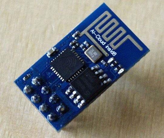
ESP8266 is a low cost widely used Wi-Fi module for embedded projects which requires a low power of 3.3V. It uses only two wires TX and RX for serial communication and data transfer between ESP8266 and any microcontroller having UART port.
Pin Diagram for ESP8266 Wi-Fi module
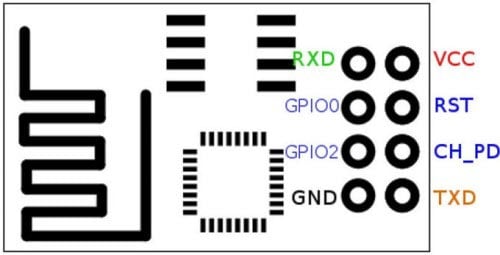
- GND, Ground (0 V)
- TX, Transmit data bit X
- GPIO 2, General-purpose input/output No. 2
- CH_PD, Chip power-down
- GPIO 0, General-purpose input/output No. 0
- RST, Reset
- RX, Receive data bit X
- VCC, Voltage (+3.3 V)
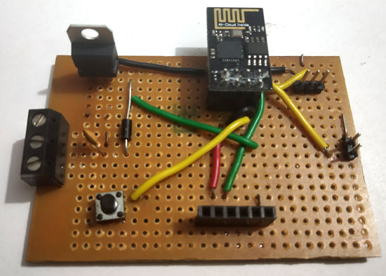
Setting up ESP8266 Circuit Board
ESP8266 requires a constant supply of 3.3V and it is not breadboard friendly. So in our previous tutorial on ESP8266, we made a circuit board for ESP8266 with 3.3V Voltage regulator, a RESET push button and jumper setup for switching modes (AT command or flash mode). It can also be setup on breadboard without using perf board.
Here we soldered all the components on breadboard to make our own ESP8266 Wi-Fi board
Learn interfacing of ESP8266 with various microcontrollers by following below links:
- Getting Started with ESP8266 (Part 3): Programming ESP8266 with Arduino IDE and Flashing its Memory
- Connecting ESP8266 with STM32F103C8: Creating a Webserver
- Sending Email Using MSP430 Launchpad and ESP8266
- Interfacing ESP8266 with PIC16F877A Microcontroller
- IOT Based Dumpster Monitoring using Arduino & ESP8266
All the ESP8266 based projects can be found here.
Connecting LPC2148 with ESP8266 for Serial Communication
In order to interface ESP8266 with LPC2148 we must establish a UART serial communication between these two devices to send AT commands from LPC2148 to ESP8266 to configure the ESP8266 Wi-Fi module. To know more about ESP8266 AT commands follow the link.
So in order to use UART communication in LPC2148 we need to initialize UART port in LPC2148. LPC2148 has two inbuilt UART ports (UART0 and UART1).
UART Pins in LPC2148
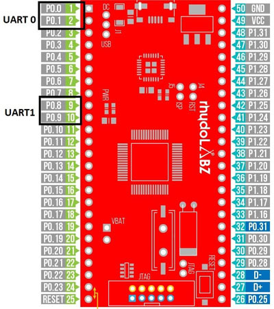
UART_Port | TX_PIN | RX_PIN |
UART0 | P0.0 | P0.1 |
UART1 | P0.8 | P0.9 |
Initializing UART0 in LPC2148
As we know that the pins of LPC2148 are general purpose pins so we need to use PINSEL0 register for using UART0. Before initializing UART0 lets know about these UART registers used in LPC2148 for using UART feature.
UART Registers in LPC2148
The table below shows some important registers used in programming. In our future tutorials we will see briefly about other registers used for UART in LPC2148.
x-0 for UART0 & x-1 for UART1:
REGISTER | REGISTER NAME | USE |
UxRBR | Receive Buffer Register | Contains Recently Received Value |
UxTHR | Transmit Holding Register | Contains Data to be transmitted |
UxLCR | Line Control Register | Contains UART frame format (No of Data Bits, Stop bit) |
UxDLL | Divisor Latch LSB | LSB of UART baud rate generator value |
UxDLM | Divisor Latch MSB | MSB of UART baud rate generator value |
UxIER | Interrupt Enable Register | It is used to enable UART0 or UART1 interrupt sources |
UxIIR | Interrupt Identification Register | It contains the status code that has priority and source of pending interrupts |
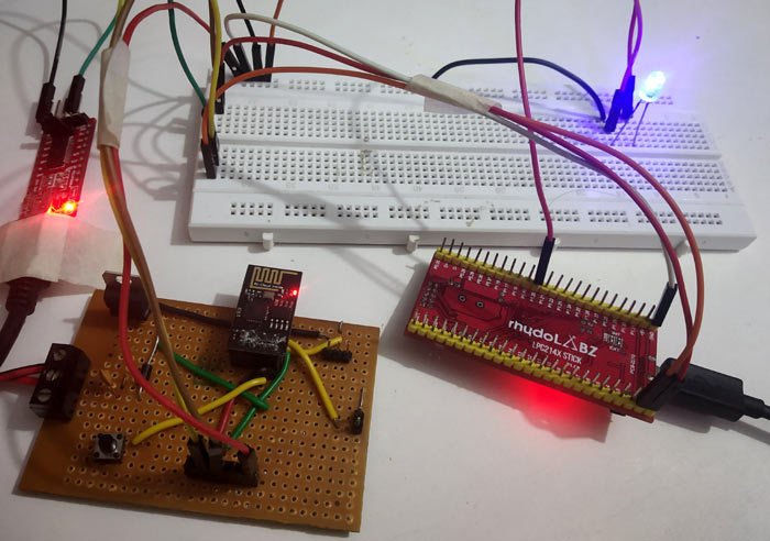
Circuit Diagram and Connections

Connections between LPC2148, ESP8266 and FTDI is shown below
LPC2148 | ESP8266 | FTDI |
TX (P0.0) | RX | NC |
RX(P0.1) | TX | RX |
ESP8266 is powered via a 3.3V voltage Regulator and FTDI & LPC2148 are powered from USB.
In this tutorial we have connected the RX pin of FTDI (USB to UART TTL) to the ESP8266 TX pin which is further connected to LPC2148 RX pin, so that we can see the response of ESP8266 module using any terminal software like putty, Arduino IDE. But for that set the baud rate as according to baud rate of ESP8266 Wi-Fi module. (My Baud Rate is 9600).
Steps involved in programming UART0 in LPC2148 for interfacing ESP8266
Below are the programming steps to connect ESP8266 with LPC2148 which will make it IoT compatible.
Step 1:- First we need to initialize the UART0 TX & RX pins in the PINSEL0 register.
(P0.0 as TX and P0.1 as RX)
PINSEL0 = PINSEL0 | 0x00000005;
Step 2:- Next in U0LCR (Line Control Register), set the DLAB (Divisor Latch Access Bit) to 1 as it enables them and then set no of stop bits as 1 and data frame length of 8-bit.
U0LCR = 0x83;
Step 3:- Now important step to be noted is to set the values of U0DLL & U0DLM depending upon the PCLK value and the desired baud rate. Normally for ESP8266 we use baud rate of 9600. So let’s see how to set 9600 baud rate for UART0.
Formula for baud rate calculation:

Where,
PLCK: Peripheral Clock in Frequency (MHz)
U0DLM, U0DLL: Baud Rate generator divider registers
MULVAL, DIVADDVAL: These registers are fraction generator values
For Baud Rate 9600 with PCLK=15MHZ

MULVAL =1 & DIVADDVAL=0
256*U0DLM+U0DLL=97.65
So U0DLM=0 and we get U0DLL=97 (Fraction not allowed)
So we use following code:
U0DLM = 0x00;
U0DLL = 0x61; (Hexadecimal value of 97)
Step 4:- Finally, we must make DLA (Divisor Latch Access) disable set to 0 in LCR.
So we have
U0LCR &= 0x0F;
Step 5:- For Transmitting a Character, load the byte to be sent in U0THR and wait until the byte is transmitted, which is indicated by the THRE becoming HIGH.
void UART0_TxChar(char ch)
{
                U0THR = ch;
                while( (U0LSR & 0x40) == 0 );
}
Step 6:- For Transmitting a String, below function is used. To send string data one by one we used the character function from above step.
void UART0_SendString(char* str)
{
                uint8_t i = 0;
                while( str[i] != '\0' )
                {
                                UART0_TxChar(str[i]);
                                i++;
                }
}
Step 7:- For Receiving a string, interrupt service routine function is used here because an ESP8266 Wi-Fi module will transmit data back to the RX pin of LPC2148 whenever we send AT command or whenever an ESP8266 sends data to LPC2148, like we send data to a webserver of ESP8266.
Example: When we send AT command to ESP8266 from LPC2148 (“AT\r\n”) then we get a reply “OK” from the Wi-Fi module.
So we use an interrupt here to check the value received from the ESP8266 Wi-Fi module as the ISR interrupt service routine has the highest priority.
So whenever an ESP8266 sends data to RX pin of LPC2148 the interrupt is set and ISR function gets executed.
Step 8:- To enable interrupts for UART0, use following code
The VICintEnable is vectored interrupt enable register used to enable interrupt for UART0.
VICIntEnable |= (1<<6);
The VICVecCnt10 is vectored interrupt control register that allocates slot for UART0.
VICVectCntl0 = (1<<5) | 6;
Next the VICVectaddr0 is vectored interrupt address register that has the interrupt service routine ISR address.
VICVectAddr0 = (unsigned) UART0_ISR;
Then we have to assign the interrupt for RBR Receive buffer register. So in Interrupt enable register (U0IER) we set for RBR. So that interrupt service routine (ISR) is called when we receive data.
U0IER=IER_RBR;
Finally, we have the ISR function that needs to do certain task when we receive data from ESP8266 Wi-Fi Module. Here we just read the received value from the ESP8266 that is present in the U0RBR and store those value in the UART0_BUFFER. Finally at the end of ISR the VICVectAddr should be set with zero or dummy value.
            void UART0_ISR() __irq
{
                unsigned char IIRValue;

                IIRValue = U0IIR;

                IIRValue >>=1;
                IIRValue&=0x02;
                if(IIRValue == IIR_RDA)
                {
                                UART_BUFFER[uart0_count]=U0RBR;
                                uart0_count++;
                                if(uart0_count == BUFFER_SIZE)
                                {
                                                uart0_count=0;
                                }
                }
                VICVectAddr = 0x0;
}
Step 9:- As ESP8266 Wi-Fi module should be set in the AP mode, we need to send the respected AT commands from LPC2148 by using the UART0_SendString() function.
The AT commands which are sent to ESP8266 from LPC2148 are mentioned below. After sending each AT command ESP8266 responds with “OK”
1. Sends AT to ESP8266
UART0_SendString("AT\r\n");
delay_ms(3000);
2. Sends AT+CWMODE=2 (Setting ESP8266 in AP mode).
UART0_SendString("AT+CWMODE=2\r\n");
delay_ms(3000);
3. Sends AT+CIFSR (For getting IP of AP)
UART0_SendString("AT+CIFSR\r\n");
delay_ms(3000);
4. Sends AT+CIPMUX=1 (For Mutliple Connections)
UART0_SendString("AT+CIPMUX=1\r\n");
delay_ms(3000);
5. Sends AT+CIPSERVER=1,80 (For ENABLING ESP8266 SERVER with OPEN PORT)
UART0_SendString("AT+CIPSERVER=1,80\r\n");
delay_ms(3000);
Programming and Flashing Hex File to LPC2148
To Program ARM7-LPC2148 we need keil uVision & Flash Magic tool. A USB Cable is used here to program ARM7 Stick via micro USB port. We write code using Keil and create a hex file and then the HEX file is flashed to ARM7 stick using Flash Magic. To know more about installing keil uVision and Flash Magic and how to use them follow the link Getting Started With ARM7 LPC2148 Microcontroller and Program it using Keil uVision.
Complete program is given at the end of the tutorial.
Note: While uploading HEX file to LPC2148 you must not power the ESP8266 Wi-Fi Module and the FTDI module that is connected with LPC2148.
Controlling the LED using ESP8266 IoT Webserver with LPC2148
Step 1:- After uploading HEX file to LPC2148, connect the FTDI module to PC via USB cable and open the putty terminal software.
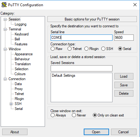
Select Serial and then Select the COM port according to your PC or LAPTOP mine was (COM3). The baud rate is 9600.
Step 2:- Now reset the ESP8266 Wi-Fi Module or just POWER OFF and POWER ON it again, the putty terminal will show the response of the ESP8266 Wi-Fi module as shown below.\
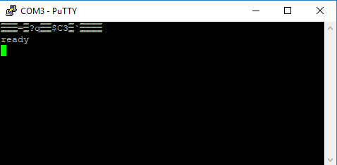
Step 3:- Now press RESET button on the LPC2148. After that LPC2148 begins to send AT commands to ESP8266. We can see the response of that in the putty terminal.
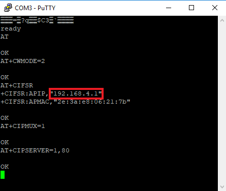
Step 4:- As you can see in the image above the ESP8266 is set in MODE 2 that is AP mode and the address of APIP is 192.168.4.1. Note this address because this address will be hard coded in the webpage HTML code to control the LED connected to LPC2148.
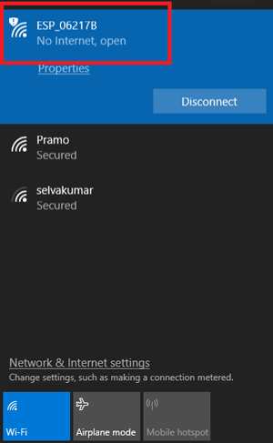
Important: When ESP8266 is in AP mode you must connect your PC to the ESP8266 AP. See the image below my ESP8266 module shows AP in the name of ESP_06217B (It is open and has no password).
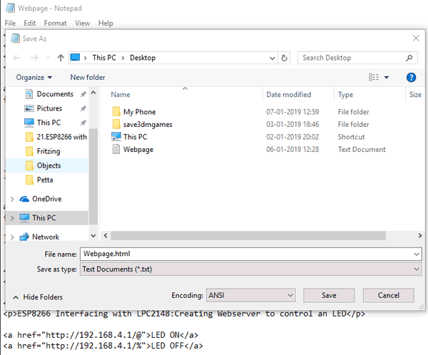
Step 5:- After connecting the PC to the ESP8266 AP, open a notepad and copy-paste the following HTML programme webpage. Make sure to change the APIP address according to your ESP8266 Wi-Fi module
<!DOCTYPE html>
<html>
<body>
<style>
a:link, a:visited
{
background-color: #f44336;
color: white;
padding: 14px 25px;
text-align: center;
text-decoration: none;
display: inline-block;
}
a:hover, a:active
{
background-color: black;
}
</style>
<body>
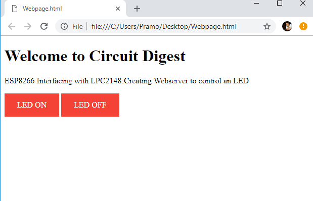
<h1>Welcome to Circuit Digest</h2>
<p>ESP8266 Interfacing with LPC2148:Creating Webserver to control an LED</p>
<a href="http://192.168.4.1/@">LED ON</a>
<a href="http://192.168.4.1/%">LED OFF</a>
</body>
</html>
In this HTML page, we have created two hyperlinked buttons to Turn on and off the LED from webpage.
Finally save the notepad document as .html extension
The webpage will be shown as below in the web browser.
Here the address is the AP IP address 192.168.4.1 and we send values @ and % to switch ON and OFF the LED by using this logic below in LPC2148.
while(1)
{
  if(uart0_count !=0)
     {
             COMMAND[0]=UART0_BUFFER[uart0_count-1];
            if(COMMAND[0] == LEDON)     //Logic to set LED ON or OFF depending upon the received value from ESP8266
                            {
                                      IOSET1=(1<<20);                    //Sets OUTPUT HIGH
                                      delay_ms(100);
                                             }
              else if(COMMAND[0]==LEDOFF)
                                            {
                                                     IOCLR1=(1<<20);                   //Sets OUTPUT LOW
                                     delay_ms(100);

                                            }
                        }
                  }
This is how a device can be controlled remotely using ESP8266 and ARM7 microcontroller LPC2148. Complete code and explanation video is given below.
Complete Project Code
#include <lpc214x.h>
#include <stdint.h>

#define IER_RBR  0X01
#define IIR_RDA  0X02
#define BUFFER_SIZE 0X40

unsigned char UART0_BUFFER[BUFFER_SIZE];
unsigned int  uart0_count;
unsigned char COMMAND[1];

unsigned char LEDON='@',LEDOFF='%';

void UART0_ISR() __irq                        //ISR Interrupt Service Routine Function
{
unsigned char IIRValue;

IIRValue = U0IIR;

IIRValue >>=1;
IIRValue&=0x02;
if(IIRValue == IIR_RDA)
{
UART0_BUFFER[uart0_count]=U0RBR;
uart0_count++;
if(uart0_count == BUFFER_SIZE)
{
uart0_count=0;
}

}
VICVectAddr = 0x0;
}

void delay_ms(uint16_t j)                    // Function for delay in milliseconds
{
    uint16_t x,i;
for(i=0;i<j;i++)
{
    for(x=0; x<6000; x++);                // loop to generate 1 millisecond delay with Cclk = 60MHz
}
}

void UART0_initilize(void)
{
VPBDIV = 0x00;
PINSEL0 = PINSEL0 | 0x00000005;        // Enable UART0 Rx0 and Tx0 pins of UART0
    U0LCR = 0x83;                          // DLAB = 1, 1 stop bit, 8-bit character length
U0DLM = 0x00;                        // For baud rate of 9600 with Pclk = 15MHz
U0DLL = 0x61;                         // We get these values of U0DLL and U0DLM from formula
U0LCR &= 0x0F;                        // DLAB = 0

VICIntEnable |= (1<<6);              //To enable UART0 interrupt
VICVectCntl0 = (1<<5) | 6;           //Enable UART IRQ slot
VICVectAddr0 = (unsigned) UART0_ISR; //UART ISR function address
U0IER=IER_RBR;                       //Enable RBR interrupt
}

void UART0_TxChar(char ch)             //A function to send a byte on UART0
{
U0THR = ch;
while( (U0LSR & 0x40) == 0 );        //Wait till THRE bit becomes 1 which tells that transmission is completed
}

void UART0_SendString(char* str)       //A function to send string on UART0
{
uint8_t i = 0;
while( str[i] != '\0' )
{
UART0_TxChar(str[i]);
i++;
}
}


void wifi_sendATcommands(void)
{
delay_ms(5000);
UART0_SendString("AT\r\n");                   //Sends AT to ESP8266
delay_ms(3000);
UART0_SendString("AT+CWMODE=2\r\n");          //Sends AT+CWMODE=2 (Setting ESP8266 in AP mode)
delay_ms(3000);
UART0_SendString("AT+CIFSR\r\n");             //Sends AT+CIFSR (For getting IP of AP)
delay_ms(3000);
UART0_SendString("AT+CIPMUX=1\r\n");          //Sends AT+CIPMUX=1 (For Mutliple Connections)
delay_ms(3000);
UART0_SendString("AT+CIPSERVER=1,80\r\n");    //Sends AT+CIPSERVER=1,80 (For ENABLING ESP8266 SERVER with OPEN PORT)
delay_ms(3000);
}

int main(void)
{

  IODIR1=(1<<20);               //Sets the pin P1.20 as Output Pin
  UART0_initilize();            //Function Call to initilize UART0
  wifi_sendATcommands();        //Function Call to send AT commands to ESP8266

while(1)
{  if(uart0_count !=0)
    {
COMMAND[0]=UART0_BUFFER[uart0_count-1];
if(COMMAND[0] == LEDON)               //Logic to set LED ON or OFF depending upon the received value from ESP8266
{
IOSET1=(1<<20);                    //Sets OUTPUT HIGH
delay_ms(100);
}
else if(COMMAND[0]==LEDOFF)
{
IOCLR1=(1<<20);                   //Sets OUTPUT LOW
delay_ms(100);
}
}
}
}

Sir can you provide proteus