
In this guide, we will create a simple and precise digital clock using the Raspberry Pi Pico RTC DS3231 Module through the Arduino IDE. We will use a 16x2 I²C LCD screen to display the information. Since the screen is small, we will write smart code that changes what is shown on the screen. For a few seconds, it will display the time and date, and then switch to show the temperature.
What You'll Learn:
- Connecting a DS3231 RTC Module to a Raspberry Pi Pico via I²C
- Techniques for properly syncing up a new RTC module with an accurate time source when initially setting the date and time.
- Creating an efficient program that does not disrupt the main program flow while updating LCD display.
- Interfacing the Raspberry Pi Pico RTC DS3231 RTC Module for accurate timekeeping & reliable operation.
This isn't just about making a clock—it's about creating a reliable timekeeping system that you can later use in alarm systems, scheduling tools, or automation controllers.
Related reading: If you're working on cross-platform RTC integrations, also see Interfacing the RTC with Arduino and Interfacing the RTC with ESP32 for extended applications.
Table of Contents
- Understanding the DS3231 RTC Module
- └ Key Features
- └ DS3231 RTC Module Specifications
- DS3231 RTC Module Pin Configuration
- └ Pin Descriptions
- Schematic Diagram
- Setting Up and Time Adjustment
- └ ⇒ Method 1: Auto-Set the Time from Your Computer (Compile-Time Sync)
- └ ⇒ Method 2: Manually Set a Custom Date and Time
- Components Required
- Circuit Diagram
- Complete Arduino Code
- GitHub Repository
- Troubleshooting
Why Choose DS3231 RTC for Raspberry Pi Pico Projects?
If you're building a data logger, an automatic pet feeder, or a reliable desk clock, your system needs to keep track of the exact time, especially when there's no power. That's where the Real-Time Clock (RTC) comes in. There are many RTC options available, but the DS3231 RTC module is usually considered the best choice for both hobbyists and professionals. So why is the DS3231 so special? Older models, like the DS1307, aren't as accurate. They can gain or lose several minutes each month, depending on the temperature. The DS3231 RTC module specification includes a built-in Temperature-Compensated Crystal Oscillator (TCXO). In simple terms, it checks the temperature around it and adjusts how fast it counts time internally. This helps it stay extremely accurate, whether it's in a cold garage or a hot server room.
Understanding the DS3231 RTC Module
The DS3231 RTC module is like a more advanced version of a typical clock chip. Most basic real-time clock (RTC) modules have a problem. They rely on an external crystal to keep time, but crystals are sensitive to temperature changes. When the temperature rises or drops, the crystal vibrates differently, causing the clock to gain or lose time over days or weeks. The DS3231 has a built-in Temperature-Compensated Crystal Oscillator (TCXO) that constantly monitors the temperature and makes small adjustments to keep the time accurate. This means you don’t need to manually fix it. It stays precise whether it’s in a cold or warm environment. The DS3231 is a highly accurate real-time clock and calendar module that tracks seconds, minutes, hours, day, date, month, and year. It also automatically handles leap years.
Key Features for Makers
- The DS3231 is reliable and has a built-in battery compartment, usually for a CR2032 coin battery.
- If your Pico disconnects or there's a power cut, it switches to the battery and continues working without any problems.
- It also includes additional sensors. Because it measures temperature to keep the clock accurate, you can also use the temperature readings for other tasks.
- This chip uses very little power, making it ideal for devices that run on batteries or need to operate for a long time without needing frequent charging.
- The DS3231 is the best choice if your project requires precise timing.
DS3231 RTC Module Specifications
DS3231 RTC Module Pin Configuration
The image below shows the DS3231 RTC module pin configuration.
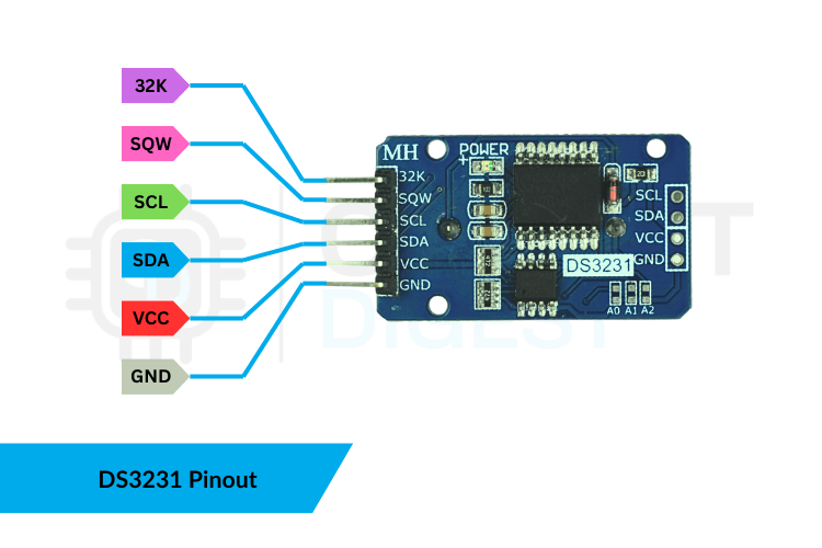
Pin Descriptions
The DS3231 module typically exposes the following pins:
32K - 32K oscillator output.
SQW - Square Wave output pin.
SCL - I²C clock line.
SDA - I²C data line.
VCC - 3.3V / 5V power input (use 3.3V for Pico).
GND - Ground.
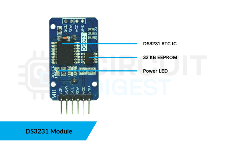
Raspberry Pi Pico RTC DS3231 Module Schematic Diagram
The schematic diagram of the DS323 RTC module is given below.

The Raspberry Pi Pico RTC DS3231 Module has a few basic parts that work together to keep accurate time. The image shows these DS3231 RTC module specifications clearly, so you can understand what each one does on the board.
DS3231 vs DS1307: Which RTC Module to Choose?
When choosing an RTC for your Raspberry Pi Pico RTC project, understanding the differences between DS3231 and DS1307 is crucial. The table below shows the key differences between the DS3231 and the DS1307.
Feature | DS3231 | DS1307 |
| Accuracy | +/- 2ppm (TCXO) | +/- 20–40ppm |
| Temperature Compensation | Yes | No |
| Operating Voltage | 2.3V–5.5V | 4.5V–5.5V |
| Backup Battery | CR2032 | CR2032 |
| Interface | I²C | I²C |
| Drift | Extremely low | High (significantly drifts per month) |
| Temperature Sensor | Yes | No |
DS3231 is the reliable choice in the industry for interfacing the RTC module with Raspberry Pi Pico. DS1307 is outdated for any application that needs accuracy.
Setting Up and Time Adjustment of DS3231 RTC Module
Required Arduino Libraries
You can download the Libraries from the attached GitHub links. These are essential for DS3231 with Pico using Arduino IDE programming.
The DS3231 only needs its time set once when you first set it up. After that, the battery inside keeps the time accurate even if the main power is turned off. There are two practical approaches to setting the time in the Arduino environment when working with the Raspberry Pi Pico RTC DS3231.
⇒ Method 1: Auto-Set the Time from Your Computer (Compile-Time Sync)
This is the most efficient and widely used method. When you add:
rtc.adjust(DateTime(F(__DATE__), F(__TIME__)));The Arduino compiler adds the current date and time from your computer into the code right when you compile it. When you upload this program to the microcontroller, the DS3231 gets a precise time stamp that matches your computer’s clock.
How to do it correctly
1. Enable the line in your code.
2. Upload the sketch right away after compiling to reduce the time between compiling and flashing.
3. After that, comment out the line and upload again.
// rtc.adjust(DateTime(F(__DATE__), F(__TIME__)));If you don't comment out the code, the RTC will reset to the compile time each time the microcontroller starts up, which is a common beginner error and results in incorrect time tracking.
⇒ Method 2: Manually Set a Custom Date and Time
If you need to set a specific date for testing, a scheduled demo, or to sync multiple devices, use the manual method.
rtc.adjust(DateTime(2025, 11, 14, 15, 30, 00));Format
rtc.adjust(DateTime(YEAR, MONTH, DAY, HOUR, MINUTE, SECOND));This method allows you to set a specific time, giving you full control when you need the RTC to match a time that's not the current one. This is useful for tasks like:
- Making sure multiple clocks in a network all show the same time
- Testing when alarms go off
- Creating events that happen based on time
- Going back to a specific time after being away for a long time
Just like with the auto-set method, you upload the sketch once, check that the RTC has been updated, and then remove the command so it doesn't run again by mistake.
Components Required for Interfacing the Raspberry Pi Pico RTC DS3231 Module
To make the digital clock using the DS3231 RTC module interfacing with Raspberry Pi Pico, the following components are used.
| Component | Quantity | Role |
| Raspberry Pi Pico | 1 | Main controller |
| DS3231 RTC Module | 1 | Keeps accurate time even when power is off |
| 16x2 I2C LCD | 1 | Displays the texts |
| Breadboard | 1 | For easy prototyping |
| Jumper Wires | Several | Electrical connections |
| USB Cable | 1 | Uploading code |
| Power Supply Module | 1 | To power Pico and I2C LCD |
Circuit Diagram of Interfacing Raspberry Pi Pico RTC DS3231
The circuit diagram shows the connection of the Interfacing Raspberry Pi Pico RTC DS3231 with a 16x2 I2C LCD.
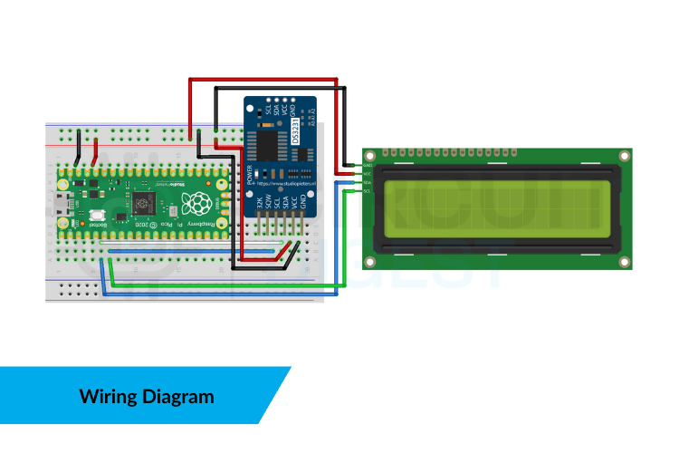
To connect the DS3231 RTC module to the Raspberry Pi Pico and 16x2 LCD, follow the table.
| Raspberry Pi Pico | DS3231 | LCD (16x2, I²C) |
| 3.3V | VCC | VCC |
| GND | GND | GND |
| GP4 | SDA | SDA |
| GP5 | SCL | SCL |
Complete Arduino Code for Raspberry Pi Pico RTC DS3231
The system is set up using I²C. The Pico communicates with both the DS3231 RTC module and the 16×2 LCD through the same two wires, SDA and SCL. That's the great thing about I²C. It allows multiple devices to share the same bus, each with its own unique address. The DS3231 has the address 0x68, and the LCD backpack is at 0x27. This library basically informs the compiler, I’m going to use an RTC and an I²C LCD. This code demonstrates interfacing the RTC module with Raspberry Pi Pico to display time, date, and temperature on a 16x2 I²C LCD:
Library Initialization
#include <Wire.h>
#include "RTClib.h"
#include <LiquidCrystal_I2C.h>#define DS3231_ADDR 0x68
#define LCD_ADDR    0x27
These libraries inform the compiler that we're using an RTC and an I²C LCD for our Raspberry Pi Pico RTC project.
Setup Function
In setup(), you start by initialising the Serial communication, which isn't necessary unless you're planning to use it for debugging, then you begin the I²C communication with Wire.begin(), and you start up the LCD. As soon as the LCD is ready, you check right away if the RTC is responding. If the RTC doesn't respond, the code stops right there. This is a smart approach because there's no sense in continuing without the clock working.
Wire.begin();lcd.begin();lcd.backlight();if (!rtc.begin()) {
 lcd.print("RTC NOT FOUND");
 while (1);
}
Here’s something many beginners overlook: the DS3231 keeps track of time as long as the coin cell battery is working. However, if you use a new module or the battery runs out, it loses power, and the time becomes incorrect. In that case, you check if rtc.lostPower() is true, and if so, you set the current compile-time into the RTC. You only do this once; the time keeps resetting every time the device starts up.
if (rtc.lostPower()) {
 rtc.adjust(DateTime(F(__DATE__), F(__TIME__)));
}
Inside the loop, the Pico gets the current time and the temperature from the DS3231, which is accurate to 0.25°C. Instead of printing raw numbers, you turn them into a 16-character string, which works well with a 16x2 LCD. This makes the display clean and easy to read, and it also stops any old characters from staying on the screen.
Main Loop Function
DateTime now = rtc.now();
float temp = rtc.getTemperature();snprintf(line2, 21, "Date: %04u-%02u-%02u", now.year(), now.month(), now.day());
snprintf(line3, 21, "Time: %02u:%02u:%02u", now.hour(), now.minute(), now.second());
snprintf(line4, 21, "Temp: %.2f C", temp);
In the end, all the formatted lines are sent to the LCD screen at the right row positions. Updating the screen once every second keeps it clear and avoids overworking it.
lcd.setCursor(0,0); lcd.print(line1);
lcd.setCursor(0,1); lcd.print(line2);
lcd.setCursor(0,2); lcd.print(line3);
lcd.setCursor(0,3); lcd.print(line4);
delay(1000);
GitHub Repository
If you want the project files, wiring diagrams, sample videos or ready-made examples stored cleanly in this GitHub repository.


Troubleshooting Errors in Interfacing the RTC Module with Pico
⇒ Issue 1: RTC Resets After Power Cycle
- The CR2032 backup battery might be missing, completely drained, or not installed properly.
- The battery holder's contacts might be dirty or not make a good connection.
- Using a non-rechargeable battery on a module that requires LIR2032 (this is rare, but some cheaper copies might differ).
⇒ Issue 2: LCD Shows Garbled Characters
- The I²C address might be set incorrectly (common addresses are 0x27 or 0x3F).
- The contrast adjustment knob on the I²C backpack might not be properly set.
- The data and clock lines might be connected backwards or not connected at all the time.
- The 16x2 backpack board might be of poor quality, leading to unstable pull-up resistors on the PCF8574.
⇒ Issue 3: RTC Not Detected on I²C Bus
- The SDA or SCL lines might be connected incorrectly or swapped.
- The Pico uses a 3.3V I²C bus, but if the module’s pull-ups are set for 5V, it can cause the bus to fail.
- Long cables or low-quality jumper wires can cause problems.
- The DS3231 board might be faulty or have cold solder joints.
⇒ Issue 4: Significant Time Drift
- Genuine DS3231 chips have very little time drift; if the drift is constant, it’s probably a clone or a DS1307 pretending to be a DS3231.
- Extreme temperatures can affect fake modules that don’t have proper TCXO compensation.
- A weak CR2032 battery can make the oscillator unstable during low-power mode.
Advanced Applications Using DS3231 with Raspberry Pi Pico
Once you've mastered basic DS3231 RTC module interfacing with Raspberry Pi Pico, explore these advanced applications:
» Timestamps for Logger
DS3231 can be equipped with an SD Card module to enable accurate logging of sensor data that is also stamped. This is necessary for monitoring environmental changes, implementing agricultural projects, and using for Research experiments.
» Time-Based Alarm System
Programmable alarms provided by the DS3231 chip can be used to trigger various time-based events. Automated pet feeders, reminding users of when to take medications, and controlling the lights based on time and situations are just a few examples of where you can apply a time-based alarm function.
» Astronomical Clock
A combination of accurate timekeeping from an RTC Module with Liverpool-based software and GPS data with multiple astronomical algorithms will provide the means to determine the exact time of sunrise and sunset, Moon phases, and other important Astronomical Events.
» Power Saving Scheduling for Sleep Mode
The DS3231 has a programmable Square Wave output that can be used to wake a Raspberry Pi Pico from a deep sleep condition, depending on scheduled intervals. This feature dramatically increases battery life in remote monitoring applications.
Frequently Asked Questions About Raspberry Pi Pico RTC DS3231
⇥ 1. What is the I2C address for the DS3231 RTC module?
The I²C address of the DS3231 RTC module is fixed at address 0x68. On the other hand, if your module has an EEPROM component (AT24C32), it is addressed by the address 0x57. These details can, however, be checked by using an I²C Scanner Sketch on your Raspberry Pi Pico.
⇥ 2. What is the accuracy of DS3231 in comparison to DS1307?
The DS3231 is much more accurate, with an accuracy of +/- 2ppm (1 minute per year) using its Temperature-Compensated Crystal Oscillator. The DS1307 has an accuracy of +/- 20-40ppm, which can potentially drift by several minutes each month. When it comes to accuracy in time-keeping projects with Raspberry Pi Pico, DS3231 is the better choice.
⇥ 3. Why does my RTC reset to the incorrect time after a power cycle?
It is commonly encountered in situations where the backup battery in CR2032 is either dead, absent, or incorrectly seated. It is essential to check the orientation and voltage of the battery (should be 3V). It is also important to ensure that the terminals on the battery holder are clean.
⇥ 4. Can I interconnect the Raspberry Pi Pico board with the DS3231 module along with other I2C devices?
Yes. This is because I²C communicates between ICs using SDA/SCL lines. This same bus can be used to connect multiple IC devices with different addresses. This means the DS3231 module can be connected to I²C with a different address on the same bus as the 16x2 LCD module.
⇥ 5. Can I set an alarm using DS3231 in Raspberry Pi Pico?
The DS3231 has two user-programmable alarms. Upon reaching the alarm time, the SQW pin goes LOW, indicating an active-low signal. You should connect this SQW pin to one of your GPIO pins on your Pico to trigger events based on interrupt detection. It is ideal for time-bound events, wake-up applications, or automated processes.
⇥ 6. What are the differences between LIR2032 rechargeable batteries and CR2032?
CR2032 is a standard 3V lithium coin cell battery, non-rechargeable, whereas LIR2032 is a rechargeable battery, 3.6V. The DS3231 modules, in many cases, have a charging circuit for LIR2032. In the case of CR2032, one would have to remove the resistor for charging near the diode, or remove the battery altogether when powering by an external source.
⇥ 7. Why are there muddled characters on my LCD after connecting the DS3231?
Incorrect I²C address (try 0x27 or 0x3F for the LCD), incorrect wiring connection, and an unadjusted contrast potentiometer on the I²C backpack will result in common errors. Also, make sure that both boards use the same SDA/SCL bus lines. The I²C Scanner can be run in the environment to check that the addresses are properly read by the bus.
⇥ 8. How do I read the temperature from DS3231 on Raspberry Pi Pico?
The DS3231 has an integrated temperature sensor that offers an accuracy of +/- 3°C. To read the temperature in the Arduino environment, you can call the function rtc.getTemperature(), which will return the temperature in °C. To read the temperature within the MicroPython environment, you will need to refer to the relevant library function. The data will be updated every 64 seconds.
Conclusion
The DS3231 is basically a reliable timekeeper you can always count on for Raspberry Pi Pico RTC projects. Connect it to a Raspberry Pi Pico and a 16x2 I²C LCD, and you're all set with a dependable, super-accurate digital clock setup that just works. It's simple enough for someone new to get into, but also strong enough for real projects that need to run for months or even years without losing time. And honestly, this little project teaches you more than just how to display the time when interfacing the RTC module with the Raspberry Pi Pico. You're learning how to share an I²C bus without causing problems, how to read registers properly, how to send clear data to an LCD, and how to write firmware that won't leave you scratching your head later. These are the core skills you'll keep running into in almost every DS3231 and Pico project you come across. Once you've got this foundation down, you can add all sorts of features like alarms, schedulers, automation triggers, data logging, you name it. The base you've built is clean, solid, and ready for the future, making it much easier to move on to a more advanced DS3231 with Pico using Arduino IDE later on.
I hope you found this article helpful and gained some new knowledge. If you have any questions, feel free to ask in the comments or join our CircuitDigest forum for a further in-depth conversation. For more Raspberry Pi Pico projects, take a look at our dedicated page.
Related RTC Projects You Might Like
Previously, we have used this RTC DS3231 module to build many interesting projects. If you want to know more about those topics, links are given below.

Automatic Medicine Reminder Using Arduino
Build an Arduino-based automatic medicine reminder using a DS3231 RTC, LCD, buzzer, and push buttons to alert patients at scheduled times.

ESP32 Real Time Clock using DS3231 Module
Learn about the Real Time Clock (RTC) and its interfacing with the ESP32 and OLED display. We will use the DS3231 RTC module to keep track of the correct time and display it on the SPI OLED by using the ESP32 as a microcontroller.

Automatic Pet Feeder using Arduino
Arduino automatic pet feeder project using a DS3231 RTC, servo motor, keypad, and 16×2 LCD to dispense pet food at scheduled times.
Complete Project Code
#include <Wire.h>
#include "RTClib.h"
#include <LiquidCrystal_I2C.h>
// SET THESE BASED ON YOUR SCAN
#define DS3231_ADDR 0x68
#define LCD_ADDR    0x27   // change to 0x3F if your backpack is 0x3F
RTC_DS3231 rtc;
LiquidCrystal_I2C lcd(LCD_ADDR, 20, 4);
void setup() {
 Serial.begin(115200);
 Wire.begin(); // default for Pico (SDA=GP4, SCL=GP5)
 lcd.begin();
 lcd.backlight();
 delay(200);
 if (!rtc.begin()) {
   lcd.clear(); lcd.setCursor(0,0); lcd.print("RTC NOT FOUND");
   while (1);
 }
 if (rtc.lostPower()) {
   // Set to compile time once: uncomment to set time, then re-upload/disable
   rtc.adjust(DateTime(F(__DATE__), F(__TIME__)));
   // Or explicit:
   // rtc.adjust(DateTime(2025, 11, 14, 15, 0, 0));
 }
 lcd.clear();
 lcd.setCursor(0,0); lcd.print("DS3231 -> Pico -> LCD");
 lcd.clear();
}
void loop() {
 DateTime now = rtc.now();
 float temp = rtc.getTemperature();
 char line1[21], line2[21], line3[21], line4[21];
 snprintf(line1, 21, "RTC with Pico");
 snprintf(line2, 21, "Date: %04u-%02u-%02u", now.year(), now.month(), now.day());
 snprintf(line3, 21, "Time: %02u:%02u:%02u", now.hour(), now.minute(), now.second());
 snprintf(line4, 21, "Temp: %.2f C", temp);
 lcd.setCursor(0,0); lcd.print(line1);
 lcd.setCursor(0,1); lcd.print(line2);
 lcd.setCursor(0,2); lcd.print(line3);
 lcd.setCursor(0,3); lcd.print(line4);
 delay(1000);
}
