
When it comes to our loved ones, we always want to keep them healthy and fit. But what will happen if they get ill and forget to take medicine on time? We would be worried, right? At hospitals, there are many patients, and it is difficult to remind every patient to take medicine on time. The traditional ways require human efforts to remind them to take medicines on time. The digital era doesn’t follow that, and we can use machines to do that. This Arduino microcontroller technology with real-time clock functionality is efficient to create reliable automatic medicine reminder solutions. The application of Smart Medicine Reminder is very wide and can be used by patients at home, doctors at hospitals, and in many other places. When it comes to reminding, there can be many ways to remind:
- Show it on a display
- Send notification via email or Phone
- Using mobile apps
- Buzz alarm
- Using Bluetooth/ Wi-Fi
- Get a call
- Remind of the next medicine time while reminding the current time
We can combine ways depending on the need. To keep things simple, here we made a simple Medicine Reminder using Arduino, which reminds us to take medicines 1 or 2 or 3 times a day. The time slot can be selected using push buttons. Also, it shows the current Date and Time. We will further extend it to an IoT project. Incoming articles will include an email or SMS notification that will be sent to the user. This medication reminder can also be integrated with the Patient Monitoring System.
This document shows how to build an Arduino based medicine reminder with an Automatic medicine reminder circuit diagram that notifies patients at scheduled times to maintain the medication schedule. Our medicine reminder project addresses the importance of automated healthcare in households and clinical settings over the need for more healthcare capabilities.
Table of Contents
Why Choose Arduino for Medicine Reminder Systems?
| Feature | Traditional Methods | Arduino Medicine Reminder |
| Accuracy | Human-dependent | Precise RTC timing |
| Reliability | Variable | Consistent 24/7 operation |
| Customization | Limited | Fully programmable |
| Cost | High maintenance | One-time setup |
| Scalability | Difficult | Easy IoT integration |
Key Features of Smart Medicine Reminder Box
- Real-time clock for accurate timing
- LCD for visual feedback
- Audio and visual alerts with buzzer and LED
- User choice of reminder frequency
- EEPROM for setting memory
- Modular and expandable to IoT
Components Required for Automatic Medicine Reminder Using Arduino
- Arduino Uno (We can use other Arduino boards also, like Pro mini, Nano)
- RTC DS3231 module
- 16x2 LCD Display
- Buzzer
- Led(any color)
- Breadboard
- Push Buttons
- 10K Potentiometer
- 10K,1K Resistors
- Jumper Wires
Automatic Medicine Reminder Using Arduino Circuit Diagram
The complete circuit diagram to build a smart medicine reminder box using Arduino is shown below. Our automatic medicine reminder using Arduino features customizable reminder modes.

Below are the pin connections of Arduino with different peripherals
Arduino Pins Peripheral Pins
- 2 -----------------------------> D7 of 16x2 LCD Display
- 3 -----------------------------> D6 of 16x2 LCD Display
- 4 -----------------------------> D5 of 16x2 LCD Display
- 5 -----------------------------> D4 of 16x2 LCD Display
- 7 -----------------------------> 3rd push button
- 8 -----------------------------> 2nd push button
- 9 -----------------------------> 1st push button
- 11 -----------------------------> EN pin of 16x2 LCD Display
- 12 -----------------------------> RS pin of 16x2 LCD Display
- 13 -----------------------------> +Ve Pin of Buzzer and Led
- A0 -----------------------------> Stop Push Button
- A4 -----------------------------> SDA of DS3231
- A5 -----------------------------> SCL of DS3231
- 3.3V -----------------------------> Vcc of DS3231
- Gnd -----------------------------> Gnd
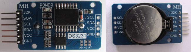
In this Medicine Reminder Project, RTC DS3231 is interfaced through the I2C protocol with Arduino Uno. You can also use the RTC IC DS1307 for reading the time with Arduino. RTC DS3231 also has built-in 32k memory, which can be used to store additional data. The RTC module is powered through the 3.3V pin of Arduino Uno. A 16x2 LCD display is interfaced using SPI. A buzzer is used to alert and remind that it’s time to take medicine. Four push buttons are used, where each has a distinct select feature. The first push button is used to remind you to take medicine once per day. The second push button is used to remind twice per day, and the third push button is used to remind thrice per day. The fourth push button is used to stop the buzzer when the user has heard the alert.
Working of the Automatic Medicine Reminder System
The Pill Reminder Alarm is powered using a 5V supply. When it first boots up, it shows a welcome message as “Welcome to Circuit Digest”. The LCD screen is set to cycle through three screens. The 1st screen shows the message “Stay Healthy, Get Well Soon”. The second screen is a help screen which tells to press select push button to select any one time-slot to remind (once/twice/thrice in a day). The time slot is changeable in the program and can be configured accordingly. Right now we have fixed this into three durations, i.e. 8 am, 2 pm, and 8 pm.
We have divided time slots into three modes. Mode 1 selects to take medicine once/day at 8am when the user presses 1st push button. Mode 2 selects to take medicine twice/day at 8am and 8 pm when the user presses 2nd push button. Mode 3 selects to take medicine thrice/day at 8am, 2 pm and 8 pm if the user presses 3rd push button.

We can also add a feature to snooze the buzzer for 10 minutes (not included in this project). When the user selects desired slots by pressing push buttons, the user input is recorded, and the time is taken from the RTC. When time is matched with the selected time slot, the buzzer starts buzzing. The user can stop the buzzer by pressing the STOP button. The same process continues for the next slot reminder. The complete process is shown in the Video given at the end of this article.
Programming for the Medicine Reminder project
It is very easy to write a program once you have thought of the ways to remind yourself to take the pills. Here it will show the reminder on display, buzz a buzzer and indicate it using an LED. It also has an option to select three time slots (once/twice/thrice per day), and when the time reaches, it starts alerting the patient by buzzing the buzzer. Then the whole system will look like the following:
User gets help instructions on display > User selects time slots (once/day, twice/day, thrice/day) > Print confirmation message on display > Time keeping started > Buzzer and LED start when time matches with user-selected slot > User stops by pushing a stop push button > End
We can change the program and hardware if we want to add more features. To understand in a much simpler way, we have broken down the program into small functions. The functions are easy to understand and implement. The complete program is given at the end of this project. Let’s start with the program.
Since we have used other peripherals like 16x2 LCD Display, RTC DS3231, we first have to include libraries for those. The library required is as follows:
<LiquidCrystal.h>
<RTClib.h>   (https://github.com/adafruit/RTClib)
<EEPROM.h>
<Wire.h>
The EEPROM library is used to keep track of user user-selected input if the Arduino is not turned on. And when the user powers on the Arduino, it gets the previous state of the push buttons using the EEPROM library. The Wire.h library is used since the RTC DS3231 module is communicated using I2C.
Always check if the RTC is properly wired or if it is not damaged, since the RTC will play an important role in time keeping of the whole reminder system.
  if (! rtc.begin()) {                      // check if rtc is connected
    Serial.println("Couldn't find RTC");
    while (1);
  }
if (rtc.lostPower()) {
    Serial.println("RTC lost power, lets set the time!");
  }
The time adjustment can be done in two ways: either automatically using the system compile time or by entering it manually. Once we have set the time, comment out the lines below unless you want to change the RTC time again.
rtc.adjust(DateTime(F(__DATE__), F(__TIME__)));
//rtc.adjust(DateTime(2019, 1, 10, 7, 59, 52));
This switch statement is used to read the previously saved state of the push button and resume the state for the appropriate and accurate reminder time.
val2 = EEPROM.read(addr);                         // read previosuly saved value of push button to start from where it was left previously
  switch (val2) {
    case 1:
      Serial.println("Set for 1/day");
      push1state = 1;
      push2state = 0;
      push3state = 0;
      pushVal = 01;
      break;
    case 2:
      Serial.println("Set for 2/day");
      push1state = 0;
      push2state = 1;
      push3state = 0;
      pushVal = 10;
      break;

    case 3:
      Serial.println("Set for 3/day");
      push1state = 0;
      push2state = 0;
      push3state = 1;
      pushVal = 11;
      break;
  }
This statement is used to get the millis to use for timing and control of the defined interval screen cycling.
currentMillisLCD = millis(); // start millis for LCD screen switching at defined interval of time
Start reading the digital pins connected to push buttons.
push1state = digitalRead(push1pin);
push2state = digitalRead(push2pin);
push3state = digitalRead(push3pin);
stopinState = digitalRead(stopPin);
The function below is used to read the push button state and write it to the EEPROM. Whenever the push button gets pressed, the state is written to EEPROM. Also, it prints the message on the LCD display of the selected user input choice. Similarly, the functions push2() and push3() are used.
void push1() {                   // function to set reminder once/day
  if (push1state == 1) {
    push1state = 0;
    push2state = 0;
    push3state = 0;
//    pushPressed = true;
    EEPROM.write(addr, 1);
    Serial.print("Push1 Written : "); Serial.println(EEPROM.read(addr));  // for debugging
    pushVal = 1;                                             //save the state of push button-1
    lcd.clear();
    lcd.setCursor(0, 0);
    lcd.print("Reminder set ");
    lcd.setCursor(0, 1);
    lcd.print("for Once/day !");
    delay(1200);
    lcd.clear();
  }
}
The function below is used to stop the buzzer and the LED. It is always good to give suggestions. Print a suggestion message on the display: “Take medicine with warm water”.
void stopPins() {                   //function to stop buzzing when user pushes stop push button
  if (stopinState == 1) {
//    stopinState = 0;
//    pushPressed = true;
    pushpressed = 1;
    lcd.clear();
    lcd.setCursor(0, 0);
    lcd.print("Take Medicine  ");
    lcd.setCursor(0, 1);
    lcd.print("with Warm Water");
    delay(1200);
    lcd.clear();
  }
}
The function below is independent of the time keeping, but always cycles through three screens, which help the user. As we are taking care of patients, let's print a greeting message as we know that emotional support is very helpful in healing patients in more quicker time. You can choose your own creative message. Let’s print a message as “Stay healthy, Get well soon”.
The second screen is for giving instructions to patients as “Press buttons for reminder.”. The Third screen is used to simply show the current date and time.
void changeScreen() {                 //function for Screen Cycling
  // Start switching screen every defined intervalLCD
  if (currentMillisLCD - previousMillisLCD > intervalLCD)             // save the last time you changed the display
  {
    previousMillisLCD = currentMillisLCD;
    screens++;
    if (screens > maxScreen) {
      screens = 0;  // all screens over -> start from 1st
    }
    isScreenChanged = true;
  }
  // Start displaying current screen
  if (isScreenChanged)   // only update the screen if the screen is changed.
  {
    isScreenChanged = false; // reset for next iteration
    switch (screens)
    {
      case getWellsoon:
        gwsMessege();                // get well soon message
        break;
      case HELP_SCREEN:
        helpScreen();               // instruction screen
        break;
      case TIME_SCREEN:
        timeScreen();                  // to print date and time
        break;
      default:
        //NOT SET.
        break;
    }
  }
}
This function is used to start buzzing and blinking the LED simultaneously when the selected time has reached.
void startBuzz() {                    // function to start buzzing when time reaches to defined interval
//  if (pushPressed == false) {

if (pushpressed == 0) {
    Serial.println("pushpressed is false in blink");
    unsigned long currentMillis = millis();

if (currentMillis - previousMillis >= interval) {
      previousMillis = currentMillis;         // save the last time you blinked the LED
      Serial.println("Start Buzzing");

if (ledState == LOW) {                  // if the LED is off turn it on and vice-versa:
        ledState = HIGH;
      }  else {
        ledState = LOW;
      }
      digitalWrite(ledPin, ledState);
    }
  }

else if (pushpressed == 1) {
    Serial.println("pushpressed is true");
    ledState = LOW;
    digitalWrite(ledPin, ledState);
  }
}
This function is used to compare the user-selected time slot at 8 am and starts buzzing the buzzer and blinking the LED until the user presses the stop push button. Similarly, the functions void at2pm() and void at8pm are used to start the buzzer and the LED at 2 pm and 8 pm.
void at8am() {                      // function to start buzzing at 8am
  DateTime now = rtc.now();
  if (int(now.hour()) >= buzz8amHH) {
    if (int(now.minute()) >= buzz8amMM) {
      if (int(now.second()) > buzz8amSS) {
        /////////////////////////////////////////////////////
        startBuzz();
        /////////////////////////////////////////////////////
      }
    }
  }
}
Technical Summary and GitHub Repository
The Technical Summary outlines the core concepts, and the GitHub Repository ensures accessible source code and documentation.


Future Enhancements for Smart Medicine Reminder
» Voice Recognition: Include voice commands for ageing users
» Camera Integration: Visual verification of medications
» Mobile App: Companion smartphone app
» Cloud Analytics: Track medication adherence
» Multi-patient Support: Hospital-level deployment ability
Conclusion
This comprehensive Arduino based medicine reminder project uses microcomputer technology combined with the healthcare field. The smart medicine reminders box is a good solution to the medication adherence problems as it is reliable and customizable.
Since the system has an expandable design, further work can be carried out in the future, making the system suitable for personal use or deployment within a healthcare facility. Once implemented and tested, such an automatic medicine reminder using Arduino can drastically improve medication adherence and hence patient outcomes.
Key Takeaways
∗ Precise timing with DS3231 RTC guarantees reliable alarms
∗ Friendly user interface with multichannel notification schemes
∗ Retains its settings in storage even through abrupt shutdowns
∗ One design that can be upgraded in the future for IoT and beyond
∗ Inexpensive medication management solution
Frequently Asked Questions about Automatic Medicine Reminder Using Arduino
⇥ Q1: What is the accuracy of the Arduino medicine reminder time?
The DS3231 RTC module will keep time with an accuracy of ±2 minutes in a year; thus, it is considered good for use in time scheduling of medicine reminders. The temperature compensation will ensure that the accuracy of the RTC module is maintained under varying environmental conditions.
⇥ Q2: Can I modify times for some medications?
Sure. The code allows simple editing of reminder times. You need to edit the variables; buzz8amHH, buzz2pmHH, and buzz8pmMM to your desired hours and minutes using a 24-hour format.
⇥ Q3: What happens if the Arduino loses power while it is running?
This system uses EEPROM to save the user settings for it. When restarted, it automatically loads the reminder mode that you had selected. The RTC module has a backup battery, so it continues to keep time.
⇥ Q4: How do I scale this project for multiple patients?
You can have a patient identification by using RFID tags, have multiple LCD displays, or create profiles for reminders in EEPROM. Arduino Mega is a good choice for more I/O pins.
⇥ Q5: Is this appropriate for critical medication reminders?
Although extremely reliable, this project is intended for general medication reminders. For critical medications, include redundant alert systems and compliance for professional medical device certification.
⇥ Q6: Is there an option to create wireless connectivity to push notifications to the mobile?
Yes! It is easy to add ESP8266 or ESP32 modules that would enable sending email alerts, SMS alerts, or push notifications using an IoT platform such as Blynk or ThingSpeak.
⇥ Q7: What are common troubleshooting methods for issues with LCD display?
These can be difficult problems to fix, but common solutions involve adjusting the contrast potentiometer, checking the power connections, confirming the wiring for data pins, or the grounds. Mostly, issues with LCD misbehaving are caused by the contrast or wiring.
This is how you can simply make your own Automatic Medicine Reminder using Arduino. You can also use ESP8266 with Arduino to make it an IoT project, which will be able to send an email alert to the user.
Complete Code and demonstration Video are given below.
Complete Project Code
//Medicine Reminder using Arduino Uno
// Reminds to take medicine at 8am, 2pm, 8pm
/*  The circuit:
   LCD RS pin to digital pin 12
   LCD Enable pin to digital pin 11
   LCD D4 pin to digital pin 5
   LCD D5 pin to digital pin 4
   LCD D6 pin to digital pin 3
   LCD D7 pin to digital pin 2
   LCD R/W pin to ground
   LCD VSS pin to ground
   LCD VCC pin to 5V
   10K resistor:
   ends to +5V and ground
   wiper to LCD VO pin (pin 3)*/
#include <LiquidCrystal.h>
#include <Wire.h>
#include <RTClib.h>
#include <EEPROM.h>
int pushVal = 0;
int val;
int val2;
int addr = 0;
RTC_DS3231 rtc;
const int rs = 12, en = 11, d4 = 5, d5 = 4, d6 = 3, d7 = 2;                 // lcd pins
LiquidCrystal lcd(rs, en, d4, d5, d6, d7);
#define getWellsoon 0
#define HELP_SCREEN 1
#define TIME_SCREEN 2
//bool pushPressed;                               //flag to keep track of push button state
int pushpressed = 0;
const int ledPin =  LED_BUILTIN;                        // buzzer and led pin
int ledState = LOW;
int Signal = 0;

int buzz = 13;
int push1state, push2state, push3state, stopinState = 0;     //
int push1Flag, push2Flag, Push3Flag = false;              // push button flags
int push1pin = 9;
int push2pin = 8;
int push3pin = 7;
int stopPin = A0;
int screens = 0;              // screen to show
int maxScreen = 2;            // screen count
bool isScreenChanged = true;
long previousMillis = 0;
long interval = 500;                   // buzzing interval
unsigned long currentMillis;
long previousMillisLCD = 0;    // for LCD screen update
long intervalLCD = 2000;          // Screen cycling interval
unsigned long currentMillisLCD;
//   Set Reminder Change Time
int buzz8amHH = 8;          //    HH - hours         ##Set these for reminder time in 24hr Format
int buzz8amMM = 00;          //    MM - Minute
int buzz8amSS = 00;          //    SS - Seconds
int buzz2pmHH = 14;          //    HH - hours
int buzz2pmMM = 00;          //    MM - Minute
int buzz2pmSS = 00;          //    SS - Seconds
int buzz8pmHH = 20;          //    HH - hours
int buzz8pmMM = 00;          //    MM - Minute
int buzz8pmSS = 00;          //    SS - Seconds

int nowHr, nowMin, nowSec;                     // to show current mm,hh,ss
// All messeges
void gwsMessege(){               // print get well soon messege
    lcd.clear();
    lcd.setCursor(0, 0);
    lcd.print("Stay Healthy :)");     // Give some cheers
    lcd.setCursor(0, 1);
    lcd.print("Get Well Soon :)");    // wish
}
void helpScreen() {              // function to display 1st screen in LCD
    lcd.clear();
    lcd.setCursor(0, 0);
    lcd.print("Press Buttons");
    lcd.setCursor(0, 1);
    lcd.print("for Reminder...!");

 }
void timeScreen() {              // function to display Date and time in LCD screen
  DateTime now = rtc.now();             // take rtc time and print in display
    lcd.clear();
    lcd.setCursor(0, 0);
    lcd.print("Time:");
    lcd.setCursor(6, 0);
    lcd.print(nowHr = now.hour(), DEC);
    lcd.print(":");
    lcd.print(nowMin = now.minute(), DEC);
    lcd.print(":");
    lcd.print(nowSec = now.second(), DEC);
    lcd.setCursor(0, 1);
    lcd.print("Date: ");
    lcd.print(now.day(), DEC);
    lcd.print("/");
    lcd.print(now.month(), DEC);
    lcd.print("/");
    lcd.print(now.year(), DEC);
}

void setup() {
  Serial.begin(9600);                      // start serial debugging
  if (! rtc.begin()) {                      // check if rtc is connected
    Serial.println("Couldn't find RTC");
    while (1);
  }
  if (rtc.lostPower()) {
    Serial.println("RTC lost power, lets set the time!");
  }
//    rtc.adjust(DateTime(F(__DATE__), F(__TIME__)));            // uncomment this to set the current time and then comment in next upload when u set the time
  rtc.adjust(DateTime(2019, 1, 10, 7, 59, 30));                // manual time set
  lcd.begin(16, 2);
  lcd.clear();
  lcd.setCursor(0, 0);
  lcd.print("Welcome To");                                      // print a messege at startup
  lcd.setCursor(0, 1);
  lcd.print("Circuit Digest");
  delay(1000);
  pinMode(push1pin, INPUT);                                    // define push button pins type
  pinMode(push2pin, INPUT);
  pinMode(push3pin, INPUT);
  pinMode(stopPin, INPUT);
  pinMode(ledPin, OUTPUT);
  delay(200);
  Serial.println(EEPROM.read(addr));
  val2 = EEPROM.read(addr);                         // read previosuly saved value of push button to start from where it was left previously
  switch (val2) {
    case 1:
      Serial.println("Set for 1/day");
      push1state = 1;
      push2state = 0;
      push3state = 0;
      pushVal = 1;
      break;
    case 2:
      Serial.println("Set for 2/day");
      push1state = 0;
      push2state = 1;
      push3state = 0;
      pushVal = 2;
      break;
    case 3:
      Serial.println("Set for 3/day");
      push1state = 0;
      push2state = 0;
      push3state = 1;
      pushVal = 3;
      break;
  }

}
void loop() {
  push1();                                             //call to set once/day
  push2();                                             //call to set twice/day
  push3();                                             //call to set thrice/day
    if (pushVal == 1) {                                // if push button 1 pressed then remind at 8am
    at8am();                                           //function to start uzzing at 8am
  }
  else if (pushVal == 2) {                             // if push button 2 pressed then remind at 8am and 8pm
    at8am();
    at8pm();                                           //function to start uzzing at 8mm
  }
  else if (pushVal == 3) {                             // if push button 3 pressed then remind at 8am and 8pm
    at8am();
    at2pm();                                            //function to start uzzing at 8mm
    at8pm();
  }

  currentMillisLCD = millis();                         // start millis for LCD screen switching at defined interval of time
  push1state = digitalRead(push1pin);                  // start reading all push button pins
  push2state = digitalRead(push2pin);
  push3state = digitalRead(push3pin);
  stopinState = digitalRead(stopPin);

  stopPins();                                            // call to stop buzzing
  changeScreen();                                        // screen cycle function

}
// push buttons
void push1() {                   // function to set reminder once/day
  if (push1state == 1) {
    push1state = 0;
    push2state = 0;
    push3state = 0;
//    pushPressed = true;
    EEPROM.write(addr, 1);
    Serial.print("Push1 Written : "); Serial.println(EEPROM.read(addr));  // for debugging
    pushVal = 1;                                             //save the state of push button-1
    lcd.clear();
    lcd.setCursor(0, 0);
    lcd.print("Reminder set ");
    lcd.setCursor(0, 1);
    lcd.print("for Once/day !");
    delay(1200);
    lcd.clear();
  }
}
void push2() {                      //function to set reminder twice/day
  if (push2state == 1) {
    push2state = 0;
    push1state = 0;
    push3state = 0;
//    pushPressed = true;
    EEPROM.write(addr, 2);
    Serial.print("Push2 Written : "); Serial.println(EEPROM.read(addr));
    pushVal = 2;
    lcd.clear();
    lcd.setCursor(0, 0);
    lcd.print("Reminder set ");
    lcd.setCursor(0, 1);
    lcd.print("for Twice/day !");
    delay(1200);
    lcd.clear();
  }
}
void push3() {                    //function to set reminder thrice/day
  if (push3state == 1) {
    push3state = 0;
    push1state = 0;
    push2state = 0;
//    pushPressed = true;
    EEPROM.write(addr, 3);
    Serial.print("Push3 Written : "); Serial.println(EEPROM.read(addr));
    pushVal = 3;
    lcd.clear();
    lcd.setCursor(0, 0);
    lcd.print("Reminder set ");
    lcd.setCursor(0, 1);
    lcd.print("for Thrice/day !");
    delay(1200);
    lcd.clear();
  }
}
void stopPins() {                   //function to stop buzzing when user pushes stop push button
  if (stopinState == 1) {
//    stopinState = 0;
//    pushPressed = true;
    pushpressed = 1;
    lcd.clear();
    lcd.setCursor(0, 0);
    lcd.print("Take Medicine  ");
    lcd.setCursor(0, 1);
    lcd.print("with Warm Water");
    delay(1200);
    lcd.clear();
  }
}

void startBuzz() {                    // function to start buzzing when time reaches to defined interval
//  if (pushPressed == false) {
 if (pushpressed == 0) {
    Serial.println("pushpressed is false in blink");
    unsigned long currentMillis = millis();
    if (currentMillis - previousMillis >= interval) {
      previousMillis = currentMillis;         // save the last time you blinked the LED
      Serial.println("Start Buzzing");
      if (ledState == LOW) {                  // if the LED is off turn it on and vice-versa:
        ledState = HIGH;
      }  else {
        ledState = LOW;
      }
      digitalWrite(ledPin, ledState);
    }
  }
  else if (pushpressed == 1) {
    Serial.println("pushpressed is true");
    ledState = LOW;
    digitalWrite(ledPin, ledState);
  }
}
void at8am() {                      // function to start buzzing at 8am
  DateTime now = rtc.now();
  if (int(now.hour()) >= buzz8amHH) {
    if (int(now.minute()) >= buzz8amMM) {
      if (int(now.second()) > buzz8amSS) {
        /////////////////////////////////////////////////////
        startBuzz();
        /////////////////////////////////////////////////////
      }
    }
  }
}
void at2pm() {                          // function to start buzzing at 2pm
  DateTime now = rtc.now();
  if (int(now.hour()) >= buzz2pmHH) {
    if (int(now.minute()) >= buzz2pmMM) {
      if (int(now.second()) > buzz2pmSS) {

        ///////////////////////////////////////////////////
        startBuzz();
        //////////////////////////////////////////////////
      }
    }
  }
}
void at8pm() {                           // function to start buzzing at 8pm
  DateTime now = rtc.now();
  if (int(now.hour()) >= buzz8pmHH) {
    if (int(now.minute()) >= buzz8pmMM) {
      if (int(now.second()) > buzz8pmSS) {

        /////////////////////////////////////////////////////
        startBuzz();
        /////////////////////////////////////////////////////
      }
    }
  }
}
//Screen Cycling
void changeScreen() {                 //function for Screen Cycling
  // Start switching screen every defined intervalLCD
  if (currentMillisLCD - previousMillisLCD > intervalLCD)             // save the last time you changed the display
  {
    previousMillisLCD = currentMillisLCD;
    screens++;
    if (screens > maxScreen) {
      screens = 0;  // all screens over -> start from 1st
    }
    isScreenChanged = true;
  }
  // Start displaying current screen
  if (isScreenChanged)   // only update the screen if the screen is changed.
  {
    isScreenChanged = false; // reset for next iteration
    switch (screens)
    {
      case getWellsoon:
        gwsMessege();                // get well soon message
        break;
      case HELP_SCREEN:
        helpScreen();               // instruction screen
        break;
      case TIME_SCREEN:
        timeScreen();                  // to print date and time
        break;
      default:
        //NOT SET.
        break;
    }
  }
}
Comments
LCD doesn't work, please let me know how that would be work properly? Hi! sir i am waiting for your feedback, Thanks
Regards
Saleh Ahmed Juwel
spin your potentiometer bcz same mistake i did . if your connections are right then it should work and find code at ttps://github.com/om6766/Personal-Arduino-Medicine-Reminder
https://github.com/om6766/Personal-Arduino-Medicine-Reminder
See the working code here and i made connections same and mine is working
LCD is working but according to code instruction the LCD is not showing reminder, let me what can i do?
Did anyone find the solution to lcd problem
i use LiquidCrystal I2C LCD 20x4 modul , How to wiring and coding sir?
what is the use of this circuit we will also remainder in mobile also ,what is the sopeciality of this circuit please tell me
I try it. But it not work. Do you have update code?
The code is working fine, what error you are facing?
SIR I HAVE MAILED TO YOUR GMAIL ACCOUNT PLEASE REPLY MI SIR I REQUEST TO YOU
Lcd is not working pls help me
Hi, I have the same problem as everyone else. My LCD is lighting up but it is not showing me anything. I tried rotating the potentiometer. Please help me as soon as possible. Thank you.

Not working LCD give me Back.