

In the digital world today, being able to accurately tell time is crucial for various embedded systems, IoT devices, and automation projects. The DS3231 RTC module is the most accurate and reliable real-time clock module to use in your Arduino projects. Unlike low-end timekeeping ICs found in basic timekeeping devices, the Arduino real time clock DS3231 features a temperature-compensated crystal oscillator (TCXO) that maintains its exceptional accuracy in varying environmental conditions. If you are developing data loggers, GPS systems, or automation controllers in time-dependent applications, you need to know how to use the DS3231 real time clock.
DIY Digital Clock using DS3231 RTC and Arduino - Quick Overview
Build Time: 2-4 hours | Cost: $20-35 | Difficulty: Beginner
What You'll Learn: I2C communication, RTC interfacing, LCD display programming, Time/date management
Applications: Digital clocks, Data loggers, Automation timers, IoT timekeeping
Table of Contents
- What is the DS3231 Real Time Clock Module?
- └ Key Features
- Pinout Diagram and Pin Configuration
- └ Understanding DS3231 Pinout Configuration
- DS3231 I2C Communication Protocol
- Frequently Asked Questions
- Module Schematic
- └ Analysis
- Set Up and Time Setting Code
- └ Installing Arduino DS3231 RTC Library
- Code for Time Setting
- Troubleshooting
- Digital Clock Project with DS3231 and LCD Display
- └ Required Components
- └ Circuit Diagram
- Code
- DS3231 vs DS1307
- └ Key Differences
- GitHub Repository
- Related Projects
What is the DS3231 Real Time Clock Module? - Complete Introduction
The DS3231 RTC module is a real-time clock that uses less power and has highly accurate communication via an I2C interface. Also, the DS3231 real time clock has its temperature-compensated crystal oscillator and crystal resonator. Hence, the timekeeping accuracy of this device is much superior to that given by most RTC modules, such as the DS1307. The module can accept a backup battery to keep time, so during a power outage, the clock continues its work.
Key Features of the Arduino Real Time Clock DS3231 include:
∗ Very high accuracy ±2ppm from 0° to +40°
∗ I2C interface, so it is easy to connect to Arduino
∗ Battery backup with automatic power switching
∗ Temperature compensated for crystal stability
∗ Two programmable time-of-day alarms
∗ Programmable square-wave output
∗ Automatic leap year and month-end date adjustment
DS3231 RTC Pinout Diagram and Pin Configuration
The DS3231 RTC pinout has 6 pins to get data from the module and supply power to the board. This DS3231 RTC pinout arrangement allows microcontroller interfacing, while also providing additional features such as square wave output and 32kHz oscillator access.
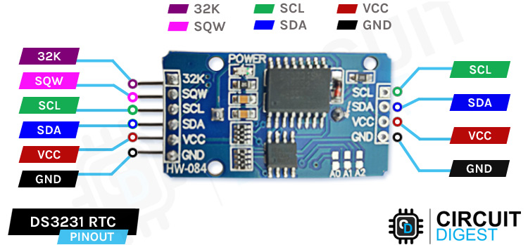
Understanding DS3231 Pinout Configuration
» 32K 32K oscillator output
»SQW Square Wave output pin
»SCL Serial Clock pin (I2C interface)
»SDA Serial Data pin (I2C interface)
»VCC is connected to the positive terminal of the power source
»GND is connected to the ground
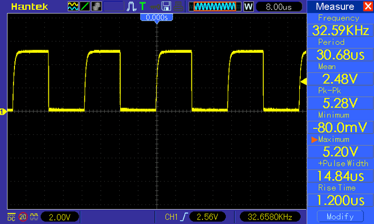
When we probe the DS3231 Module’s 32 kHz pin using an Oscilloscope, we get a 32kHz signal from the IC’s internal oscillator.
DS3231 I2C Communication Protocol
The key components of a typical DS3231 RTC Module board are the DS3231 IC and the AT24C32 EEPROM IC to store the time and date data. Other components include a Power ON LED, a few resistors, capacitors, a battery holder, and pins for connecting to the microcontroller.
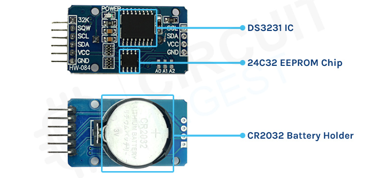
When the main power to the module is stopped, the DS3231 contains a battery input and maintains accurate time. The built-in power-sense circuit constantly checks the condition of VCC to identify power outages and switches to the backup supply automatically. So, even if the power goes out, your MCU will still be able to maintain track of time. On the DS3231 RTC Arduino, there is a CR2032 battery holder. A battery holder for a 20mm 3V lithium coin cell is located on the board's bottom side. Any CR2032 battery will work.
Charging Capability:
The module is designed in such a way that when powered externally, it can charge the battery installed on the module. But one must be careful while using a non-rechargeable CR2032 Cell, as the module will also charge the cell. The CR2032 is a 3V cell that is not rechargeable, but a rechargeable cell can be charged to 4.2V. To stop the module from charging the CR2032 non-rechargeable cell, the U4(220R) Resistor or D1 (1N4148) Diode should be desoldered.
The DS3231 RTC communicates with Arduino using the I2C communication standard, having the fixed device address of 0x68. I squared I2C interface has been standardised in such a way that there can be more than one I squared C device on the same bus; hence, it is perfect for the bigger Arduino projects, which may need several sensors and modules.
Frequently Asked Questions about DS3231 Real Time Clock
⇥ What is the difference between DS1307 and DS3231?
The most significant difference between the DS3231 and the DS1370 is the timekeeping accuracy. For timekeeping, the DS1307 has an external 32kHz crystal oscillator, while the DS3231 has an internal oscillator.
⇥ How accurate is DS3231?
The temperature-compensated crystal oscillator (TCXO) in the DS3231 and DS3234 fits the bill, with precision as good as ±2 ppm in temperatures ranging from 0°C to +40°C.
⇥ What battery does DS3231 use?
The DS3231 uses a CR2032 rechargeable cell, but if one wants to use a non-rechargeable cell, a minor modification is to be made to the module.
⇥ Why is my DS3231 RTC module not working?
The module may not be working for several reasons: Incorrect I2C wiring (check SDA/SCL w.r.t. pull-up resistors); dead backup battery; library specified differs from installed library; and possible conflicts with libraries, etc. You should check connections, correct power supply (3.3V-5V range); make sure you change the battery for one that is fresh CR2032; check that the RTClib library is installed, etc.
⇥ How durable is a DS3231 battery Backup?
Typically, a quality CR2032 battery on a DS3231 module has a shelf life of 8 - 10 years in backup mode, but this will depend on ambient temperature and, of course, quality. The low power draw of the DS3231 RTC module during the backup operation (less than 3µA) ensures a successful timekeeping duration.
DS3231 RTC Module Schematic
In this DS3231 RTC module, a number of different components are there, all of which are needed for the RTC to be kept together and store data. Knowing the DS3231 RTC module schematic is helpful when you want to troubleshoot or modify the RTC for your project.
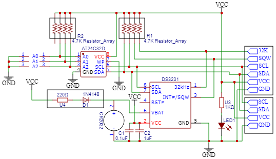
DS3231 Module Schematic Analysis
The entire DS3231 RTC module circuit diagram shows the internal configuration as follows:
∗ DS3231 IC: Main Real Time Clock controller with a TCXO integrated
∗ AT24C32 EEPROM: 32KB storage of time/date data & user applications
∗ CR2032 Battery Holder: Backup power source (3V lithium coin cell)
∗ Power Management Circuit: Automatically switches between main and backup power
∗ Pull-up Resistors: I2C bus signal conditioning (typically 4.7kΩ pulled up)
∗ Power Indicator LED: Indicates that the module has power
DS3231 RTC Arduino Programming: Setup and Time Setting Code
When programming the DS3231 RTC Arduino interface, it's important to correctly install the necessary libraries and understand the communication protocols. The DS3231 RTC module code development involves initialising the I2C connection, publishing the current time, and retrieving time data for your applications
Installing Arduino DS3231 RTC Library
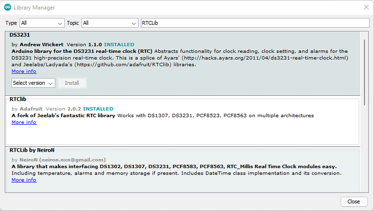
After making the above connections, you need to connect the Arduino UNO to your PC, open Arduino IDE, and install the DS3231 RTC Arduino Time Set Library. Open the Arduino IDE and select Library Manager from the menu bar. Now look for RTCLib and DS3231 and get the most recent version, as shown in the figure below.
DS3231 Arduino Code for Time Setting
The code is quite straightforward. It will set the time and then show it on the serial monitor.
rtc.adjust(DateTime(F(__DATE__),F(__TIME__)));The rtc object sets the time according to the time on your computer in this line. It will change your system's current clock time.
rtc.adjust(DateTime(2014, 1, 21, 3, 0, 0));You may manually set the time in this line by passing the date-time value to the function in the following order: year, month, date, hour, minute, and second. We'll set the time of the system in the code below. As a result, we have commented out this line.
#include <RTClib.h>
#include <Wire.h>
RTC_DS3231 rtc;
char t[32];
void setup()
{
  Serial.begin(9600);
  Wire.begin();
  rtc.begin();
  rtc.adjust(DateTime(F(__DATE__),F(__TIME__)));
  //rtc.adjust(DateTime(2019, 1, 21, 5, 0, 0));
}
void loop()
{
  DateTime now = rtc.now();
  sprintf(t, "%02d:%02d:%02d %02d/%02d/%02d", now.hour(), now.minute(), now.second(), now.day(), now.month(), now.year());
  Serial.print(F("Date/Time: "));
  Serial.println(t);
  delay(1000);
}
Arduino Real Time Clock DS3231 Issues Troubleshooting
The most common Arduino real time clock DS3231 issues when used with Arduino:
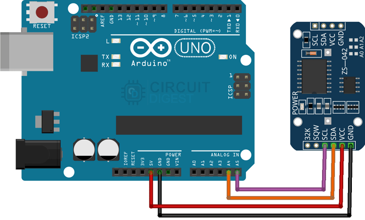
- Module not found: Check I2C connections (SDA to A4, SCL to A5)
- Incorrect time: Check the system time on the computer before uploading code to the Arduino
- Time lost: Ensure the CR2032 battery is properly installed and charged
- Bad communication: Make sure you have 4.7kΩ pull-up resistors on the I2C data lines
DIY Arduino Digital Clock Project with DS3231 and LCD Display
Constructing a digital clock with the DS3231 RTC Module and 16x2 LCD shows how to practically use the real time clock. This project shows the precision of the DS3231 real time clock combined with the use of visual display components for creating professional-quality timepieces.
Required Components for Digital Clock Project
Arduino Uno
DS3231 RTC Module
LCD Display 16*2
Jumper Wire
10K Preset
3V coin cell (CR2032)
Digital Clock Circuit Diagram with DS3231

Connect the SCL of the RTC module to the Arduino A5
Connect the SDA of the RTC module to the Arduino A4
Connect VCC to 5v and GND to GND
Connect the RS of the LCD to pin 7 of the Arduino
Connect the E of the LCD to pin 6 of the Arduino
Connect D7 of the LCD to pin 2 of the Arduino
Connect D6 of the LCD to pin 3 of the Arduino
Connect D5 of the LCD to pin 4 of the Arduino
Connect D4 of the LCD to pin 5 of the Arduino
Connect VSS,K,RW,D0,D1,D2,D3 to the GND
Connect VDD & A to the 5v
Connect VO to the potentiometer output pin ( To control the contrast of text)
Arduino Real Time Clock DS3231 LCD Code
We include the following header files in the code: Wire.h to use I2C to communicate with the module, LiquidCrystal.h to show time on the LCD display, and RTClib.h to set the time to the display and format it.
#include <Wire.h>
#include <LiquidCrystal.h>
#include <RTClib.h>
This line in the code specifies which pin of the LCD is connected to which pin of the Arduino.
LiquidCrystal lcd(7, 6, 5, 4, 3, 2); // (rs, e, d4, d5, d6, d7)If the project is fired up with a break in the connection, the code will print RTC Module not Present, in the serial monitor.
if (! rtc.begin())
  {
    Serial.println(" RTC Module not Present");
    while (1);
  }
If in case the RTC loses power and the time in the module goes wrong, the code will automatically set the time in the module, and it will take the time from the computer's clock. So, make sure that while setting the time, the clock on your PC is set at the right time.
if (rtc.lostPower())
  {
    Serial.println("RTC power failure, reset the time!");
    rtc.adjust(DateTime(F(__DATE__), F(__TIME__)));
  }
This section of the code sets the cursor on the LCD to 0 and prints the date in the format Date/Month/Year.
void displayDate()
 {
  lcd.setCursor(0,0);
  lcd.print("Date:");
  lcd.print(now.day());
  lcd.print('/');
  lcd.print(now.month());
  lcd.print('/');
  lcd.print(now.year());
 }
This section of the code sets the cursor to 1 and prints the time in the format Hour:Minute: Second.
 void displayTime()
 {
  lcd.setCursor(0,1);
  lcd.print("Time:");
  lcd.print(now.hour());
  lcd.print(':');
  lcd.print(now.minute());
  lcd.print(':');
  lcd.print(now.second());
  lcd.print("    ");
 }
After uploading the code, you will be able to see the date and time on the LCD screen.
DS3231 vs DS1307: Real Time Clock Comparison
In understanding the differences between the DS3231 RTC Module and the DS1307, you can make an informed choice for your project's timeliness requirements. The accuracy and reliability of the DS3231 real-time clock and all of the integrated features make it a very good solution.
Key Differences: DS3231 vs DS1307
Feature | DS3231 RTC Module | DS1307 |
Crystal Oscillator | Internal TCXO (Temperature Compensated) | External 32kHz Crystal Required |
Accuracy | ±2ppm (0°C to +40°C) | ±2 minutes/month (typical) |
Temperature Compensation | Automatic (-40°C to +85°C) | None |
Built-in Battery Backup | Automatic power switching | Manual configuration required |
Alarms | Two programmable alarms | None |
For the cases where the accurate capture of time is necessary using an RTC, the Arduino DS3231 real-time clock is a more stable solution than the DS1307. The DS3231 real-time clock is better suited for engineering, data logging situations, and IoT applications, where maintaining accurate time is essential.
Technical Summary and GitHub Repository
The DS3231 RTC module is a major change towards microcontrollers keeping time. Permanently integrated into the DS3231 is a temperature-compensated crystal oscillator (TCXO), making the RTC module accurate to ±2ppm within industrial temperature limits. In our GitHub repository, we have complete source code, libraries, and project files associated with all DS3231 Arduino implementations.


Creative Timekeeping and Display Projects with Arduino
Create innovative Arduino-based time display solutions by exploring a range of projects that combine real-time clocks, seven-segment displays, and LED matrices.

Multiplexing Four 7 Segment Displays using Arduino to Display Time
This tutorial is about making a Digital clock by multiplexing four- 7 segment displays using Arduino UNO and displaying the time in HH:MM format.

Arduino based Hourglass using Accelerometer and DOT Matrix Display
An Arduino hourglass project is a fun and educational project that involves creating a digital hourglass timer using an Arduino microcontroller and some simple electronic components.

Interfacing TM1637 4 Digit Seven Segment Display Module with Arduino
In this project, we will be using a ready-to-use TM1637 Based 4 Bits Red Digital Tube LED Display Module and will be testing its every feature and also in the end we will give you a working video of the model.
Complete Project Code
#include <Wire.h>
#include <LiquidCrystal.h>
#include <RTClib.h>
DateTime now;
RTC_DS3231 rtc;
LiquidCrystal lcd(7, 6, 5, 4, 3, 2); // (rs, e, d4, d5, d6, d7)
void displayDate(void);
void displayTime(void);
void setup ()
{
  Serial.begin(9600);
  lcd.begin(16,2);
  if (! rtc.begin())
  {
    Serial.println(" RTC Module not Present");
    while (1);
  }
  if (rtc.lostPower())
  {
    Serial.println("RTC power failure, reset the time!");
    rtc.adjust(DateTime(F(__DATE__), F(__TIME__)));
  }
}
void loop ()
{
  now = rtc.now();
  displayDate();
  displayTime();
}
 void displayDate()
 {
  lcd.setCursor(0,0);
  lcd.print("Date:");
  lcd.print(now.day());
  lcd.print('/');
  lcd.print(now.month());
  lcd.print('/');
  lcd.print(now.year());
 }
 void displayTime()
 {
  lcd.setCursor(0,1);
  lcd.print("Time:");
  lcd.print(now.hour());
  lcd.print(':');
  lcd.print(now.minute());
  lcd.print(':');
  lcd.print(now.second());
  lcd.print("    ");
 }

To set the Time
#include <RTClib.h>
#include <Wire.h>
RTC_DS3231 rtc;
char t[32];
void setup()
{
  Serial.begin(9600);
  Wire.begin();
  rtc.begin();
  rtc.adjust(DateTime(F(__DATE__),F(__TIME__)));
  //rtc.adjust(DateTime(2014, 1, 21, 3, 0, 0));
}
void loop()
{
  DateTime now = rtc.now();
  sprintf(t, "%02d:%02d:%02d %02d/%02d/%02d",  now.hour(), now.minute(), now.second(), now.day(), now.month(), now.year());
  Serial.print(F("Date/Time: "));
  Serial.println(t);
  delay(1000);
}

of what essence is the EEPROM. will the ds3231 still function if i reove it?