
Gesture control robotics replaces traditional buttons and joysticks with natural hand movements. This approach improves user interaction and reduces mechanical dependency on physical controllers. Sensors capture motion, convert it into digital data, and translate that data into robot movement in real time.
This project demonstrates a gesture control robot using a laptop webcam, OpenCV, and MediaPipe for real-time hand gesture control. Hand gesture control robot using OpenCV enables the system to detect and interpret movements captured by the camera to control the robot's direction, while an nRF24L01 radio module transmits commands wirelessly from a transmitter Arduino Nano to a receiver Arduino Nano mounted on the rover. The L298N motor driver on the receiver side converts those commands into motor actions.
The hand gesture control robot project source code is built around clarity, reliability, and low-cost components that makers can easily source and assemble. The complete hand gesture control robot project source code is also available on GitHub, making it easy for others to explore and build upon. This OpenCV hand gesture control robot setup forms a strong foundation for advanced human-machine interaction projects. For more exciting Gesture projects, explore our Gesture Controlled Robot Using Arduino.
This gesture control robot operates using a three-part wireless control architecture. A Python program running on the laptop captures hand gestures via the webcam, recognizes them using OpenCV hand gesture control and MediaPipe, and sends serial commands to the transmitter Arduino Nano. The transmitter forwards those commands wirelessly to the receiver Nano on the rover, which drives the motors through the L298N motor driver.
The Python application processes each camera frame in real time. MediaPipe detects 21 landmarks on the hand, and the program uses the relative positions of fingertips and knuckles to determine which fingers are raised. Each finger pattern maps to a specific movement command such as Forward, Backward, Left, Right, or Stop.
After determining the required action, Python sends a single-character command over USB serial to the transmitter Nano. The transmitter packages the data and transmits it wirelessly via the nRF24L01 module. The receiver Nano stays in constant listening mode and executes the motor routine as soon as a valid command arrives. This direct-execution model minimizes latency and makes the rover feel responsive during real-time hand gesture control.
How Does a Hand Gesture Control Robot using OpenCV Work?
A Python script on your laptop captures webcam frames → OpenCV flips and color-converts each frame → MediaPipe detects 21 hand landmarks → finger patterns map to commands (F / B / L / R / S) → PySerial sends the command to a transmitter Arduino Nano → nRF24L01 transmits wirelessly to the rover → receiver Nano drives motors via L298N. End-to-end latency is under 150 ms.
Table of Contents
- How it Works
- Hardware Components
- nRF24L01 Wireless Module Overview
- nRF24L01 Pin Connections
- Transmitter Circuit
- Receiver Circuit
- Python, OpenCV & MediaPipe Installation
- Working Principle
- Gesture Command Mapping
- Source Code - Explained
- Transmitter Arduino Code (TX Nano)
- Receiver Arduino Code (RX Nano on Rover)
- Testing and Output
- GitHub Repository
How the Real-Time Hand Gesture Control Robot Works
The real-time hand gesture control robot uses a three-stage wireless architecture: vision pipeline on the laptop, RF communication via nRF24L01, and motor execution on the rover.
| Stage | Hardware / Software | Role |
| Vision | Python + OpenCV + MediaPipe | Capture frames, detect 21 hand landmarks, classify gesture |
| Transmission | PySerial → TX Arduino Nano → nRF24L01 | Forward single-character command wirelessly to rover |
| Execution | RX Arduino Nano + L298N + DC motors | Translate command into motor action (Forward / Left / Stop …) |
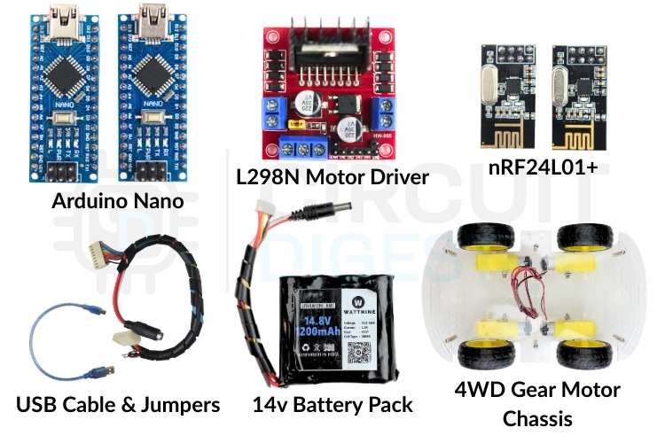
Hardware Components for the Hand Gesture Control Robot Project
These are easily available and well-supported modules to build a reliable hand gesture control robot using OpenCV project. Each component plays a clearly defined role.
- Arduino Nano (2 units)
- nRF24L01 Wireless Module (2 units)
- L298N Motor Driver
- 4-Wheel DC Gear Motor Chassis
- Laptop with Webcam
- External 12V Battery Pack
- Jumper Wires and Breadboard
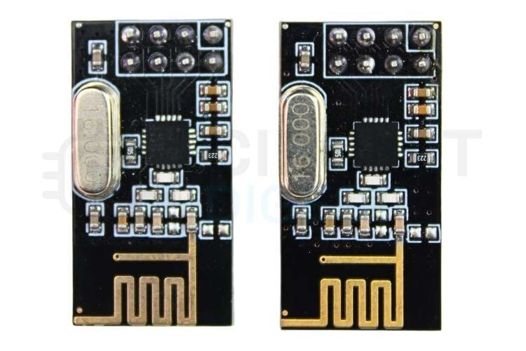
nRF24L01 Wireless Module Overview
The nRF24L01 is a low-power wireless transceiver designed for short-range communication. It operates in the 2.4 GHz ISM band and supports fast, reliable data transfer between microcontrollers. The module uses SPI communication, which allows the Arduino Nano to send and receive data with precise timing and control. Its small size and low cost make it a popular choice for wireless robotics projects.
In this project, the nRF24L01 works in a point-to-point configuration. One module stays in transmit mode on the controller side, while the other stays in receive mode on the robot side. Fixed addressing and channel selection ensure that only the intended receiver processes the incoming commands.
nRF24L01 Pin Connections (Same for Both TX and RX)
The Pin connection of the nRF24L01 module to Arduino Nano is given in the table below.
| nRF24L01 Pin | Arduino Nano Pin |
| GND | GND |
| VCC | 3.3V |
| CSN | D8 |
| CE | D9 |
| MOSI | D11 |
| MISO | D12 |
| SCK | D13 |
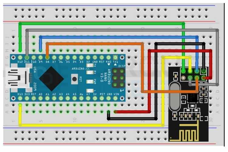
Transmitter Circuit — TX Arduino Nano Pin Connections
The transmitter unit connects to the laptop via USB. It receives single-character serial commands from the Python gesture script and forwards them wirelessly to the rover using the nRF24L01 module. The SPI interface handles all radio communication, while the USB serial port handles laptop communication.
The data flow on the transmitter side is: Laptop (Python) sends a serial character over USB to Arduino Nano TX, which reads the character and transmits it wirelessly via nRF24L01 to the rover.
Data flow on the transmitter side: Laptop (Python) → USB Serial → TX Arduino Nano → nRF24L01 → Rover.
The circuit diagram of the transmitter module is given below
Receiver Circuit — RX Arduino Nano to L298N Motor Driver Connections
The receiver unit sits on the rover and connects to the L298N motor driver. It receives wireless commands from the transmitter nRF24L01 and drives the motors accordingly. The ENB pin is connected to D10, which is a PWM-capable pin on the Nano, allowing speed control on both motor channels.
| L298N Pin | Arduino Nano Pin | Function |
| IN1 | D2 | Motor A Direction 1 |
| IN2 | D3 | Motor A Direction 2 |
| IN3 | D4 | Motor B Direction 1 |
| IN4 | D6 | Motor B Direction 2 |
| ENA | D5 (PWM) | Motor A Speed Control |
| ENB | D10 (PWM) | Motor B Speed Control |
| GND | GND | Common Ground |
| +12V | External Battery | Motor Power |
| +5V | Nano VIN | Logic Power |

Python, OpenCV & MediaPipe Installation
OpenCV (Open Source Computer Vision Library) is a powerful library for real-time image and video processing. Combined with MediaPipe from Google, it enables accurate hand landmark detection directly from a laptop webcam with no additional hardware required.
Step 1⇒ Install Python
Download Python 3.10 or 3.11 from python.org. During installation, check the option Add Python to PATH. This allows Python to be called from the command line anywhere on the system.
Step 2⇒ Create Project Folder and Virtual Environment
Open Command Prompt (not PowerShell) and run the following commands:
mkdir hand_gesture_project
cd hand_gesture_project
python -m venv venv
venv\Scripts\activate
The virtual environment keeps all project dependencies isolated. The (venv) prefix in the terminal confirms the environment is active.
Step 3⇒ Install Required Libraries
Use the command below to install the opencv-python, mediapipe, and pyserial.
pip install opencv-python mediapipe pyserialThe list of libraries and their purposes is listed in the table below
| Library | Purpose |
| opencv-python | Camera capture and image frame processing |
| mediapipe | Google hand landmark detection (21 points per hand) |
| pyserial | USB serial communication with Arduino TX Nano |
Step 4⇒ Download the MediaPipe Hand Landmarker Model
On the first run, the Python script automatically downloads the hand_landmarker.task model file (~9MB) from Google. An internet connection is required only for this one-time download. The script checks for the file before downloading to avoid repeated downloads.
How OpenCV and MediaPipe Work Together in the Gesture Control Pipeline
OpenCV captures frames from the laptop webcam as NumPy arrays in BGR format. Each frame is flipped horizontally for a natural mirror effect, then converted to RGB before being passed to MediaPipe. MediaPipe processes the frame and returns the X, Y coordinates of 21 hand landmarks. The Python code compares landmark positions to determine which fingers are raised and maps the finger pattern to a rover command.
| Landmark Index | Body Part |
| 0 | Wrist |
| 4 | Thumb Tip |
| 8 | Index Finger Tip |
| 12 | Middle Finger Tip |
| 16 | Ring Finger Tip |
| 20 | Pinky Tip |
The image below shows the landmark indexes of a hand
Gesture-to-Command Mapping for Real-Time Hand Gesture Control
The Python script detects hand gestures by analyzing the positions of 21 hand landmarks provided by MediaPipe. A finger is considered raised when its tip landmark has a lower Y coordinate than its middle knuckle landmark on screen, since Y increases downward in image coordinates. The thumb uses the X axis for comparison since it moves horizontally.
Each gesture produces a unique combination of raised fingers represented as a binary list of five values for thumb, index, middle, ring, and pinky. This list is matched against predefined gesture patterns to assign a rover command. The complete logic is part of the hand gesture control robot project source code available for reference.
| Gesture | Fingers Up | Command | Rover Action |
| Point (index only) | [0,1,0,0,0] | F | Move Forward |
| Peace / V sign | [0,1,1,0,0] | B | Move Backward |
| Gun (thumb + index) | [1,1,0,0,0] | L | Turn Left |
| Three fingers | [1,1,1,0,0] | R | Turn Right |
| Open hand | [1,1,1,1,1] | S | Stop |
| Fist | [0,0,0,0,0] | S | Stop |
Commands are throttled to send at most once every 150 milliseconds to prevent flooding the serial port. If no hand is detected in the frame, a Stop command is sent automatically to keep the rover safe.
Wireless Communication Using nRF24L01 Between Transmitter and Rover
The nRF24L01 handles all wireless communication between the transmitter Nano and the rover. Both modules are configured with the same pipe address, channel, data rate, and power level to ensure they communicate only with each other.
Python sends a single character, such as F, B, L, R, or S, over USB serial to the transmitter Nano. The Nano reads the character, packages it into a two-byte payload, and transmits it via the nRF24L01. The receiver Nano on the rover stays in continuous listening mode and triggers the appropriate motor function immediately upon receiving a valid command.
Using RF24_PA_LOW power level improves stability at short range and reduces power consumption. A fixed channel at 108 avoids interference from common WiFi bands. The compact single-character payload keeps transmission time minimal and response latency low.
Hand Gesture Control Robot Project Source Code - Explained
Python Gesture Detection Script (gesture.py)
This script runs on the laptop. It captures webcam frames, detects hand landmarks using MediaPipe, classifies the gesture, and sends the command character over serial to the TX Nano. This forms the core of the hand gesture control robot using an OpenCV pipeline. The very first thing this script does is try to open a serial connection to the Arduino board using the COM port and baud rate defined at the top. The two-second sleep is important because Arduinos reboot the moment a serial connection is made, and sending data before it finishes will result in nothing going through. If the connection fails, it just sets Arduino to None and keeps running, so you can still test the vision side without any hardware connected.
Serial connection with Arduino reset handling
 try:
  arduino = serial.Serial(SERIAL_PORT, BAUD_RATE, timeout=1)
   time.sleep(2)
except Exception as e:
   arduino = None
The hand detection model does all the heavy lifting in understanding what your hand looks like on camera. Instead of making the user manually locate and download the file, the script checks whether it already exists; if it does not, it automatically downloads it from Google's servers. This keeps the setup process clean and means anyone can just run the script without reading extra instructions.
Automatic model download
if not os.path.exists(MODEL_PATH):
urllib. request.urlretrieve('https://storage.googleapis.com/mediapipe-models/
   hand_landmarker/hand_landmarker/float16/1/hand_landmarker.task', MODEL_PATH)
This function figures out which fingers are raised and which are folded by comparing each fingertip position against the joint two steps below it. If the tip is higher on screen than that joint, the finger is considered up and gets, otherwise, it gets a 0. The thumb is handled separately since it bends sideways, so it compares horizontal position instead of vertical.
Finger-state detection
fingers.append(1 if landmarks[4].x < landmarks[3].x else 0)
for tip in TIP_IDS[1:]:
   fingers.append(1 if landmarks[tip].y < landmarks[tip-2].y else 0)
Once the finger state list is ready, this function matches it against predefined patterns to decide what the rover should do. Each pattern maps to a direction command, a short letter code to send over serial, and a color for the screen overlay. Any combination that does not match a known gesture defaults to stop, which is a smart safety choice,e so the rover never keeps moving when the hand signal is unclear.
Gesture-to-command mapping
if f == [0,1,0,0,0]: return ('FORWARD', 'F', (0,255,0))
if f == [0,1,1,0,0]: return ('BACKWARD', 'B', (0,0,255))
if f == [1,1,1,1,1]: return ('STOP', 'S', (0,255,255))
The main loop runs continuously until you press Q to quit. Every frame gets flipped like a mirror and converted to RGB before being passed to the detector, and the result drives both the screen label and the serial command. The time check ensures the Arduino is not flooded with hundreds of identical messages per second, which could cause it to behave unpredictably.
Transmitter Arduino Code (TX Nano)
This program is used to send wireless commands using the nRF24L01 RF module. It reads a single character from the Serial Monitor and transmits it to another nRF24 module. The main purpose of this code is to act as a transmitter (TX) that sends control commands like Forward, Backward, Left, Right, and Stop.
#include <SPI.h>
#include <RF24.h>
RF24 radio(9, 8);  // CE=D9, CSN=D8
const byte address[6] = "00001";
First, the required libraries are included. SPI.h is needed because the nRF24L01 communicates using the SPI protocol. RF24.h is the library that makes it easy to control the nRF24 module. The line RF24 radio(9, 8) creates a radio object and defines the CE and CSN pins connected to Arduino pins 9 and 8. The address variable defines the communication pipe address. Both transmitter and receiver must use the same address to communicate properly.
void setup() {
 Serial.begin(9600);
 if (!radio.begin()) {
   Serial.println("nRF24 not responding! Check wiring.");
   while (1) {}
 }
 radio.openWritingPipe(address);
 radio.setPALevel(RF24_PA_LOW);
 radio.stopListening();
 Serial.println("TX Ready");
}
Inside the setup() function, serial communication is started at a 9600 baud rate so that commands can be sent from the Serial Monitor. The radio.begin() function initializes the nRF24 module. If the module does not respond, the program prints an error message and stops using an infinite loop. The openWritingPipe(address) function sets the address for transmission. The setPALevel(RF24_PA_LOW) sets the power level of the module to low, which is suitable for short-distance communication and reduces power consumption. The stopListening() function sets the module to transmitter mode. Finally, “TX Ready” is printed to indicate that the transmitter is ready.
void loop() {
 if (Serial.available() > 0) {
In the loop() function, the program continuously checks if any data is available from the Serial Monitor. Serial.available() returns the number of bytes received. If it is greater than zero, it means a character has been typed and sent.
  char cmd = Serial.read();
   if (cmd=='F'||cmd=='B'||cmd=='L'||cmd=='R'||cmd=='S') {
     char payload[2];
     payload[0] = cmd;
     payload[1] = '\0';
     radio.write(&payload, sizeof(payload));
     Serial.print("Sent: ");
     Serial.println(cmd);
   }
Here, the program reads one character from the Serial Monitor and stores it in the variable cmd. It checks whether the character is one of the allowed commands: ‘F’, ‘B’, ‘L’, ‘R’, or ‘S’. If it matches, a small character array called payload is created. The command character is stored in the first position, and a null character ('\0') is added to properly terminate the string. The radio.write() function sends this payload wirelessly to the receiver. After sending, the program prints the sent command on the Serial Monitor for confirmation.
Receiver Arduino Code (RX Nano on Rover)
This sketch runs on the Arduino Nano mounted on the rover. It listens for wireless commands and drives the motors at 50% speed through the L298N motor driver. ENB is connected to D10, a PWM-capable pin, for proper speed control on both channels. This program acts as a wireless receiver that controls two DC motors using commands received from an nRF24L01 module. It is mainly used in simple robot car projects where movement is controlled remotely. The receiver continuously listens for single-character commands such as ‘F’ (Forward), ‘B’ (Backward), ‘L’ (Left), ‘R’ (Right), and ‘S’ (Stop). When a valid command is received, it processes that character and drives the motors in the required direction. The overall structure is simple: receive data wirelessly, identify the command, and control the motors accordingly.
RF24 radio(9, 8);
const byte address[6] = "00001";
These two lines create the radio communication object and define the wireless address. The RF24 radio(9, 8); line initializes the nRF24L01 module by specifying that the CE pin is connected to digital pin 9 and the CSN pin is connected to digital pin 8 of the Arduino. These pins are responsible for controlling communication between the Arduino and the RF module through SPI. The address defined in the next line acts like a communication channel name. Both the transmitter and receiver must use the same address; otherwise, they will not be able to communicate with each other.
#define IN1 2
#define IN2 3
These lines define two digital pins that are connected to the motor driver inputs. They control the rotation direction of the first motor. By setting these pins HIGH or LOW in different combinations, the motor can rotate forward or backwards. These pins do not control speed; they only control direction. Using #define makes the code easier to read and modify because you can change the PIN in one place instead of searching through the entire program.
#define IN1 2
#define IN2 3
These lines define the direction control pins for the second motor. Just like IN1 and IN2, these pins determine whether the second motor rotates forward or backwards. In a two-wheel robot car, one motor controls the left wheel, and the other controls the right wheel. By changing the direction of each motor independently, the robot can move forward, backward, or turn left and right.
#define ENA 5
#define ENB 10
These two pins are connected to the enable pins of the motor driver. Unlike the IN pins, ENA and ENB are used for speed control. Since these pins support PWM (Pulse Width Modulation), the analogWrite() function can be used to vary the voltage supplied to the motors. This allows smooth control over motor speed instead of running the motors only at full speed.
int motorSpeed = 128;This variable stores the speed value that will be applied to both motors. PWM values range from 0 to 255, where 0 means completely off and 255 means full speed. A value of 128 represents approximately 50% duty cycle, which gives moderate motor speed. This makes the robot move at a stable and controlled pace instead of running too fast.
radio.begin();
radio.startListening();
These lines initialise the nRF24 module and set it to receiving mode. The radio.begin() function starts communication with the module and prepares it for operation. The radio.startListening() function switches the module into receiver mode so it can continuously wait for incoming data from the transmitter. Without this function, the module would not receive any commands.
if (radio.available())
 radio.read(&payload, sizeof(payload));
These lines check whether any wireless data has been received. The radio.available() function returns true if new data is waiting in the buffer. If data is available, it is read into the payload array using radio.read(). This payload contains the command character sent by the transmitter. After reading, the program extracts the first character and uses it to decide how the motors should move.
if (cmd=='F') moveForward();
else if (cmd=='S') stopMotors();
These lines demonstrate how the received command controls the robot’s movement. If the character received is ‘F’, the moveForward() function is called, which sets the motor direction pins and applies speed through PWM. If the command is ‘S’, the stopMotors() function is executed, which disables motor movement by setting the speed to zero and turning off all direction pins. Similar conditions exist for backward and turning movements. This simple decision-making structure allows the robot to respond immediately to wireless control commands. If you're interested in more Arduino-based projects, do check out our Arduino Projects Collection.
Testing the Hand Gesture Control Robot - Step-by-Step Sequence
Testing focused on verifying gesture detection accuracy, serial communication reliability, wireless stability, and motor response. Follow this sequence for a reliable first test:
- Upload the TX code to the Nano connected to the laptop. Open Serial Monitor (9600 baud) and type F - confirm it prints Sent: F.
- Connect the RX Nano to the laptop separately. Open its Serial Monitor and check it prints Received: F when TX sends.
- Close ALL Serial Monitors before running Python.
- Mount the RX Nano on the rover and connect to L298N. Power rover with a 12V battery.
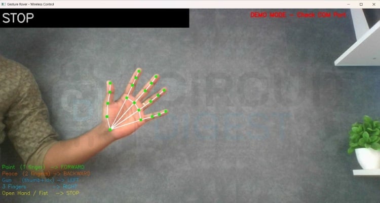
- Run python gesture.py on the laptop. Show hand gestures to the camera and observe the rover movement.
The rover responds immediately to gesture changes, with smooth transitions between movement directions. The on-screen HUD displays the active gesture name, finger count, and serial connection status in real time.
Applications of the Hand Gesture Control Robot
Hand gesture control robots enable intuitive control without physical interfaces. The same control logic used in this project can scale easily to more complex robotic systems.
- Remote control robotic vehicles and surveillance rovers
- Assistive robots for basic mobility tasks
- Educational platforms for learning computer vision and embedded systems
- Human-machine interface experimentation
- Contactless control systems for hazardous environments
- Prototype control models for industrial robotics and automation
Future Enhancements for the Gesture Control Robot Using OpenCV
This project provides a solid baseline, but several improvements can increase performance, reliability, and usability.
- Add two-hand gesture support for simultaneous speed and direction control
- Implement variable motor speed based on finger count or hand distance from the camera
- Add obstacle detection using ultrasonic or IR sensors on the rover
- Replace character commands with structured data packets for higher efficiency
- Use external antenna nRF24L01 modules to improve wireless range
- Add a real-time video stream from a camera mounted on the rover
- Train a custom gesture classifier using scikit-learn for more gesture variety
Frequently Asked Questions
⇥ Why does the nRF24L01 require 3.3V power?
The nRF24L01 uses internal RF circuitry that operates strictly at 3.3V; supplying 5V damages the internal transceiver permanently. Even brief exposure to higher voltage causes unstable transmission or complete module failure. A regulated 3.3V supply with proper grounding ensures stable wireless performance.
⇥ Why is the Serial Monitor closed before running Python?
Python and Arduino IDE Serial Monitor cannot share the same COM port simultaneously. Whichever opens first locks the port, blocking the other. Always close the Serial Monitor before running the Python script, or it will fail to connect with a Permission Denied error.
⇥ Why is motor speed limited to 50%?
The L298N and DC gear motors can draw more than 5A at full speed under load, which risks overheating the motor driver and draining the battery rapidly. Setting motorSpeed to 128 out of 255 limits PWM duty cycle to 50%, keeping current draw within safe limits while still providing sufficient torque for movement.
⇥ What is the maximum operating range of the system?
Using RF24_PA_LOW, the reliable range is typically 10 to 30 meters indoors, depending on obstacles and interference. Switching to RF24_PA_HIGH with a decoupling capacitor across the nRF24 VCC and GND pins can extend the range further. Open areas allow better performance than enclosed rooms.
⇥ Can this work without a virtual environment?
Yes, but a virtual environment is strongly recommended. It prevents library version conflicts between projects. If using PowerShell, activate with venv\Scripts\Activate.ps1 after enabling script execution, or switch to Command Prompt and use venv\Scripts\activate instead.
⇥ What if the rover moves in the wrong direction?
Swap the IN1 and IN2 definitions in the RX Arduino code for the affected motor side. Alternatively, physically swap the two motor wires going into the L298N output terminals for that channel. No hardware damage occurs from reversed motor polarity.
Conclusion
This hand gesture control robot OpenCV project presents a complete and practical embedded system that combines computer vision, serial communication, and wireless motor control into a single working design. The Python script accurately captures hand movement using a standard laptop webcam, classifies gestures using OpenCV and MediaPipe landmark analysis, and sends commands reliably over USB serial. The transmitter Arduino Nano forwards those commands wirelessly to the rover via the nRF24L01 module, and the receiver Nano translates them into smooth motor actions through the L298N driver at a safe 50% speed.
The design avoids unnecessary complexity by using simple gesture logic, stable communication settings, and direct pin control, making the system easy to understand, debug, and extend. This project serves as a strong learning platform for computer vision, wireless robotics, and human-machine interaction, while also providing a solid base for future upgrades such as variable speed control, multi-gesture support, and autonomous obstacle avoidance. Curious about real-time gesture control projects? Take a look at our Arduino based Gesture controlled Robot using an accelerometer.
Hand Gesture Control Robot OpenCV GitHub Repository
If you want the project files, wiring diagrams, or sample videos, they are stored cleanly in this GitHub repository.


Similar Projects Using OpenCV
These projects demonstrate how OpenCV can be used to build practical computer vision applications like emotion detection, motion monitoring, and face recognition. Each project explains the setup, coding, and working process, helping you understand how to implement real-time image processing and AI-based vision systems on Raspberry Pi.

Real Time Face Recognition with Raspberry Pi and OpenCV Primary tabs View
In this tutorial, we will learn how we can build our own Face Recognition system using the OpenCV Library on Raspberry Pi.

CCTV Motion Detection with Alarm using OpenCV on Raspberry Pi
Build a Raspberry Pi CCTV system using OpenCV to detect motion in real time and trigger an instant alarm for smart, low-cost surveillance.

Raspberry Pi Based Emotion Recognition using OpenCV, TensorFlow, and Keras
An AI-powered Raspberry Pi project that uses OpenCV with TensorFlow and Keras to recognize and classify human emotions from facial expressions in real time.
Complete Project Code
import cv2, mediapipe as mp, os, urllib.request, serial, time
from mediapipe. tasks import python
from mediapipe. tasks.python import vision

SERIAL_PORT  = 'COM4'   # Change to your TX Nano COM port
BAUD_RATE    = 9600
CMD_INTERVAL = 0.15
try:
    arduino = serial.Serial(SERIAL_PORT, BAUD_RATE, timeout=1)
    time.sleep(2)
    print(f'Connected to TX Nano on {SERIAL_PORT}')
except Exception as e:
    print(f'Serial failed: {e}  -- Running DEMO MODE')
    arduino = None

def send_command(cmd):
    if arduino and arduino.is_open:
       arduino.write((cmd + '\n').encode())
MODEL_PATH = 'hand_landmarker.task'
if not os.path.exists(MODEL_PATH):
    print('Downloading model (~9MB)...')
   urllib. request.urlretrieve(
       'https://storage.googleapis.com/mediapipe-models/'
       'hand_landmarker/hand_landmarker/float16/1/hand_landmarker.task',
       MODEL_PATH)
    print('Download complete!')
TIP_IDS = [4, 8, 12, 16, 20]
def fingers_up(landmarks):
    fingers = []
    fingers.append(1 if landmarks[4].x < landmarks[3].x else 0)
    for tip in TIP_IDS[1:]:
       fingers.append(1 if landmarks[tip].y < landmarks[tip-2].y else 0)
    return fingers
def classify_gesture(f):
    if f == [0,1,0,0,0]: return ('FORWARD',  'F', (0,255,0))
    if f == [0,1,1,0,0]: return ('BACKWARD', 'B', (0,0,255))
    if f == [1,1,0,0,0]: return ('LEFT',     'L', (255,165,0))
    if f == [1,1,1,0,0]: return ('RIGHT',    'R', (255,200,0))
    if f == [1,1,1,1,1]: return ('STOP',     'S', (0,255,255))
    if f == [0,0,0,0,0]: return ('STOP',     'S', (0,255,255))
    return                       ('STOP',     'S', (200,200,200))

options = vision.HandLandmarkerOptions(
   base_options=python.BaseOptions(model_asset_path=MODEL_PATH),
    num_hands=1,
   min_hand_detection_confidence=0.5,
   min_hand_presence_confidence=0.5,
   min_tracking_confidence=0.5)
detector = vision.HandLandmarker.create_from_options(options)
cap = cv2.VideoCapture(0)
cap.set(cv2.CAP_PROP_FRAME_WIDTH, 1280)
cap.set(cv2.CAP_PROP_FRAME_HEIGHT, 720)
last_cmd, last_cmd_time = '', 0
while True:
    ret, frame = cap.read()
    if not ret: break
    frame = cv2.flip(frame, 1)
    h, w, _ = frame.shape
    rgb = cv2.cvtColor(frame, cv2.COLOR_BGR2RGB)
    mp_image = mp.Image(image_format=mp.ImageFormat.SRGB, data=rgb)
    result = detector.detect(mp_image)
    label, cmd, color = 'No Hand - STOP', 'S', (200,200,200)
    if result.hand_landmarks:
       for lms in result.hand_landmarks:
           f = fingers_up(lms)
           label, cmd, color = classify_gesture(f)
    now = time.time()
    if cmd != last_cmd or (now - last_cmd_time) > CMD_INTERVAL:
       send_command(cmd)
       last_cmd, last_cmd_time = cmd, now
    cv2.rectangle(frame, (0,0), (700,70), (0,0,0), -1)
    cv2.putText(frame, label, (10,50),
               cv2.FONT_HERSHEY_SIMPLEX, 1.5, color, 3)
    cv2.imshow('Gesture Rover', frame)
    if cv2.waitKey(1) & 0xFF == ord('q'):
       send_command('S')
       break
cap.release()
cv2.destroyAllWindows()
if arduino: arduino.close()
