

GSM modules are fascinating to use especially when our project requires remote access. These modules could make all actions that our normal mobile phone could do, like making/receiving a call, sending/receiving a SMS, connecting to internet using GPRS etc. You can also connect a normal microphone and speaker to this module and converse on your mobile calls. This will open doors to lot of creative projects if it could be interfaced with a Microcontroller. Hence in this tutorial we will learn how we can Interface the GSM module (SIM900A) with our PIC microcontroller and will demonstrate it by making and receiving call using GSM Module. We have previously interfaced it with Arduino and Raspberry Pi for calling and messaging:
Materials Required:
- PIC Microcontroller (PIC16F877A)
- GSM module (SIM900 or any other)
- Connecting wires
- 12V Adapter
- PicKit 3
GSM Module:

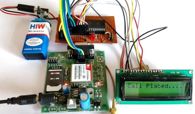
The GSM module can be used even without any microcontroller by using the AT command mode. As shown above the GSM module comes with a USART adapter which can be directly interfaced to the computer by using a MAX232 module or the Tx and Rx pins can be used to connect it to a Microcontroller. You can also notice the other pins like MIC+, MIC-, SP+, SP- etc where a microphone or a Speaker can be connected. The module can be powered by a 12V adapter through a normal DC barrel jack.
Insert your SIM card in the slot of the module and power it on, you should notice a power LED going ON. Now wait for a minute or so, and you should see a red (or any other colour) LED Flashing once for every 3 seconds. This means that your Module was capable to establish connection with your SIM card. Now you can proceed with connecting you module with Phone or any Microcontroller.
Communicating with GSM module using AT commands:
As you might have guessed it, the GSM module can communicate through Serial communication and could understand only one language and that is “AT commands”. Whatever that you might want to tell or ask to the GSM module it should only be via AT commands. For example if you want to know if your module is active. You should ask (send) a command like “AT” and your module will reply “OK”.
These AT commands are well explained in its data sheet and can be found here in its official datasheet. Okay! Okay! It is a 271 page datasheet and you might take days to read through them. So I have given some most important AT commands below for you to get this up and running soon.
AT | Replies with OK for Acknowledgement |
AT+CPIN? | Check signal Quality |
AT+COPS? | Find service provider name |
ATD96XXXXXXXX; | Call to the specific number, ends with semi-colon |
AT+CNUM | Find the number of SIM card (might not work for some SIM) |
ATA | Answer the Incoming Call |
ATH | Hang off the current Incoming call |
AT+COLP | Show incoming call number |
AT+VTS=(number) | Send DTMF number. You can use any number on your mobile keypad for (number) |
AT+CMGR | AT+CMGR=1 reads message at first position |
AT+CMGD=1 | Delete message at first position |
AT+CMGDA=”DEL ALL” | Delete All messages from SIM |
AT+CMGL=”ALL” | Read all messaged from SIM |
AT+CMGF=1 | Set SMS configuration. “1” is for text only mode |
AT+CMGS = “+91 968837XXXX” >CircuitDigest Text<Ctrl+z> | Sends SMS to a particular number here 968837XXXX. When you see “>” start entering the text. Press Ctrl+Z to send the text. |
AT+CGATT? | To check for internet connection on SIM card |
AT+CIPSHUT | To close TCP connection, meaning to disconnect form internet |
AT+CSTT = “APN”,”username”,”Pass” | Connect to GPRS with your APN and Pass key. Can be obtained from Network Provider. |
AT+CIICR | Check if SIM card has data pack |
AT+CIFSR | Get IP of the SIM network |
AT+CIPSTART = “TCP”,”SERVER IP”,”PORT” | Used to set a TCP IP connection |
AT+CIPSEND | This command is used to send data to server |
Circuit Diagram:
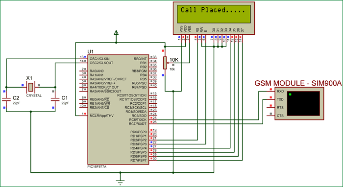
The connection diagram for Interfacing GSM module with PIC microcontroller is shown below.

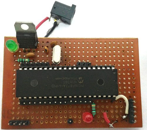
We have simply interfaced the Tx and Rx pins of the GSM module with the Rx and Tx pins of the PIC MCU PIC16F877A respectively. This will establish a Serial connection between both. Also, so do not forget to common ground both the GSM and PIC module. We have also used a LCD display to know the status of our GSM module. Once the connections are done your hardware will look like something below.
The PIC Perf board was made for our PIC tutorial series, in which we learnt how to use PIC microcontroller. You might want to go back to those PIC Microcontroller tutorials using MPLABX and XC8 if you do not know how to burn a program using Pickit 3, since I will be skipping all those basic information.
Programming you PIC Microcontroller:
The complete program for this project can be found at the bottom of this tutorial. Here I will explain some important functions and pieces of code. This program also has a LCD codes which were from Interfacing LCD with PIC Microcontroller, you can visit that tutorial if you are curious to know how LCD can be used with PIC microcontroller.
As said earlier, we are going to communicate between PIC and GSM using AT commands through the Serial mode of communication. So, first we have to initialize the USART communication module in our PIC microcontroller by using the Initialize_SIM900(); function. Inside this function we declare the Tx and RX pins and initialize Asynchronous reception and transmission at 9600 baud rate and 8-bit mode.
//***Initialize UART for SIM900**//
void Initialize_SIM900(void)
{
    //****Setting I/O pins for UART****//
    TRISC6 = 0; // TX Pin set as output
    TRISC7 = 1; // RX Pin set as input
    //________I/O pins set __________//

    /**Initialize SPBRG register for required
    baud rate and set BRGH for fast baud_rate**/
    SPBRG = 129; //SIM900 operates at 9600 Baud rate so 129
    BRGH  = 1;  // for high baud_rate
    //_________End of baud_rate setting_________//

    //****Enable Asynchronous serial port*******//
    SYNC  = 0;    // Asynchronous
    SPEN  = 1;    // Enable serial port pins
    //_____Asynchronous serial port enabled_______//
    //**Lets prepare for transmission & reception**//
    TXEN  = 1;    // enable transmission
    CREN  = 1;    // enable reception
    //__UART module up and ready for transmission and reception__//
    //**Select 8-bit mode**//
    TX9   = 0;    // 8-bit reception selected
    RX9   = 0;    // 8-bit reception mode selected
    //__8-bit mode selected__//
}
//________UART module Initialized__________//
Now we need to read and write information from/to our GSM module. For this we use the functions _SIM900_putch(), _SIM900_getch(), _SIM900_send_string(), _SIM900_print(). These functions use the Transmit and receive buffer register such as TXREG and RCREG to read or write data serially.
//**Function to send one byte of date to UART**//
void _SIM900_putch(char bt)
{
    while(!TXIF);  // hold the program till TX buffer is free
    TXREG = bt; //Load the transmitter buffer with the received value
}
//_____________End of function________________//
//**Function to get one byte of date from UART**//
char _SIM900_getch()
{
    if(OERR) // check for Error
    {
        CREN = 0; //If error -> Reset
        CREN = 1; //If error -> Reset
    }
   while(!RCIF);  // hold the program till RX buffer is free
    return RCREG; //receive the value and send it to main function
}
//_____________End of function________________//
//**Function to convert string to byte**//
void SIM900_send_string(char* st_pt)
{
    while(*st_pt) //if there is a char
        _SIM900_putch(*st_pt++); //process it as a byte data
}
//___________End of function______________//
//**End of modified Codes**//
void _SIM900_print(unsigned const char *ptr) {
    while (*ptr != 0) {
        _SIM900_putch(*ptr++);
    }
The above functions are universal and need not be changed for any applications. They were explained only to give a rough intro. You can dive deep into them if you want through understanding.
Now inside our main function, we initialize the USART connection and check if we are able to receive a “OK” when we send “AT” by using the below line of code
do
    {
    Lcd_Set_Cursor(2,1);
    Lcd_Print_String("Module not found");
    }while (!SIM900_isStarted()); //wait till the GSM to send back "OK"
    Lcd_Set_Cursor(2,1);
    Lcd_Print_String("Module Detected ");
    __delay_ms(1500);
The function SIM900_isStarted(); will send “AT” to the GSM and waits for response “OK” from it. If yes, it will return 1 else 0;
If the module is not detected or if there is any connection problem then the LCD will show “Module not found”, else it will show Module is detected and proceed to next step where, we check if the SIM card can be detected by the below line of code.
/*Check if the SIM card is detected*/
    do
    {
    Lcd_Set_Cursor(2,1);
    Lcd_Print_String("SIM not found   ");
    }while (!SIM900_isReady()); //wait till the GSM to send back "+CPIN: READY"
    Lcd_Set_Cursor(2,1);
    Lcd_Print_String("SIM Detected    ");
    __delay_ms(1500);
The function SIM900_isReady() will send “AT+CPIN?” to the GSM and waits for response “+CPIN: READY” from it. If yes, it will return 1 else 0;
If a SIM card if found we will get SIM detected displayed on the LCD. Then, we can try placing a call by using the command “ATDmobilenumber;”. Here as an example I have used my number as ATD93643159XX;. You have to replace your respective mobile number there.
   /*Place a Phone Call*/
     do
    {
    _SIM900_print("ATD93643XXXXX;\r\n");  //Here we are placing a call to number 93643XXXXX
    Lcd_Set_Cursor(1,1);
    Lcd_Print_String("Placing Call....");
    }while (_SIM900_waitResponse() != SIM900_OK); //wait till the ESP send back "OK"
    Lcd_Set_Cursor(1,1);
    Lcd_Print_String("Call Placed....");
    __delay_ms(1500);
Once the call is placed the LCD will display Call Placed and you should receive an incoming call to that specified number.
You can also call to the mobile number connected to the GSM module and get notified about it on your LCD screen y using the below code
    while(1)
    {
        if (_SIM900_waitResponse() == SIM900_RING) //Check if there is an incoming call
        {
          Lcd_Set_Cursor(2,1);
          Lcd_Print_String("Incoming Call!!.");
        }
    }
When the GSM module detects a incoming call it will display Incoming call on the second line of the LCD module. The function _SIM900_waitResponse() will check for incoming data from the GSM module. When it receives SIM900_RING, which is equivalent to “RING” due to the waitResponce(), we will display the status “Incoming call”.
You can create your own functions like this to perform almost all types of activates using GSM module. If you want to have things hardcoded, you can simply use the __SIM900_print() function to send any AT command like this below.
_SIM900_print("AT+CPIN?\r\n");Remember that all you command should be followed with “\r\n” to indicate that the command is terminating.
Simulation:
Once you have understood how the program works you can try simulating and make changes to fit your needs. Simulation will save you a lot of time. The simulation is done using Proteus and it looks like below.
As you can see we have used virtual terminal option in Proteus to check if the Program is responding as expected. We can feed in the values through the pop-up dialog box. For example as soon as we hit run, a black dialog box like above will appear and display AT, this means that it has send the GSM module AT, now we can reply to PIC by typing in the box as “OK” and hit enter and the PIC will respond to it. Similarly we can try for all AT commands.
Making and Receiving calls using GSM and PIC:
Once you understand how the code and hardware works, simply upload the below program to PIC and power on the module. Your LCD should display “Module Detected”, “SIM detected” and “call Placed” if everything is working fine. Once you see “Call placed” you will get a incoming call to the number specified in the program.
You can also try calling to the number present in the GSM module and your LCD will display “Incoming call” to indicate the SIM is being called.
The complete working of the project is shown in the video below. Hope you understood the project and enjoyed doing it. If you have any problem in getting things work, post your question on the comment section or on our Forums and I will be happy to help you out.
Complete Project Code
// CONFIG
#pragma config FOSC = HS       // Oscillator Selection bits (HS oscillator)
#pragma config WDTE = OFF       // Watchdog Timer Enable bit (WDT disabled)
#pragma config PWRTE = OFF       // Power-up Timer Enable bit (PWRT enabled)
#pragma config BOREN = OFF        // Brown-out Reset Enable bit (BOR enabled)
#pragma config LVP = OFF        // Low-Voltage (Single-Supply) In-Circuit Serial Programming Enable bit (RB3 is digital I/O, HV on MCLR must be used for programming)
#pragma config CPD = OFF        // Data EEPROM Memory Code Protection bit (Data EEPROM code protection off)
#pragma config WRT = OFF        // Flash Program Memory Write Enable bits (Write protection off; all program memory may be written to by EECON control)
#pragma config CP = OFF         // Flash Program Memory Code Protection bit (Code protection off)
//End of CONFIG registers

#define _XTAL_FREQ 20000000
#define RS RD2
#define EN RD3
#define D4 RD4
#define D5 RD5
#define D6 RD6
#define D7 RD7

#define SIM900_OK 1
#define SIM900_READY 2
#define SIM900_FAIL 3
#define SIM900_RING 4
#define SIM900_NC 5
#define SIM900_UNLINK 6

#include<xc.h>

// Wait for any response on the input
inline unsigned char _SIM900_waitResponse(void);
    int recv;
    char p =1;


//LCD Functions Developed by Circuit Digest.
void Lcd_SetBit(char data_bit) //Based on the Hex value Set the Bits of the Data Lines
{
if(data_bit& 1)
D4 = 1;
else
D4 = 0;

if(data_bit& 2)
D5 = 1;
else
D5 = 0;

if(data_bit& 4)
D6 = 1;
else
D6 = 0;

if(data_bit& 8)
D7 = 1;
else
D7 = 0;
}

void Lcd_Cmd(char a)
{
RS = 0;
Lcd_SetBit(a); //Incoming Hex value
EN  = 1;
        __delay_ms(4);
        EN  = 0;
}

void Lcd_Clear()
{
Lcd_Cmd(0); //Clear the LCD
Lcd_Cmd(1); //Move the curser to first position
}

void Lcd_Set_Cursor(char a, char b)
{
char temp,z,y;
if(a== 1)
{
 temp = 0x80 + b - 1; //80H is used to move the curser
z = temp>>4; //Lower 8-bits
y = temp & 0x0F; //Upper 8-bits
Lcd_Cmd(z); //Set Row
Lcd_Cmd(y); //Set Column
}
else if(a== 2)
{
temp = 0xC0 + b - 1;
z = temp>>4; //Lower 8-bits
y = temp & 0x0F; //Upper 8-bits
Lcd_Cmd(z); //Set Row
Lcd_Cmd(y); //Set Column
}
}

void Lcd_Start()
{
  Lcd_SetBit(0x00);
  for(int i=1065244; i<=0; i--)  NOP();
  Lcd_Cmd(0x03);
__delay_ms(5);
  Lcd_Cmd(0x03);
__delay_ms(11);
  Lcd_Cmd(0x03);
  Lcd_Cmd(0x02); //02H is used for Return home -> Clears the RAM and initializes the LCD
  Lcd_Cmd(0x02); //02H is used for Return home -> Clears the RAM and initializes the LCD
  Lcd_Cmd(0x08); //Select Row 1
  Lcd_Cmd(0x00); //Clear Row 1 Display
  Lcd_Cmd(0x0C); //Select Row 2
  Lcd_Cmd(0x00); //Clear Row 2 Display
  Lcd_Cmd(0x06);
}

void Lcd_Print_Char(char data)  //Send 8-bits through 4-bit mode
{
   char Lower_Nibble,Upper_Nibble;
   Lower_Nibble = data&0x0F;
   Upper_Nibble = data&0xF0;
   RS = 1;             // => RS = 1
   Lcd_SetBit(Upper_Nibble>>4);             //Send upper half by shifting by 4
   EN = 1;
   for(int i=2130483; i<=0; i--)  NOP();
   EN = 0;
   Lcd_SetBit(Lower_Nibble); //Send Lower half
   EN = 1;
   for(int i=2130483; i<=0; i--)  NOP();
   EN = 0;
}

void Lcd_Print_String(char *a)
{
int i;
for(i=0;a[i]!='\0';i++)
  Lcd_Print_Char(a[i]);  //Split the string using pointers and call the Char function
}
/*****End of LCD Functions*****/


//***Initialize UART for SIM900**//
void Initialize_SIM900(void)
{
    //****Setting I/O pins for UART****//
    TRISC6 = 0; // TX Pin set as output
    TRISC7 = 1; // RX Pin set as input
    //________I/O pins set __________//

    /**Initialize SPBRG register for required
    baud rate and set BRGH for fast baud_rate**/
    SPBRG = 129; //SIM900 operates at 9600 Baud rate so 129
    BRGH  = 1;  // for high baud_rate
    //_________End of baud_rate setting_________//

    //****Enable Asynchronous serial port*******//
    SYNC  = 0;    // Asynchronous
    SPEN  = 1;    // Enable serial port pins
    //_____Asynchronous serial port enabled_______//
    //**Lets prepare for transmission & reception**//
    TXEN  = 1;    // enable transmission
    CREN  = 1;    // enable reception
    //__UART module up and ready for transmission and reception__//

    //**Select 8-bit mode**//
    TX9   = 0;    // 8-bit reception selected
    RX9   = 0;    // 8-bit reception mode selected
    //__8-bit mode selected__//
}
//________UART module Initialized__________//


//**Function to send one byte of date to UART**//
void _SIM900_putch(char bt)
{
    while(!TXIF);  // hold the program till TX buffer is free
    TXREG = bt; //Load the transmitter buffer with the received value
}
//_____________End of function________________//


//**Function to get one byte of date from UART**//
char _SIM900_getch()
{
    if(OERR) // check for Error
    {
        CREN = 0; //If error -> Reset
        CREN = 1; //If error -> Reset
    }

    while(!RCIF);  // hold the program till RX buffer is free

    return RCREG; //receive the value and send it to main function
}
//_____________End of function________________//


//**Function to convert string to byte**//
void SIM900_send_string(char* st_pt)
{
    while(*st_pt) //if there is a char
        _SIM900_putch(*st_pt++); //process it as a byte data
}
//___________End of function______________//
//**End of modified Codes**//

void _SIM900_print(unsigned const char *ptr) {
    while (*ptr != 0) {
        _SIM900_putch(*ptr++);
    }
}

bit SIM900_isStarted(void) {
    _SIM900_print("AT\r\n");
    return (_SIM900_waitResponse() == SIM900_OK);
}

bit SIM900_isReady(void) {
    _SIM900_print("AT+CPIN?\r\n");
    return (_SIM900_waitResponse() == SIM900_READY);
}

inline unsigned char _SIM900_waitResponse(void) {
    unsigned char so_far[6] = {0,0,0,0,0,0};
    unsigned const char lengths[6] = {2,12,5,4,6,6};
    unsigned const char* strings[6] = {"OK", "+CPIN: READY", "ERROR", "RING", "NO CARRIER", "Unlink"};
    unsigned const char responses[6] = {SIM900_OK, SIM900_READY, SIM900_FAIL, SIM900_RING, SIM900_NC, SIM900_UNLINK};
    unsigned char received;
    unsigned char response;
    char continue_loop = 1;
    while (continue_loop) {
        received = _SIM900_getch();
        for (unsigned char i = 0; i < 6; i++) {
            if (strings[i][so_far[i]] == received) {
                so_far[i]++;
                if (so_far[i] == lengths[i]) {
                    response = responses[i];
                    continue_loop = 0;
                }
            } else {
                so_far[i] = 0;
            }
        }
    }
    return response;
}

void main(void)
{
    //I/O Declarations//
    TRISD = 0x00;  //LCD pins on port D as output
    //End of I/O declaration//

    Lcd_Start();   //Initialize LCD
    Initialize_SIM900();//lets get our Serial ready for action


    Lcd_Set_Cursor(1,1);
    Lcd_Print_String("SIM900 & PIC");

       /*Check if the SIM900 communication is successful*/
    do
    {
    Lcd_Set_Cursor(2,1);
    Lcd_Print_String("Module not found");
    }while (!SIM900_isStarted()); //wait till the GSM to send back "OK"
    Lcd_Set_Cursor(2,1);
    Lcd_Print_String("Module Detected ");
    __delay_ms(1500);


       /*Check if the SIM card is detected*/
     do
    {
    Lcd_Set_Cursor(2,1);
    Lcd_Print_String("SIM not found   ");
    }while (!SIM900_isReady()); //wait till the GSM to send back "+CPIN: READY"
    Lcd_Set_Cursor(2,1);
    Lcd_Print_String("SIM Detected    ");
    __delay_ms(1500);

   Lcd_Clear();


     /*Place a Phone Call*/
     do
    {
    _SIM900_print("ATD93643XXXXX;\r\n");  //Here we are placing a call to number 93643XXXXX
    Lcd_Set_Cursor(1,1);
    Lcd_Print_String("Placing Call....");
    }while (_SIM900_waitResponse() != SIM900_OK); //wait till the ESP send back "OK"
    Lcd_Set_Cursor(1,1);
    Lcd_Print_String("Call Placed....");
    __delay_ms(1500);

    while(1)
    {
        if (_SIM900_waitResponse() == SIM900_RING) //Check if there is an incoming call
        {
          Lcd_Set_Cursor(2,1);
          Lcd_Print_String("Incoming Call!!.");
        }
    }
}
Comments
i am getting 100 errors and 8 warnings for the given program while compiling.please help me.i am not able to figure out the problem.i have included all libraries also.
Help can be provided only if you show your error messages, paste them here or make a separate thread on the forum.
Realy interesting sir , I which to join an MQ2 ' gas sensor ' to this projet ... please for the code that will permit an impulse from 'MQ2' to the 'GSM ' passing via PIC 16F877A .
thanks
Sir,
I want one problem for pic .logic is 1 send msg for target number .using GSM module
May you please assist me. I want to get sms alerts whenever power fails and whenever a motor trips. I want to use sim900a module and pic f877a . I don't know how best to interface the the two. I simulated using proteus and everything seems to be ok..How do i interface the two practically
Just follow this tutorial it also explains how to interface both practically. If you have any problem in interfacing it write it here in comment section
I am doing this project outside Asia. Will Sim900a work outside India?
Which country are you planning to use. Sim900A is supported by almost all countries since it can work with frequencies 850/ 900/ 1800/ 1900 MHz frequency
C:\Users\priti\Desktop\New folder (2)\gsm5.c:124:Warning [2058] call of function without prototype
C:\Users\priti\Desktop\New folder (2)\gsm5.c:150:Warning [2058] call of function without prototype
C:\Users\priti\Desktop\New folder (2)\gsm5.c:154:Warning [2058] call of function without prototype
C:\Users\priti\Desktop\New folder (2)\gsm5.c:182:Error [1105] symbol 'SYNC' has not been defined
C:\Users\priti\Desktop\New folder (2)\gsm5.c:182:Error [1101] lvalue required
C:\Users\priti\Desktop\New folder (2)\gsm5.c:183:Error [1105] symbol 'SPEN' has not been defined
C:\Users\priti\Desktop\New folder (2)\gsm5.c:183:Error [1101] lvalue required
C:\Users\priti\Desktop\New folder (2)\gsm5.c:186:Error [1105] symbol 'TXEN' has not been defined
C:\Users\priti\Desktop\New folder (2)\gsm5.c:186:Error [1101] lvalue required
C:\Users\priti\Desktop\New folder (2)\gsm5.c:187:Error [1105] symbol 'CREN' has not been defined
C:\Users\priti\Desktop\New folder (2)\gsm5.c:187:Error [1101] lvalue required
C:\Users\priti\Desktop\New folder (2)\gsm5.c:191:Error [1105] symbol 'TX9' has not been defined
C:\Users\priti\Desktop\New folder (2)\gsm5.c:191:Error [1101] lvalue required
C:\Users\priti\Desktop\New folder (2)\gsm5.c:192:Error [1105] symbol 'RX9' has not been defined
C:\Users\priti\Desktop\New folder (2)\gsm5.c:192:Error [1101] lvalue required
C:\Users\priti\Desktop\New folder (2)\gsm5.c:201:Error [1105] symbol 'TXIF' has not been defined
C:\Users\priti\Desktop\New folder (2)\gsm5.c:210:Error [1105] symbol 'OERR' has not been defined
C:\Users\priti\Desktop\New folder (2)\gsm5.c:212:Error [1105] symbol 'CREN' has not been defined
C:\Users\priti\Desktop\New folder (2)\gsm5.c:212:Error [1101] lvalue required
C:\Users\priti\Desktop\New folder (2)\gsm5.c:213:Error [1105] symbol 'CREN' has not been defined
C:\Users\priti\Desktop\New folder (2)\gsm5.c:213:Error [1101] lvalue required
C:\Users\priti\Desktop\New folder (2)\gsm5.c:216:Error [1105] symbol 'RCIF' has not been defined
C:\Users\priti\Desktop\New folder (2)\gsm5.c:239:Warning [2054] suspicious pointer conversion
C:\Users\priti\Desktop\New folder (2)\gsm5.c:244:Warning [2054] suspicious pointer conversion
C:\Users\priti\Desktop\New folder (2)\gsm5.c:258:Warning [2058] call of function without prototype
C:\Users\priti\Desktop\New folder (2)\gsm5.c:280:Warning [2058] call of function without prototype
C:\Users\priti\Desktop\New folder (2)\gsm5.c:285:Warning [2066] type qualifier mismatch in assignment
C:\Users\priti\Desktop\New folder (2)\gsm5.c:291:Warning [2066] type qualifier mismatch in assignment
C:\Users\priti\Desktop\New folder (2)\gsm5.c:294:Warning [2066] type qualifier mismatch in assignment
C:\Users\priti\Desktop\New folder (2)\gsm5.c:295:Warning [2058] call of function without prototype
C:\Users\priti\Desktop\New folder (2)\gsm5.c:302:Warning [2066] type qualifier mismatch in assignment
C:\Users\priti\Desktop\New folder (2)\gsm5.c:305:Warning [2066] type qualifier mismatch in assignment
C:\Users\priti\Desktop\New folder (2)\gsm5.c:306:Warning [2058] call of function without prototype
C:\Users\priti\Desktop\New folder (2)\gsm5.c:308:Warning [2058] call of function without prototype
C:\Users\priti\Desktop\New folder (2)\gsm5.c:314:Warning [2054] suspicious pointer conversion
C:\Users\priti\Desktop\New folder (2)\gsm5.c:316:Warning [2066] type qualifier mismatch in assignment
C:\Users\priti\Desktop\New folder (2)\gsm5.c:319:Warning [2066] type qualifier mismatch in assignment
C:\Users\priti\Desktop\New folder (2)\gsm5.c:320:Warning [2058] call of function without prototype
C:\Users\priti\Desktop\New folder (2)\gsm5.c:327:Warning [2066] type qualifier mismatch in assignment
inline unsigned char _SIM900_waitResponse(void) {
unsigned char so_far[6] = {0,0,0,0,0,0};
unsigned const char lengths[6] = {2,12,5,4,6,6};
unsigned const char* strings[6] = {"OK", "+CPIN: READY", "ERROR", "RING", "NO CARRIER", "Unlink"};
unsigned const char responses[6] = {SIM900_OK, SIM900_READY, SIM900_FAIL, SIM900_RING, SIM900_NC, SIM900_UNLINK};
unsigned char received;
unsigned char response;
char continue_loop = 1;
while (continue_loop) {
received = _SIM900_getch();
for (unsigned char i = 0; i < 6; i++) {
if (strings[i][so_far[i]] == received) {
so_far[i]++;
if (so_far[i] == lengths[i]) {
response = responses[i];
continue_loop = 0;
}
} else {
so_far[i] = 0;
}
}
}
return respon
please explain this function
i got error msg in this tow ligne
CREN = 0; //If error -> Reset
CREN = 1; //If error -> Reset
What will be the SPBRG value for 8MHz crystal? do i have to brgh = 1? I have displayed reception on lcd.. but it shows blank. But proteus simulation runs ok!
HI we are trying to read SMS from sim900a modem using pic microcontroller which is not working for me
.How ever i can send an SMS using PIC to any number its working . having trouble in reading SMS . can you pls help
Hey please i am trying to do what you did, so don't know if you found a solution to your problem
Warning [374] D:\GSM.c; 33.8 missing basic type; int assumed
Error [314] D:\GSM.c; 33.8 ";" expected
Warning [374] D:\GSM.c; 229.8 missing basic type; int assumed
Error [314] D:\GSM.c; 229.8 ";" expected
Warning [359] D:\GSM.c; 266.32 illegal conversion between pointer types
pointer to const unsigned char -> pointer to unsigned char
Warning [359] D:\GSM.c; 272.36 illegal conversion between pointer types
pointer to const unsigned char -> pointer to unsigned char
Warning [359] D:\GSM.c; 276.36 illegal conversion between pointer types
pointer to const unsigned char -> pointer to unsigned char
Warning [359] D:\GSM.c; 284.36 illegal conversion between pointer types
pointer to const unsigned char -> pointer to unsigned char
Warning [359] D:\GSM.c; 287.36 illegal conversion between pointer types
pointer to const unsigned char -> pointer to unsigned char
Warning [359] D:\GSM.c; 298.36 illegal conversion between pointer types
pointer to const unsigned char -> pointer to unsigned char
Warning [359] D:\GSM.c; 301.35 illegal conversion between pointer types
pointer to const unsigned char -> pointer to unsigned char
Warning [359] D:\GSM.c; 309.36 illegal conversion between pointer types
pointer to const unsigned char -> pointer to unsigned char
********** Build failed! **********
I don't want to use the GSM module....can a phone aux output be used instead,and will the code still work
What change if i use sim800l v5 module
And what's power should l supply
"inline unsigned char " any Buddy explain me which type of "return type" it is?
In this gsm code, if i add ADC function then ADC not work continuously, only work first ONE time.
can u help me.
sounds like a fun project, will try it, nice
I WANT READ ADC FUNCTION, SO HOW CAN GET UART INTERRUPT IN THIS CODE, PLEASE HELP
I´m running your code and check it out in Proteus, i don´t have any problem with compilation but, at the time I run in Proteus it doesn´t work, i show you an image, i hope you can help me soon.
WELL I TRIED AGAIN THIS code and everything was simulated in Proteus succesfully :)
Now, my question is, how should i work on this project for sending a message instead a call? Please help me!!!!!
Just change the AT commands in the code accordingly
Please need help on that, i tried this but it doesn't compile and am not sure it will send a message to the number
_SIM900_print("ATE0\r\n");
__delay_ms(1000);
_SIM900_print("AT\r\n");
__delay_ms(1000);
_SIM900_print("AT+CMGF = 1\r\n");
__delay_ms(1000);
_SIM900_print("AT+CNMI = 1,2,0,0,0\r\n");
__delay_ms(1000);
_SIM900_print("AT+CMGS =" +xxxxxxxxxx"\r\n");
__delay_ms(10000);
_SIM900_print("Give me that A GRADE \r\n");
Lcd_Set_Cursor(1,1);
Lcd_Print_String("Message sent....");
}while (1); //wait till the ESP send back "OK"
Could you please tell me which program tht you use to compie the code?
I need your help!!
sir,can you please explain these two
unsigned char so_far[6] = {0,0,0,0,0,0};
if (strings[i][so_far[i]] == received)
Greetings sir, my lcd displays "SIM900 & PIC not found"...and i actually tried calling the number in the module and i get a ringing tone...so don't know what could be wrong.
Solved my previous problem, since i had a different module wasn't connecting to UART ports but now everything is detected but my phone doesn't seem to ring...help please. do i have to include country code like "+225xxxxxx" ?
This project was tested. But i have 2 errors. how to fix
Here:
make[2]: *** [build/default/production/Gsm/newmain.p1] Error 1
make[1]: *** [.build-conf] Error 2
make: *** [.build-impl] Error 2
BUILD FAILED (exit value 2, total time: 4s)
Hello, can i get please the gsm library on proteus for pic18f, just couldnt find it
bit SIM900_isStarted(void)
I got an error in mplab regarding above fn.What kind of return typr is "bit"?.Plz help!
2 errors while building the GSM code in MPLAB X
12 warnings and 2 errors generated.
(908) exit status = 1
nbproject/Makefile-default.mk:107: recipe for target 'build/default/production/sim900Call.p1' failed
make[2]: Leaving directory 'D:/PICprojects/ALL_PIC_projects/MYpicPROJECTS/SIM900Lcall.X'
nbproject/Makefile-default.mk:91: recipe for target '.build-conf' failed
make[1]: Leaving directory 'D:/PICprojects/ALL_PIC_projects/MYpicPROJECTS/SIM900Lcall.X'
nbproject/Makefile-impl.mk:39: recipe for target '.build-impl' failed
make[2]: *** [build/default/production/sim900Call.p1] Error 1
make[1]: *** [.build-conf] Error 2
make: *** [.build-impl] Error 2
BUILD FAILED (exit value 2, total time: 1s)
PLEASE HELP ME OUT AND EXPLAIN THE STEPS TO SOLVE THE ABOVE 2 ERRORS IN MPLAB X
inline unsigned char _SIM900_waitResponse(void)
Please explain this function

Interesting