 Vedhathiri
Author

Ever wondered if a small, low-cost board like the ESP32-CAM can actually recognise objects or even identify Indian currency notes? In this project, the answer is a clear yes. We combine the ESP32-CAM with the powerful Edge Impulse platform to build a system capable of object detection and image classification right at the edge. By using the Edge Impulse at every step from collecting image data and labelling different currency denominations, to training the machine-learning model, and finally deploying it directly onto the ESP32-CAM. Once deployed, the ESP32-CAM processes images in real time and predicts the denomination of the currency note placed in front of it. To make the output easy to understand, LEDs are used as visual indicators. Each denomination has its own LED, and when a note is detected, the corresponding LED glows. At the same time, the detected denomination is displayed on the Serial Monitor, giving both visual and textual confirmation. Previously, we built a similar Object Detection using ESP32-CAM and Edge Impulse project focused on vegetable detection, and this project extends the concept to currency recognition. Kindly explore other ESP32-CAM projects to further enhance your understanding and curiosity about embedded AI and edge computing. This comprehensive guide demonstrates how to build an ESP32-CAM currency recognition system using Edge Impulse and Arduino programming
Indian Currency Note Recognition using ESP32-CAM & Edge Impulse - Quick Overview
Build Time: 8-14 hours | Cost: $15-28 | Difficulty: Intermediate
What You'll Learn: TinyML / Edge AI, ESP32-CAM camera interfacing, Edge Impulse workflow, Image classification & object detection on microcontroller, Arduino library deployment
Applications: Assistive device for the visually impaired, Fake note detection (future scope), Automated retail/POS currency validation, Vending machine note acceptor, Currency counting system
Table of Contents
- What is ESP32-CAM Currency Recognition?
- Components Required
- Circuit Diagram
- Hardware Setup
- └ Hardware Connection Guide
- Complete Workflow
- └ Dataset Collection Methods
- Edge Impulse Model Training
- └ Impulse Design Configuration
- └ Model Training and Evaluation
- Arduino Programming
- Testing
- └ Real-World Performance Results
- Troubleshooting
- GitHub Repository
What is ESP32-CAM Currency Recognition?
ESP32-CAM currency recognition utilising Machine Learning to Identify & Classify Indian Rupee Notes in Real-Time embraces the power of the ESP32-CAM as well as Machine Learning (ML) technology and uses an embedded AI Project to perform highly advanced image classification activities using inexpensive microcontrollers that do not require any internet connection or cloud services to operate.
The Edge Impulse Platform (one of the best TinyML Development Platforms) allows for training of a custom object recognition model to specifically recognise Indian Rupee notes. Once deployed, the ESP32 currency recognition programming processes images locally, providing instant visual feedback through LED indicators while displaying results on the Serial Monitor.
Understanding AI on Edge and Object Recognition Technology
What exactly is AI on Edge? In simple terms, AI on Edge, also known as edge computing, means running artificial intelligence algorithms directly on embedded devices such as microcontrollers and microprocessors, instead of sending data to cloud servers for processing. This local processing brings several advantages: lower latency, reduced communication costs, improved data privacy, and faster real-time responses. You might wonder, wasn’t cloud computing supposed to handle all AI tasks? That was true earlier, mainly because cloud platforms were easier to deploy and had powerful resources. However, with today’s advancements in embedded hardware, even compact devices are capable of handling AI workloads efficiently at the device level. One of its most important applications is object recognition, a computer vision technique that allows machines to identify and classify objects in images or video streams. This gives devices the ability to see and interpret visual information much like humans do. You may often hear terms like object detection and image recognition; they are closely related and commonly used interchangeably in this context. You can also explore our other AI projects to implement more ideas of your own.
For ESP32 currency recognition, this technology analyses visual features like patterns, colours, text, and security elements unique to each denomination, achieving accurate classification through trained neural networks.
Components Required for ESP32 Currency Recognition System
Below are the components which are essential to build the currency recognition system.
| S.NO | Components | Quantity | Purpose |
| 1 | ESP32 Cam | 1 | Acts as a main microcontroller and camera module. It captures images of Indian currency notes and runs the Edge Impulse |
| 2 | USB to Serial Converter | 1 | Used to load the program to the controller |
| 3 | LED | Red, Green, Yellow, Blue-Each 1 | Provides the visual indication of the detected currency denomination |
| 4 | 100 Ohms | 4 | Limit the current flowing through the LEDs to prevent damage |
| 5 | Breadboard | 1 | Used for connecting everything without soldering and easy testing |
| 6 | Jumper Wires | Required Quantity | Used to interconnect between ESP32-CAM, LEDs, Resistors, and Breadboard |
| 7 | Arduino IDE | - | Used to compile and deploy the Code to the module |
| 8 | Edge Impulse Studio | - | Used to collect, train and label the datasets |
Circuit Diagram of Currency Recognition System:
The circuit diagram illustrates the interfacing of the ESP32-CAM module with a USB-to-Serial converter. Since the ESP32-CAM does not have a built-in USB interface, the USB-to-Serial converter provides the necessary TX, RX, 5V, and GND connections to upload the program and monitor data.

Additionally, four LEDs are connected to the GPIO pins of the ESP32-CAM, with each LED representing a different currency denomination. When an ESP32 currency recognition systemspecific denomination is detected or recognized by the ESP32-CAM, the corresponding LED glows to indicate successful identification. Each LED is connected through a resistor (100 Ω) to protect it from excessive current and ensure safe operation.
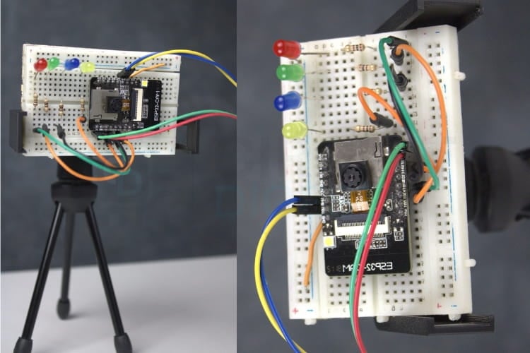
Hardware Setup of Currency Recognition System
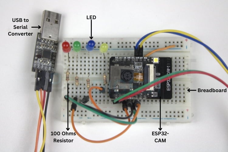
This image shows an ESP32-CAM build setup on a breadboard, where the ESP32-CAM module is connected to a USB-to-Serial converter for programming and communication. Multiple LEDs with current-limiting resistors (100 Ω) are used as status indicators, all interconnected using jumper wires on the breadboard for easy prototyping and testing.
Hardware Connection Guide
Connect components following these steps for proper ESP32-CAM currency recognition operation:
∗ Connect the FTDI TX to the ESP32-CAM RX pin
∗ Connect the FTDI RX to the ESP32-CAM TX pin
∗ Connect FTDI 5V to ESP32-CAM 5V pin
∗ Connect FTDI GND to ESP32-CAM GND pin
∗ For programming mode: Connect GPIO0 to GND
∗ Connect LED anodes to GPIO pins through 100Ω resistors
∗ Connect all LED cathodes to the common GND
Complete ESP32 Currency Recognition Programming Workflow
The overall procedure can be divided into three stages: data acquisition, machine learning model development using Edge Impulse, and prototype testing. For data acquisition, images can be collected using any preferred method. Ensure that at least 50 images per object are captured, as a larger dataset generally improves classification accuracy. While images can include different backgrounds, a plain background is recommended for better results. Additionally, selecting an optimal image resolution helps reduce training time. The 256×256 pixels provide a good balance between accuracy and efficiency. Each phase requires careful attention to ensure accurate ESP32-CAM currency recognition performance.
Dataset Collection Methods for Currency Recognition
The first and easiest method of data acquisition is to download an existing dataset from the internet. High-quality training data forms the foundation of accurate ESP32 currency recognition. Popular platforms such as Kaggle, Google Dataset Search, and OpenML provide a wide range of publicly available datasets. Since this project focuses on Indian currency recognition, we require images of different Indian currency notes such as ₹10, ₹20, ₹50 and ₹500.
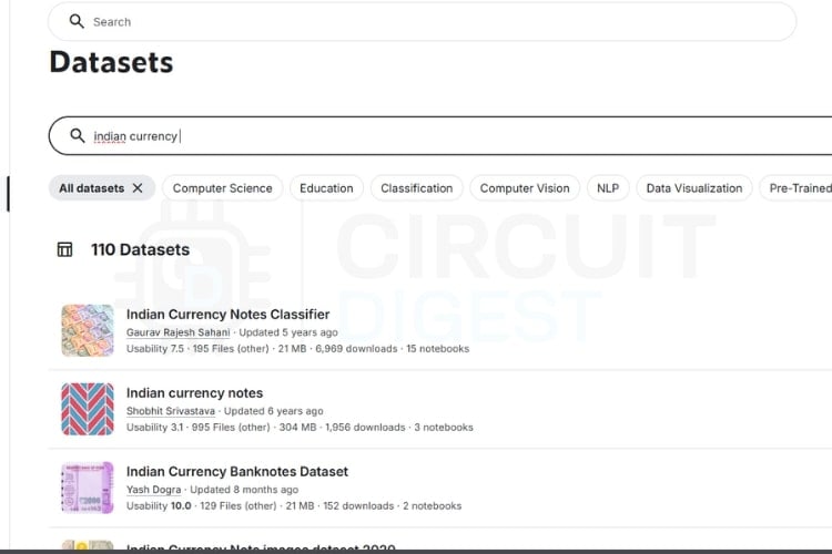
As discussed earlier, you can search for suitable datasets on these platforms and select one that meets your requirements while following the data collection checklist. The image above shows sample search results obtained from Kaggle. Choosing the right dataset may take some time; however, in this project, data will not be collected using this method due to certain limitations. We are going to collect our own image.
Edge Impulse Model Training for ESP32 Currency Recognition
Edge Impulse streamlines the entire machine learning workflow for embedded devices. Follow these steps to train your ESP32-CAM currency recognition model:
If you are just getting started with the ESP32-CAM module, we recommend checking out our guides “How to Program the ESP32-CAM?” and Object Detection using ESP32-CAM and Edge Impulse which together explain the complete workflow in a simple and easy-to-follow manner. You can check out these two to get the full process done. Even though the guidance is already provided, the steps are also listed below for reference.
* Note: To program and make the system work, you need to wire the ESP32 cam in the right way while uploading and after uploading, so check the links to do it perfectly.
Project Setup and Data Upload
⇒ Step 1: Installing the Required Library
First, install the EloquentEsp32cam library from the Arduino Library Manager. This library simplifies image capture and data collection using the ESP32-CAM.
⇒ Step 2: Opening the Example Code and Making Required Changes
Open the example sketch located at:
Examples->EloquentEsp32cam->Collect_Images_for_EdgeImpulse
In the code, enter your Wi-Fi hotspot details by modifying the following lines at the beginning of the program:
#define WIFI_SSID "SSID"
#define WIFI_PASS "PASSWORD"
#define HOSTNAME "esp32cam"
Replace SSID and PASSWORD with your Wi-Fi credentials. Also, change the line camera.pinout wroom_s3() to camera.pinout.aithinker(). Note that the ESP32-CAM supports only 2.4 GHz Wi-Fi networks. Once the details are updated, the code is ready to be uploaded to the ESP32-CAM.
⇒ Step 3: Accessing the ESP32-CAM Web Server and Capturing Images
After a successful boot, open the Serial Monitor at a 115200 baud rate to find the IP address assigned to the ESP32-CAM. Copy this IP address and paste it into a web browser on any device connected to the same Wi-Fi network. This will open the web interface hosted by the ESP32-CAM.
Once connected, click “START COLLECTING” to begin capturing images. Additional options such as “Clear” and “Download” will appear. After collecting sufficient images, click “Download”, enter the label name, and a ZIP file containing the captured images will be downloaded.
Ensure proper lighting and a clear view of the currency note during image capture. Using a plain, single-colour background, preferably white, will improve data quality. Repeat this process for all required Indian currency denominations. After completing data collection, proceed to the Edge Impulse model training stage.
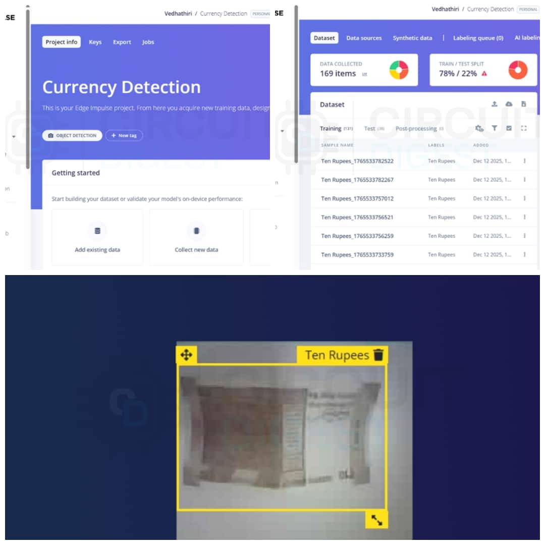
This image shows the Edge Impulse dashboard used for dataset collection, labelling, and train-test split. It also shows an example of object detection where a ₹10 note is labelled and bounded using a trained model.
Impulse Design Configuration
Create an account on the Edge Impulse website and log in. Click Create New Project, enter a project name (for example, Indian Currency Recognition), keep the default settings, and open the project dashboard. Navigate to Data Acquisition and upload the collected images into the training and testing datasets. Open the Labelling Queue and draw bounding boxes around each currency note, keeping the boxes as square as possible (96×96 px).

Use Track objects between frames and Label Suggestions (YOLOv5) to reduce manual labelling effort. Go to Create Impulse, set the image size to 96×96, select Image as the processing block, and Object Detection as the learning block, then save the impulse. In the Image processing block, enable Grayscale and generate features. Verify feature separation in the feature explorer to ensure good model accuracy.
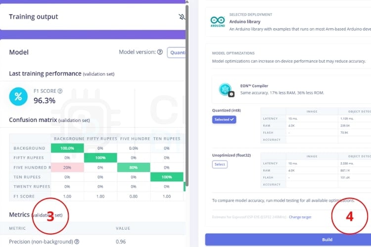
Model Training and Evaluation
Open the Object Detection tab, configure training cycles and learning rate, and start model training. Evaluate model performance using the F1 score after training completes. Then, navigate to Deployment, choose Arduino Library as the deployment option, select Espressif ESP-EYE (ESP32 240 MHz) as the target, and build the library. Download and install the generated Arduino library to deploy the model on the ESP32-CAM.
ESP32 Currency Recognition Arduino Programming
Deploy the trained model to your ESP32-CAM hardware following these programming steps:
Extract the ZIP file downloaded from Edge Impulse after the build process (for example: ei-indian-currency-identification-arduino-1.0.1.zip). Open the extracted folder and locate the directory named after your project, followed by _inferencing. Copy the inferencing folder and paste it into Documents -> Arduino -> libraries. Restart the Arduino IDE to refresh the installed libraries. After restarting, open the example sketch provided with the installed Edge Impulse library. In the code, comment out the line #define CAMERA_MODEL_ESP_EYE. Uncomment the line #define CAMERA_MODEL_AI_THINKER to match the ESP32-CAM board. Select the correct board and COM port in the Arduino IDE. Upload the code to the ESP32-CAM.
Testing Your ESP32-CAM Currency Recognition System
As shown in the picture below, the ESP32-CAM module is mounted on a breadboard and fixed on a small tripod stand for reliable and accurate currency denomination recognition. The camera angle must be fixed and precisely aligned with the currency note. Maintaining a consistent angle ensures that the entire note is captured clearly without shadows or errors.
A perfect, stable angle helps the model correctly recognise key visual features such as patterns, numbers, and text, which directly improves recognition accuracy. Any tilt, rotation, or variation in distance can reduce recognition performance, leading to error. Therefore, fixing the camera at an optimal, well-calibrated angle significantly enhances the accuracy and overall reliability of denomination recognition.
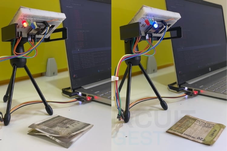
Real-World Performance Results
This picture clearly explains the working principle of the currency denomination recognition system practically. As seen in the setup, the ESP32-CAM is fixed at a precise and stable angle, allowing it to continuously monitor a defined area where the currency note is placed. When a ₹500 note is positioned under the camera, the system captures the image, processes it using the trained recognition model, and correctly identifies the denomination. Upon correct recognition, the red LED glows, providing a clear visual confirmation that the ₹500 note has been recognised.
Similarly, when a ₹20 note is placed in the same position, the system again captures the image under identical lighting and angle conditions. The distinct visual features of the ₹20 note are analysed, and once the denomination is correctly identified, the blue LED glows.
Practical Applications of ESP32 Currency Recognition
Assistive Technology for the Visually Impaired
By combining this system with audio output, it can help visually impaired individuals identify Indian currency denominations easily and independently. Even though visually impaired individuals can identify currency notes by touch, the sensitivity and accuracy of tactile recognition are often limited, especially for worn, damaged, or similar-sized notes. This limitation can lead to confusion and errors.
Retail and Point-of-Sale Systems
Retail shops can use this system to verify Indian currency during transactions, minimising human errors and speeding up the billing process.Automated Currency Counters
Shops, Banks and financial institutions can use this system to count and classify currency notes automatically, reducing manual effort and saving time.Vending Machine
This system can be integrated into vending machines to automatically recognise inserted currency notes and validate the denomination, enabling accurate product dispensing without human intervention
Future Enhancements for ESP32 Currency Recognition
This system can be further enhanced in several ways to improve functionality, usability and real-world applicability.
Support for more denominations, like Indian coins and more Indian currency. This can be improved to detect fake currency by training the model with both genuine and fake currency images.
An LCD or OLED display can be added to visually display the detected currency denominations.
By integrating a speaker or buzzer with voice playback, this system can announce the detected currency denomination. This feature would greatly benefit the visually impaired persons.
Troubleshooting Common ESP32 Currency Recognition Issues
The common issues that may occur while building or running the ESP32-CAM-based Indian Currency Recognition System, along with their possible causes and solutions.
Issue 1: ESP32-CAM Code Upload Failure
If the ESP32-CAM fails to upload the program, the most common reason is that GPIO0 is not connected to GND during the upload process or the incorrect board and COM port are selected in the Arduino IDE. To resolve this, connect GPIO0 to GND before starting the upload, select the AI Thinker ESP32-CAM board, choose the correct COM port, and press the RESET button when the upload begins.
Issue 2: No Output in Serial Monitor
When no data appears in the Serial Monitor, the issue is usually caused by an incorrect baud rate or improper TX and RX connections. Ensure that the Serial Monitor baud rate is set to 115200, verify that TX of the USB-to-Serial converter is connected to RX of the ESP32-CAM and RX to TX, and press the RESET button after opening the Serial Monitor.
Issue 3: ESP32-CAM Not Connecting to Wi-Fi
If the ESP32-CAM does not connect to Wi-Fi, it is often due to incorrect network credentials or the use of a 5 GHz Wi-Fi network, which is unsupported. Recheck the SSID and password in the code, confirm that a 2.4 GHz network is used, and keep the device close to the router for stable connectivity.
Issue 4: Web Server Not Opening in Browser
When the ESP32-CAM web interface does not load, the problem may be an incorrect IP address or a network mismatch. Check the IP address displayed in the Serial Monitor and ensure that the accessing device is connected to the same Wi-Fi network. Restarting the ESP32-CAM and refreshing the browser can also help.
Issue 5: Camera Not Detected or Black Image
A black image or camera detection failure usually indicates an incorrect camera model selection or a loose camera ribbon cable. Make sure that the camera model is defined as CAMERA_MODEL_AI_THINKER in the code and that the camera cable is firmly inserted. Restart the ESP32-CAM after verifying the connection.
Technical Summary and GitHub Repository
Access all project resources, including complete code, high-resolution wiring diagrams, demonstration videos, and additional documentation through this organised GitHub repository:


Frequently Asked Questions - ESP32-CAM Currency Recognition
⇥ 1. Why is Edge Impulse used in this project?
Edge Impulse simplifies the entire TinyML workflow, including data collection, labelling, model training, optimisation, and deployment. It allows even beginners to build and deploy AI models on resource-constrained devices like the ESP32-CAM with minimal complexity.
⇥ 2. Can this system work without an internet connection?
Yes, after the deployment of the final Arduino code, the internet won't be required, but to collect the images by the server and to train the model, you need the internet.
⇥ 3. How many images are required for good accuracy?
At least 50 images per currency denomination are recommended. Increasing the number of images, using different angles, lighting conditions, and backgrounds will be helpful in increasing the accuracy.
⇥ 4. Why is a plain background recommended during image capture?
The plain background helps to recognise the different denominations perfectly without any errors. The white background is suitable for every denomination.
⇥ 5. Which ESP32-CAM board is supported in this project?
This project is implemented using the AI Thinker ESP32-CAM module. Make sure to select and configure CAMERA_MODEL_AI_THINKER in the code before uploading.
⇥ 6. Can this system detect fake currency notes?
The current setup only detects the different denominations, not fake or real notes, but in future it may be implemented.
⇥ 7. What are the tips to improve currency recognition using ESP32-CAM?
Increase accuracy by using different images for training with more than 100 images per denomination, using uniform lighting, keeping a steady camera position, using a simple background, and incorporating damaged banknotes into your data set. Refit your model with problematic images and set parameters for best performance on Edge Impulse.
⇥ 8. What are the requirements of WiFi in currency recognition using ESP32, and how to use it?
The ESP32-CAM only supports 2.4 GHz WiFi during the initialisation and image acquisition process. Once it has been programmed and is ready for use as a currency detector model, WiFi is no longer required. It works offline as it has no use for an internet connection.
Conclusion for Currency Recognition System
This project demonstrates real-time ESP32-CAM currency recognition and Edge Impulse. The use of the Edge Impulse simplifies the complete development process, including data collection, labelling, model training, optimisation and deployment. This ESP32 currency recognition programming approach creates a foundation for numerous practical applications, including assistive technology, retail automation, and financial services. The integration of LED indicators provides an immediate visual representation of the detected denomination, and the serial monitor output helps in analysing prediction results and debugging the system efficiently. If you need more ideas about ESP32-CAM, do check our interesting project, WiFi Controlled Surveillance Robot Car using ESP32-CAM Module. Start building your ESP32-CAM currency recognition system today and explore the expanding possibilities of embedded artificial intelligence.
Each project builds on the ESP32 currency recognition programming skills you've developed, demonstrating the versatility of edge AI in solving real-world problems through accessible, affordable embedded systems.
I hope you found this project helpful and gained some new knowledge. If you have any questions, feel free to ask in the comments or join our CircuitDigest forum for a further in-depth conversation. For more ESP32 project ideas, take a look at our dedicated page.
Related ESP32-CAM Projects
Explore essential ESP32-CAM projects that bring machine vision to life. These projects are perfect for makers, IoT enthusiasts, and anyone looking to level up their embedded systems skills with practical, camera-driven applications.

Battery-Powered Attendance System Using Face Recognition on ESP32-CAM Board
So, in this tutorial, we are going to build an Attendance system using Face Recognition by leveraging the power of the ESP-32 CAM board. Along with the ESP32-CAM board, we will have an integrated power supply with 5-volt and 3.3-volt outputs that is powered by a 18650 cell.
")
How to use ESP32 CAM for Automatic Number Plate Recognition (ANPR)
In this tutorial, we'll give you step-by-step instructions with a circuit diagram and code to walk you through capturing an image of a car or bike, sending it to a cloud server that uses AI to recognise the license plate, and retrieving the decoded characters back to the ESP32-CAM.

Build your own Security Camera using ESP32
In this blog, we're going to show you how to build your own Simple CCTV Security Camera using an ESP32 camera module. From tinkering with hardware connections to coding functionalities and enabling remote access, join us on a step-by-step tutorial to craft a cost-effective and customizable surveillance solution.
Complete Project Code
/* Edge Impulse Arduino examples
* Copyright (c) 2022 EdgeImpulse Inc.
*
* Permission is hereby granted, free of charge, to any person obtaining a copy
* of this software and associated documentation files (the "Software"), to deal
* in the Software without restriction, including without limitation the rights
* to use, copy, modify, merge, publish, distribute, sublicense, and/or sell
* copies of the Software, and to permit persons to whom the Software is
* furnished to do so, subject to the following conditions:
*
* The above copyright notice and this permission notice shall be included in
* all copies or substantial portions of the Software.
*
* THE SOFTWARE IS PROVIDED "AS IS", WITHOUT WARRANTY OF ANY KIND, EXPRESS OR
* IMPLIED, INCLUDING BUT NOT LIMITED TO THE WARRANTIES OF MERCHANTABILITY,
* FITNESS FOR A PARTICULAR PURPOSE AND NONINFRINGEMENT. IN NO EVENT SHALL THE
* AUTHORS OR COPYRIGHT HOLDERS BE LIABLE FOR ANY CLAIM, DAMAGES OR OTHER
* LIABILITY, WHETHER IN AN ACTION OF CONTRACT, TORT OR OTHERWISE, ARISING FROM,
* OUT OF OR IN CONNECTION WITH THE SOFTWARE OR THE USE OR OTHER DEALINGS IN THE
* SOFTWARE.
*/
// These sketches are tested with 2.0.4 ESP32 Arduino Core
// https://github.com/espressif/arduino-esp32/releases/tag/2.0.4
/* Includes ---------------------------------------------------------------- */
#include <Currency_Detection_inferencing.h>
#include "edge-impulse-sdk/dsp/image/image.hpp"
#include "esp_camera.h"
// Select camera model - find more camera models in camera_pins.h file here
// https://github.com/espressif/arduino-esp32/blob/master/libraries/ESP32/…
//#define CAMERA_MODEL_ESP_EYE // Has PSRAM
#define CAMERA_MODEL_AI_THINKER // Has PSRAM
#if defined(CAMERA_MODEL_ESP_EYE)
#define PWDN_GPIO_NUM    -1
#define RESET_GPIO_NUM   -1
#define XCLK_GPIO_NUM    4
#define SIOD_GPIO_NUM    18
#define SIOC_GPIO_NUM    23
#define Y9_GPIO_NUM      36
#define Y8_GPIO_NUM      37
#define Y7_GPIO_NUM      38
#define Y6_GPIO_NUM      39
#define Y5_GPIO_NUM      35
#define Y4_GPIO_NUM      14
#define Y3_GPIO_NUM      13
#define Y2_GPIO_NUM      34
#define VSYNC_GPIO_NUM   5
#define HREF_GPIO_NUM    27
#define PCLK_GPIO_NUM    25
#elif defined(CAMERA_MODEL_AI_THINKER)
#define PWDN_GPIO_NUM     32
#define RESET_GPIO_NUM    -1
#define XCLK_GPIO_NUM      0
#define SIOD_GPIO_NUM     26
#define SIOC_GPIO_NUM     27
#define Y9_GPIO_NUM       35
#define Y8_GPIO_NUM       34
#define Y7_GPIO_NUM       39
#define Y6_GPIO_NUM       36
#define Y5_GPIO_NUM       21
#define Y4_GPIO_NUM       19
#define Y3_GPIO_NUM       18
#define Y2_GPIO_NUM        5
#define VSYNC_GPIO_NUM    25
#define HREF_GPIO_NUM     23
#define PCLK_GPIO_NUM     22
#else
#error "Camera model not selected"
#endif
/* Constant defines -------------------------------------------------------- */
#define EI_CAMERA_RAW_FRAME_BUFFER_COLS           320
#define EI_CAMERA_RAW_FRAME_BUFFER_ROWS           240
#define EI_CAMERA_FRAME_BYTE_SIZE                 3
/* Private variables ------------------------------------------------------- */
static bool debug_nn = false; // Set this to true to see e.g. features generated from the raw signal
static bool is_initialised = false;
uint8_t *snapshot_buf; //points to the output of the capture
static camera_config_t camera_config = {
   .pin_pwdn = PWDN_GPIO_NUM,
   .pin_reset = RESET_GPIO_NUM,
   .pin_xclk = XCLK_GPIO_NUM,
   .pin_sscb_sda = SIOD_GPIO_NUM,
   .pin_sscb_scl = SIOC_GPIO_NUM,
   .pin_d7 = Y9_GPIO_NUM,
   .pin_d6 = Y8_GPIO_NUM,
   .pin_d5 = Y7_GPIO_NUM,
   .pin_d4 = Y6_GPIO_NUM,
   .pin_d3 = Y5_GPIO_NUM,
   .pin_d2 = Y4_GPIO_NUM,
   .pin_d1 = Y3_GPIO_NUM,
   .pin_d0 = Y2_GPIO_NUM,
   .pin_vsync = VSYNC_GPIO_NUM,
   .pin_href = HREF_GPIO_NUM,
   .pin_pclk = PCLK_GPIO_NUM,
   //XCLK 20MHz or 10MHz for OV2640 double FPS (Experimental)
   .xclk_freq_hz = 20000000,
   .ledc_timer = LEDC_TIMER_0,
   .ledc_channel = LEDC_CHANNEL_0,
   .pixel_format = PIXFORMAT_JPEG, //YUV422,GRAYSCALE,RGB565,JPEG
   .frame_size = FRAMESIZE_QVGA,    //QQVGA-UXGA Do not use sizes above QVGA when not JPEG
   .jpeg_quality = 12, //0-63 lower number means higher quality
   .fb_count = 1,       //if more than one, i2s runs in continuous mode. Use only with JPEG
   .fb_location = CAMERA_FB_IN_PSRAM,
   .grab_mode = CAMERA_GRAB_WHEN_EMPTY,
};
/* Function definitions ------------------------------------------------------- */
bool ei_camera_init(void);
void ei_camera_deinit(void);
bool ei_camera_capture(uint32_t img_width, uint32_t img_height, uint8_t *out_buf) ;
/**
* @brief      Arduino setup function
*/
void setup()
{
   // put your setup code here, to run once:
   Serial.begin(115200);
   //comment out the below line to start inference immediately after upload
   while (!Serial);
   Serial.println("Edge Impulse Inferencing Demo");
   if (ei_camera_init() == false) {
       ei_printf("Failed to initialize Camera!\r\n");
   }
   else {
       ei_printf("Camera initialized\r\n");
   }
   ei_printf("\nStarting continious inference in 2 seconds...\n");
   ei_sleep(2000);
}
/**
* @brief      Get data and run inferencing
*
* @param[in]  debug  Get debug info if true
*/
void loop()
{
   // instead of wait_ms, we'll wait on the signal, this allows threads to cancel us...
   if (ei_sleep(5) != EI_IMPULSE_OK) {
       return;
   }
   snapshot_buf = (uint8_t*)malloc(EI_CAMERA_RAW_FRAME_BUFFER_COLS * EI_CAMERA_RAW_FRAME_BUFFER_ROWS * EI_CAMERA_FRAME_BYTE_SIZE);
   // check if allocation was successful
   if(snapshot_buf == nullptr) {
       ei_printf("ERR: Failed to allocate snapshot buffer!\n");
       return;
   }
   ei::signal_t signal;
   signal.total_length = EI_CLASSIFIER_INPUT_WIDTH * EI_CLASSIFIER_INPUT_HEIGHT;
   signal.get_data = &ei_camera_get_data;
   if (ei_camera_capture((size_t)EI_CLASSIFIER_INPUT_WIDTH, (size_t)EI_CLASSIFIER_INPUT_HEIGHT, snapshot_buf) == false) {
       ei_printf("Failed to capture image\r\n");
       free(snapshot_buf);
       return;
   }
   // Run the classifier
   ei_impulse_result_t result = { 0 };
   EI_IMPULSE_ERROR err = run_classifier(&signal, &result, debug_nn);
   if (err != EI_IMPULSE_OK) {
       ei_printf("ERR: Failed to run classifier (%d)\n", err);
       return;
   }
   // print the predictions
   ei_printf("Predictions (DSP: %d ms., Classification: %d ms., Anomaly: %d ms.): \n",
               result.timing.dsp, result.timing.classification, result.timing.anomaly);
#if EI_CLASSIFIER_OBJECT_DETECTION == 1
   ei_printf("Object detection bounding boxes:\r\n");
   for (uint32_t i = 0; i < result.bounding_boxes_count; i++) {
       ei_impulse_result_bounding_box_t bb = result.bounding_boxes[i];
       if (bb.value == 0) {
           continue;
       }
       ei_printf("  %s (%f) [ x: %u, y: %u, width: %u, height: %u ]\r\n",
               bb.label,
               bb.value,
               bb.x,
               bb.y,
               bb.width,
               bb.height);
   }
   // Print the prediction results (classification)
#else
   ei_printf("Predictions:\r\n");
   for (uint16_t i = 0; i < EI_CLASSIFIER_LABEL_COUNT; i++) {
       ei_printf("  %s: ", ei_classifier_inferencing_categories[i]);
       ei_printf("%.5f\r\n", result.classification[i].value);
   }
#endif
   // Print anomaly result (if it exists)
#if EI_CLASSIFIER_HAS_ANOMALY
   ei_printf("Anomaly prediction: %.3f\r\n", result.anomaly);
#endif
#if EI_CLASSIFIER_HAS_VISUAL_ANOMALY
   ei_printf("Visual anomalies:\r\n");
   for (uint32_t i = 0; i < result.visual_ad_count; i++) {
       ei_impulse_result_bounding_box_t bb = result.visual_ad_grid_cells[i];
       if (bb.value == 0) {
           continue;
       }
       ei_printf("  %s (%f) [ x: %u, y: %u, width: %u, height: %u ]\r\n",
               bb.label,
               bb.value,
               bb.x,
               bb.y,
               bb.width,
               bb.height);
   }
#endif

   free(snapshot_buf);
}
/**
* @brief   Setup image sensor & start streaming
*
* @retval  false if initialisation failed
*/
bool ei_camera_init(void) {
   if (is_initialised) return true;
#if defined(CAMERA_MODEL_ESP_EYE)
 pinMode(13, INPUT_PULLUP);
 pinMode(14, INPUT_PULLUP);
#endif
   //initialize the camera
   esp_err_t err = esp_camera_init(&camera_config);
   if (err != ESP_OK) {
     Serial.printf("Camera init failed with error 0x%x\n", err);
     return false;
   }
   sensor_t * s = esp_camera_sensor_get();
   // initial sensors are flipped vertically and colors are a bit saturated
   if (s->id.PID == OV3660_PID) {
     s->set_vflip(s, 1); // flip it back
     s->set_brightness(s, 1); // up the brightness just a bit
     s->set_saturation(s, 0); // lower the saturation
   }
#if defined(CAMERA_MODEL_M5STACK_WIDE)
   s->set_vflip(s, 1);
   s->set_hmirror(s, 1);
#elif defined(CAMERA_MODEL_ESP_EYE)
   s->set_vflip(s, 1);
   s->set_hmirror(s, 1);
   s->set_awb_gain(s, 1);
#endif
   is_initialised = true;
   return true;
}
/**
* @brief      Stop streaming of sensor data
*/
void ei_camera_deinit(void) {
   //deinitialize the camera
   esp_err_t err = esp_camera_deinit();
   if (err != ESP_OK)
   {
       ei_printf("Camera deinit failed\n");
       return;
   }
   is_initialised = false;
   return;
}

/**
* @brief      Capture, rescale and crop image
*
* @param[in]  img_width     width of output image
* @param[in]  img_height    height of output image
* @param[in]  out_buf       pointer to store output image, NULL may be used
*                           if ei_camera_frame_buffer is to be used for capture and resize/cropping.
*
* @retval     false if not initialised, image captured, rescaled or cropped failed
*
*/
bool ei_camera_capture(uint32_t img_width, uint32_t img_height, uint8_t *out_buf) {
   bool do_resize = false;
   if (!is_initialised) {
       ei_printf("ERR: Camera is not initialized\r\n");
       return false;
   }
   camera_fb_t *fb = esp_camera_fb_get();
   if (!fb) {
       ei_printf("Camera capture failed\n");
       return false;
   }
  bool converted = fmt2rgb888(fb->buf, fb->len, PIXFORMAT_JPEG, snapshot_buf);
  esp_camera_fb_return(fb);
  if(!converted){
      ei_printf("Conversion failed\n");
      return false;
  }
   if ((img_width != EI_CAMERA_RAW_FRAME_BUFFER_COLS)
       || (img_height != EI_CAMERA_RAW_FRAME_BUFFER_ROWS)) {
       do_resize = true;
   }
   if (do_resize) {
       ei::image::processing::crop_and_interpolate_rgb888(
       out_buf,
       EI_CAMERA_RAW_FRAME_BUFFER_COLS,
       EI_CAMERA_RAW_FRAME_BUFFER_ROWS,
       out_buf,
       img_width,
       img_height);
   }

   return true;
}
static int ei_camera_get_data(size_t offset, size_t length, float *out_ptr)
{
   // we already have a RGB888 buffer, so recalculate offset into pixel index
   size_t pixel_ix = offset * 3;
   size_t pixels_left = length;
   size_t out_ptr_ix = 0;
   while (pixels_left != 0) {
       // Swap BGR to RGB here
       // due to https://github.com/espressif/esp32-camera/issues/379
       out_ptr[out_ptr_ix] = (snapshot_buf[pixel_ix + 2] << 16) + (snapshot_buf[pixel_ix + 1] << 8) + snapshot_buf[pixel_ix];
       // go to the next pixel
       out_ptr_ix++;
       pixel_ix+=3;
       pixels_left--;
   }
   // and done!
   return 0;
}
#if !defined(EI_CLASSIFIER_SENSOR) || EI_CLASSIFIER_SENSOR != EI_CLASSIFIER_SENSOR_CAMERA
#error "Invalid model for current sensor"
#endif
