

In this project, we are going to build an ESP32 Cam Surveillance Car—a practical and accessible starting point to start learning about remote-controlled and ESP32 projects. This project leverages the versatility of the ESP32 camera module, offering a budget-friendly, energy-efficient and easy-to-make solution. Designed with simplicity and functionality in mind, it's an ideal starting point for newcomers to start learning web controls and the WiFi functionality of ESP32. If you are an ESP32 CAM fan you can also check out our other ESP32 CAM projects which we have built earlier.
This complete project was made possible by the sponsor for this article NextPCB, who also provided the PCB prototype for this project. Will discuss more on how to order your PCBs from NextPCB later in this article.
Feature Of ESP32 Cam Surveillance Car
Based on ESP32 Cam Module.
Easy to build.
No need for any additional remote control, can be controlled via web controls.
Low-cost design.
Easy to find components.
Fully open source.
Compact and Portable.
Easy upgradability.
Scalable.
Components Required to Build the ESP32 Cam Surveillance Car
The components required to build the DIY ESP32 Cam Surveillance Car are listed below. The exact value of each component can be found in the schematics or the BOM.
ESP32 Camera Module Module – x1
CH340K USB - UART controller – x1
TP4056 Li-ion charger IC – x1
MX1508 motor driver module – x1
AO3401 P - MOSFET – x1
Type C USB Connector 16Pin – x1
LiPo Battery – x1
N20 Motor – x4
44mm N20 Motor Wheel – x4
SMD resistors and capacitors
SMD LEDs
Slide Switch
Connectors
Custom PCB
Mounting screws
Other tools and consumables.
Approximate Build Cost
Here is the approximate build cost for the ESP32 Cam Surveillance Car. Keep in mind that the costs provided here are not exact and may vary depending on the vendor. The prices are calculated based on the cheapest options available from reputed vendors, with only the bare minimum number of components as the minimum MOQ.
| Components | ₹ 100.00 |
| ESP32 Cam | ₹ 450.00 |
| MX1508 Motor driver module | ₹ 40.00 |
| N20 Motors + 44mm wheels | ₹ 200.00 |
| Battery | ₹ 100.00 |
| PCB | ₹ 100.00 |
| Total | ₹ 990.00 |
ESP32 Cam Surveillance Car Circuit Diagram
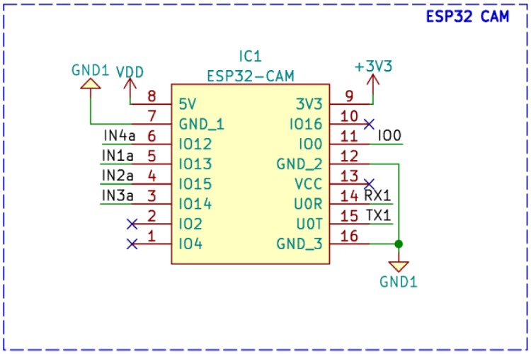
Now let’s look at the circuit diagram. The circuit itself is very simple and easily understandable. We have divided the entire circuit into different sections.

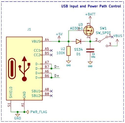
Here the first section contains the USB type C port along with the power path controller MOSFET and the power switch. The USB port serves two purposes, programming the ESP32 module and charging the battery. For turning on and off the device we have chosen a PCB mountable slide switch. The slide switch we have chosen is capable of handling up to 3A of DC current.
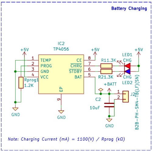
The next section contains the battery charger circuit. The battery charger circuit is built around the infamous TP4056 charge controller chip. The circuit contains charging and full charge indicators for displaying charging information. The charging current can be adjusted by changing the programming resistor RProg, which is connected to the prog pin of TP4056.
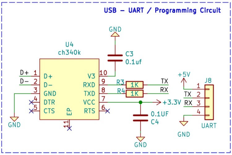
The Programming circuit consists of a CH340K chip, which is a very compact and cheap USB-UART converter chip. You can also use any other similar USB to the UART controller chips such as CP2102, FT232Rl or CH340G/C for the same purpose. But we choose the K variant because of its compact size and very minimal external component requirement. If you’re ESP32 Cam module comes with a built-in USB to UART converter you can use that to program your module and keep this section unpopulated. We have also provided a standard UART connector in case you want to use an external USB to UART converter module.
The ESP32 module itself is placed on a breakable PCB and we are using header pins to connect it to the main PCB. this ensures that we don’t need any additional support material or modifications to keep the camera in the correct position.
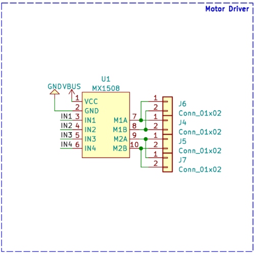
For driving the motor, we have used an MX1508 motor driver module. As we used a module, we don’t need any additional components for driving the motor. The module is placed on the PCB using header pins and then the motor using the JST connectors in the main PCB.
PCB for ESP32 Cam Surveillance Car
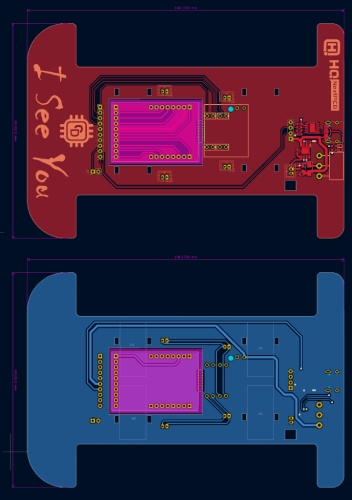
For this project, we have decided to make a custom PCB. We have designed the PCB in a way that it will serve multiple purposes, It will not only interconnect all the modules and components, but it will also act as a chassis for the ESP32 Cam Surveillance Car. The PCB is designed with KiCad. All the design files are available to download from the GitHub repo linked below this article. The PCB has a dimension of approximately 146mm x 99mm. Here are the top and bottom layers of the PCB.
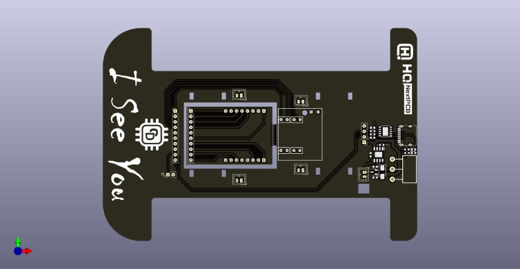
And here is the 3D view of the PCB.

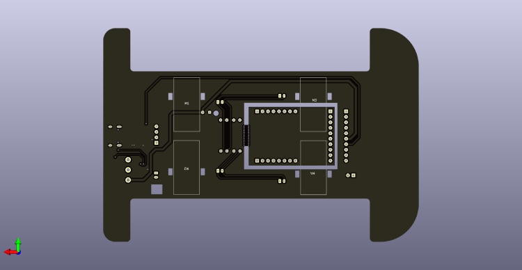
Here is the 3D preview of the ESP32 Cam Surveillance Car.

Ordering PCB from HQPCB
Now after finalizing the design, you can proceed with ordering the PCB:
Step 1: Get into https://www.nextpcb.com/ and sign up if this is your first time. Then, in the PCB Quote tab, upload the Gerber file, and the tool will automatically populate the PCB dimensions. Now make any changes you need such as PCB colour, Silkscreen, PCB thickness, and the number of PCBs etc.
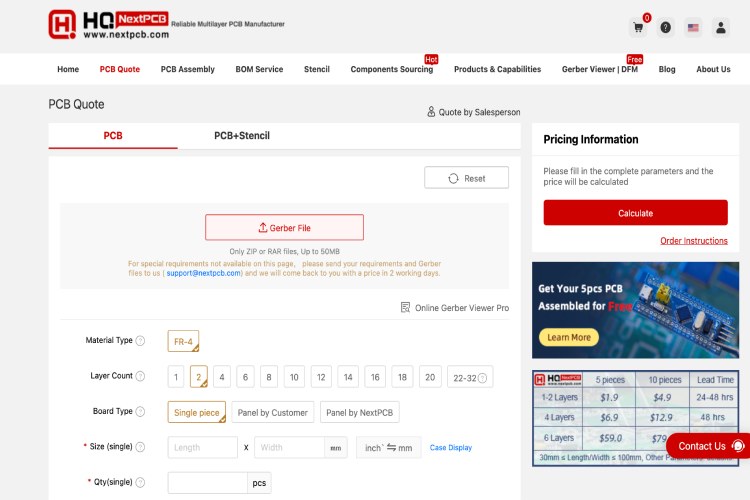
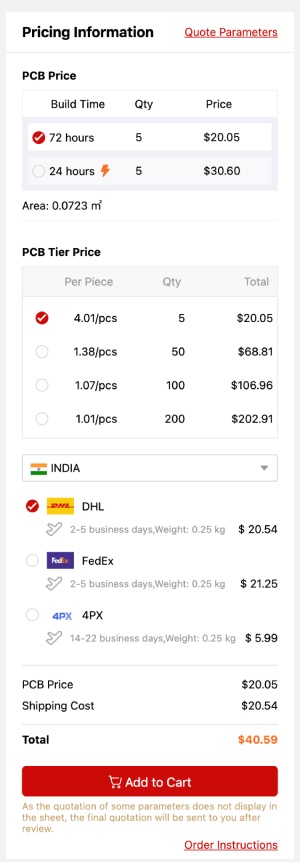
Step 2: Once all the required parameters are set click on calculate to generate the quote. The tool will show the build time, Cost and shipping costs of different shipping methods. Select the appropriate shipping method and click on add cart to proceed with the order.
Step 3: In the cart select the PCB we have just added and click on proceed. Give the shipping and billing details and then proceed with the payment. Once the payment is done the HQ PCB will start manufacturing your order. With in a week, you will receive the finished PCB.
Apart from PCB prototype NextPCB also provides a free Gerber Viewer and PCB assembly services, you can check them out if you are interested.
Assembling the ESP32 Cam Surveillance Car
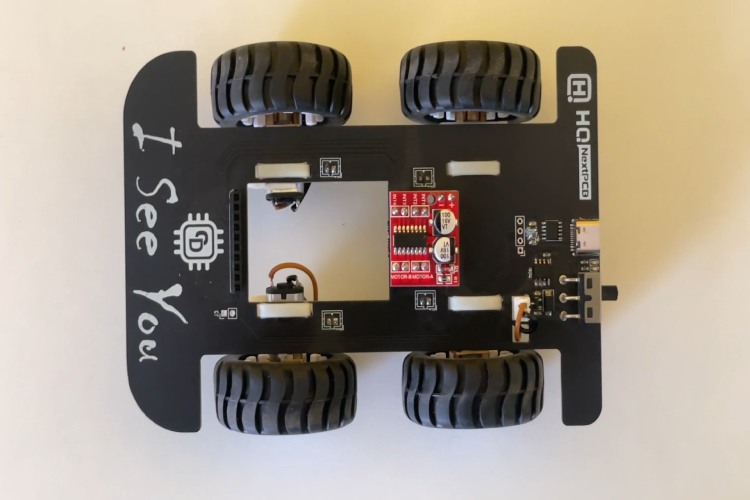
Once the PCBs are delivered, gather all other required components and start assembling the ESP32 Cam Surveillance Car. For soldering it is recommended to use a temperature-controlled soldering station. Start with the SMD components first. Once soldered all the SMD components start assembling the modules and connectors. Once all the components are soldered, plug in the modules connect to the PC and make sure you are able to communicate with the the ESP32 Cam module. Now secure the N20 motors to the PCB using cable ties, utilizing the holes provided in the PCB. Do the same for the battery. Make sure everything is secured and then couple the wheels to the motor shafts. Here is the image of a fully assembled ESP32 Cam Surveillance Car
ESP32 Cam Surveillance Car Arduino Code
Now that we have successfully built the ESP32 Cam Surveillance Car let’s program it. For the first let’s look at the code itself. As usual, make sure you have installed the ESP32 core for the Arduino IDE and all the necessary libraries. For this project, the external libraries we need to install are the AsyncTCP and the ESPAsyncWebserver. While using the ino file make sure the page.h file is also placed in the very same directory as the Arduino sketch. At first, we included all the necessary header files and declared all the global variables we needed. Change the SSID and password to your desired SSID and password. Then we created an Asychwebserver instance and two sockets for the controls and the video stream.
#include "esp_camera.h"
#include <Arduino.h>
#include <WiFi.h>
#include <AsyncTCP.h>
#include <ESPAsyncWebServer.h>
#include <iostream>
#include <sstream>
#include "page.h"
#define UP 1
#define DOWN 2
#define LEFT 3
#define RIGHT 4
#define STOP 0
#define RIGHT_MOTOR 0
#define LEFT_MOTOR 1
#define FORWARD 1
#define BACKWARD -1
float gap ;
int i;
int j;
int k;
//Camera related constants
#define PWDN_GPIO_NUM     32
#define RESET_GPIO_NUM    -1
#define XCLK_GPIO_NUM      0
#define SIOD_GPIO_NUM     26
#define SIOC_GPIO_NUM     27
#define Y9_GPIO_NUM       35
#define Y8_GPIO_NUM       34
#define Y7_GPIO_NUM       39
#define Y6_GPIO_NUM       36
#define Y5_GPIO_NUM       21
#define Y4_GPIO_NUM       19
#define Y3_GPIO_NUM       18
#define Y2_GPIO_NUM        5
#define VSYNC_GPIO_NUM    25
#define HREF_GPIO_NUM     23
#define PCLK_GPIO_NUM     22
const char* ssid     = "circuitdigest";
const char* password = "circuitdigest";
// Change according to your setup
extern int gpLb =  15; // Left 1
extern int gpLf = 13; // Left 2
extern int gpRb = 14; // Right 1
extern int gpRf = 2; // Right 2
extern int gpLed =  4; // Light
AsyncWebServer server(80);
AsyncWebSocket wsCamera("/Camera");
AsyncWebSocket wsCarInput("/CarInput");
uint32_t cameraClientId = 0;
The WheelAct function writes the PWM to each motor control pin based on the values transferred to it. The movecar function is responsible for calling the Wheelact function and passing appropriate values to it depending on the control signals from the web page.
void WheelAct(int nLf, int nLb, int nRf, int nRb)
{
analogWrite(gpLf, nLf);
analogWrite(gpLb, nLb);
analogWrite(gpRf, nRf);
analogWrite(gpRb, nRb);
}
void moveCar(int inputValue)
{
 Serial.printf("Got value as %d\n", inputValue);
 switch(inputValue)
 {
   case UP:
     delay(10);
     WheelAct(0, 250, 0, 250);
     break;
    case DOWN:
     WheelAct(250, 0, 250, 0);
     break;
    case LEFT:
     delay(10);
     WheelAct(0, 250, 250, 0);
     break;
    case RIGHT:
     delay(10);
     WheelAct(250, 0, 0, 250);
     break;
   case STOP:
     WheelAct(0, 0, 0, 0);
     break;

   default:
     WheelAct(0, 0, 0, 0);
     break;
 }
}
The following functions are responsible for the web control and the video stream. The handle root function handles the root web request by sending the webpage when requested. The onCarInputWebsocketEvent function handles the control signals from the web controls. When it is triggered it decodes the incoming socket message and sets the variables accordingly.
void handleRoot(AsyncWebServerRequest *request)
{
 request->send_P(200, "text/html", htmlHomePage);
}
void handleNotFound(AsyncWebServerRequest *request)
{
   request->send(404, "text/plain", "File Not Found");
}
void onCarInputWebSocketEvent(AsyncWebSocket *server,
                     AsyncWebSocketClient *client,
                     AwsEventType type,
                     void *arg,
                     uint8_t *data,
                     size_t len)
{
 switch (type)
 {
   case WS_EVT_CONNECT:
     Serial.printf("WebSocket client #%u connected from %s\n", client->id(), client->remoteIP().toString().c_str());
     break;
   case WS_EVT_DISCONNECT:
     Serial.printf("WebSocket client #%u disconnected\n", client->id());
     moveCar(0);
     ledcWrite(PWMLightChannel, 0);
     break;
   case WS_EVT_DATA:
     AwsFrameInfo *info;
     info = (AwsFrameInfo*)arg;
     if (info->final && info->index == 0 && info->len == len && info->opcode == WS_TEXT)
     {
       std::string myData = "";
       myData.assign((char *)data, len);
       std::istringstream ss(myData);
       std::string key, value;
       std::getline(ss, key, ',');
       std::getline(ss, value, ',');
       Serial.printf("Key [%s] Value[%s]\n", key.c_str(), value.c_str());
       int valueInt = atoi(value.c_str());
       if (key == "MoveCar")
       {
         moveCar(valueInt);
       }
       else if (key == "Light")
       {
         analogWrite(gpLed, valueInt);
       }
     }
     break;
   case WS_EVT_PONG:
   case WS_EVT_ERROR:
     break;
   default:
     break;
 }
}
The onCameraWebsocketEvent function handles the video stream. Whenever a client is connected or disconnected this function sets up the camera stream to the client.
void onCameraWebSocketEvent(AsyncWebSocket *server,
                     AsyncWebSocketClient *client,
                     AwsEventType type,
                     void *arg,
                     uint8_t *data,
                     size_t len)
{
 switch (type)
 {
   case WS_EVT_CONNECT:
     Serial.printf("WebSocket client #%u connected from %s\n", client->id(), client->remoteIP().toString().c_str());
     cameraClientId = client->id();
     break;
   case WS_EVT_DISCONNECT:
     Serial.printf("WebSocket client #%u disconnected\n", client->id());
     cameraClientId = 0;
     break;
   case WS_EVT_DATA:
     break;
   case WS_EVT_PONG:
   case WS_EVT_ERROR:
     break;
   default:
     break;
 }
}
As the name indicates the setupCamera function is responsible for configuring the ESP32 camera. This function contains all the configuration routines for the camera and it initializes the camera during booting.
void setupCamera()
{
 camera_config_t config;
 config.ledc_channel = LEDC_CHANNEL_0;
 config.ledc_timer = LEDC_TIMER_0;
 config.pin_d0 = Y2_GPIO_NUM;
 config.pin_d1 = Y3_GPIO_NUM;
 config.pin_d2 = Y4_GPIO_NUM;
 config.pin_d3 = Y5_GPIO_NUM;
 config.pin_d4 = Y6_GPIO_NUM;
 config.pin_d5 = Y7_GPIO_NUM;
 config.pin_d6 = Y8_GPIO_NUM;
 config.pin_d7 = Y9_GPIO_NUM;
 config.pin_xclk = XCLK_GPIO_NUM;
 config.pin_pclk = PCLK_GPIO_NUM;
 config.pin_vsync = VSYNC_GPIO_NUM;
 config.pin_href = HREF_GPIO_NUM;
 config.pin_sscb_sda = SIOD_GPIO_NUM;
 config.pin_sscb_scl = SIOC_GPIO_NUM;
 config.pin_pwdn = PWDN_GPIO_NUM;
 config.pin_reset = RESET_GPIO_NUM;
 config.xclk_freq_hz = 20000000;
 config.pixel_format = PIXFORMAT_JPEG;
  config.frame_size = FRAMESIZE_VGA;
 config.jpeg_quality = 10;
 config.fb_count = 1;
 // camera init
 esp_err_t err = esp_camera_init(&config);
 if (err != ESP_OK)
 {
   Serial.printf("Camera init failed with error 0x%x", err);
   return;
 }
 //drop down frame size for higher initial frame rate
 sensor_t * s = esp_camera_sensor_get();
 s->set_framesize(s, FRAMESIZE_CIF);
 s->set_vflip(s, 1);
 s->set_hmirror(s, 1);
 if (psramFound())
 {
   heap_caps_malloc_extmem_enable(20000);
   Serial.printf("PSRAM initialized. malloc to take memory from psram above this size");
 }
}
void sendCameraPicture()
{
 if (cameraClientId == 0)
 {
   return;
 }
 unsigned long  startTime1 = millis();
 //capture a frame
 camera_fb_t * fb = esp_camera_fb_get();
 if (!fb)
 {
     Serial.println("Frame buffer could not be acquired");
     return;
 }
 unsigned long  startTime2 = millis();
 wsCamera.binary(cameraClientId, fb->buf, fb->len);
 esp_camera_fb_return(fb);
 while (true)
 {
   AsyncWebSocketClient * clientPointer = wsCamera.client(cameraClientId);
   if (!clientPointer || !(clientPointer->queueIsFull()))
   {
     break;
   }
   delay(1);
 }
  unsigned long  startTime3 = millis();
 Serial.printf("Time taken Total: %d|%d|%d\n",startTime3 - startTime1, startTime2 - startTime1, startTime3-startTime2 );
}
The next functions setups the motor control and LED controls pins as outputs. As an initial value, this function sets these pins and logic low to prevent the motors from being activated as soon as the module is powered on.
void setUpPinModes()
{
 pinMode(gpLb, OUTPUT); //Left Backward
 pinMode(gpLf, OUTPUT); //Left Forward
 pinMode(gpRb, OUTPUT); //Right Forward
 pinMode(gpRf, OUTPUT); //Right Backward
 pinMode(gpLed, OUTPUT); //Light
 //initialize
 digitalWrite(gpLb, LOW);
 digitalWrite(gpLf, LOW);
 digitalWrite(gpRb, LOW);
 digitalWrite(gpRf, LOW);
 digitalWrite(gpLed, LOW);
}
Next, we have the setup function. As usual, it handles and calls all the necessary functions during startup. It calls the setUpPinmode function, followed by setting up a WiFi hotspot and tagging all the web handlers.
void setup(void)
{
 setUpPinModes();
 Serial.begin(115200);
 WiFi.softAP(ssid, password);
 IPAddress IP = WiFi.softAPIP();
 Serial.print("AP IP address: ");
 Serial.println(IP);
 server.on("/", HTTP_GET, handleRoot);
 server.onNotFound(handleNotFound);
 wsCamera.onEvent(onCameraWebSocketEvent);
 server.addHandler(&wsCamera);
 wsCarInput.onEvent(onCarInputWebSocketEvent);
 server.addHandler(&wsCarInput);
 server.begin();
 Serial.println("HTTP server started");
 setupCamera();
}
The loop functions manage the image stream in conjunction with the send Camera image function and also the control inputs.
void loop()
{
 wsCamera.cleanupClients();
 wsCarInput.cleanupClients();
 sendCameraPicture();
}
Using ESP32 Cam Surveillance Car
Once the code is compiled and uploaded to the ESP32 Cam module, turn the switch off and disconnect it from the PC. Now connect all the motors to the PCB using the provided connectors. Then switch on the ESP32 Cam Surveillance Car using the slide switch. The ESP32 will create an access point with the SSID and password provided in the code. The default SSID and Password are ‘circuitdigest’. Connect your smartphone to the access point using these credentials. Once connected, open any browser on your phone and navigate to 192.168.4.1. It will open up a web page with the video stream and control buttons.
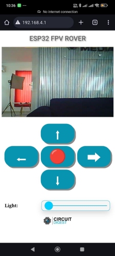
You can use these buttons to move the ESP32 Cam Surveillance Car in the desired direction. The light slider is used to control the LED on the ESP32 CAM module. You can turn it on and control its brightness using this slider. If you want to increase the range and performance use an external antenna for the ESP32. With the built-in PCB antenna, you may be limited with performance as well as the remote range.
Supporting Files
Here is the link to our GitHub repo, where you'll find the source code, schematics, and all other necessary files to build your own POV Display.


Complete Project Code
/*
* Project Name: Spy Rover
* Project Brief: Firmware for ESP32 based spy rover
* Author: Jobit Joseph
* Copyright © Jobit Joseph
* Copyright © Semicon Media Pvt Ltd
* Copyright © Circuitdigest.com
*
* This program is free software: you can redistribute it and/or modify
* it under the terms of the GNU General Public License as published by
* the Free Software Foundation, in version 3.
*
* This program is distributed in the hope that it will be useful,
* but WITHOUT ANY WARRANTY; without even the implied warranty of
* MERCHANTABILITY or FITNESS FOR A PARTICULAR PURPOSE. See the
* GNU General Public License for more details.
*
* You should have received a copy of the GNU General Public License
* along with this program. If not, see <http://www.gnu.org/licenses/>.
*
*/
#include "esp_camera.h"
#include <Arduino.h>
#include <WiFi.h>
#include <AsyncTCP.h>
#include <ESPAsyncWebServer.h>
#include <iostream>
#include <sstream>
#include "page.h"
#define UP 1
#define DOWN 2
#define LEFT 3
#define RIGHT 4
#define STOP 0
#define RIGHT_MOTOR 0
#define LEFT_MOTOR 1
#define FORWARD 1
#define BACKWARD -1
const int PWMFreq = 1000; /* 1 KHz */
const int PWMResolution = 8;
const int PWMSevoFreq = 50; /* 1 KHz */
const int PWMSevoResolution = 16;
const int PWMSpeedChannel = 6;
const int PWMLightChannel = 7;
const int PWMSevoChannel = 8;
float target_angle1=400 ; //상하
double servo_speed = 10;
float cur_angle1 = 400;
float gap ;
int i;
int j;
int k;
//Camera related constants
#define PWDN_GPIO_NUM 32
#define RESET_GPIO_NUM -1
#define XCLK_GPIO_NUM 0
#define SIOD_GPIO_NUM 26
#define SIOC_GPIO_NUM 27
#define Y9_GPIO_NUM 35
#define Y8_GPIO_NUM 34
#define Y7_GPIO_NUM 39
#define Y6_GPIO_NUM 36
#define Y5_GPIO_NUM 21
#define Y4_GPIO_NUM 19
#define Y3_GPIO_NUM 18
#define Y2_GPIO_NUM 5
#define VSYNC_GPIO_NUM 25
#define HREF_GPIO_NUM 23
#define PCLK_GPIO_NUM 22
const char* ssid = "circuitdigest";
const char* password = "circuitdigest";
// Change according to your setup
extern int gpLb = 15; // Left 1
extern int gpLf = 13; // Left 2
extern int gpRb = 14; // Right 1
extern int gpRf = 2; // Right 2
extern int gpLed = 4; // Light
AsyncWebServer server(80);
AsyncWebSocket wsCamera("/Camera");
AsyncWebSocket wsCarInput("/CarInput");
uint32_t cameraClientId = 0;
void WheelAct(int nLf, int nLb, int nRf, int nRb);
void moveCar(int inputValue)
{
Serial.printf("Got value as %d\n", inputValue);
switch(inputValue)
{
case UP:
delay(10);
WheelAct(0, 250, 0, 250);
break;
case DOWN:
WheelAct(250, 0, 250, 0);
break;
case LEFT:
delay(10);
WheelAct(0, 250, 250, 0);
break;
case RIGHT:
delay(10);
WheelAct(250, 0, 0, 250);
break;
case STOP:
WheelAct(0, 0, 0, 0);
break;
default:
WheelAct(0, 0, 0, 0);
break;
}
}
void handleRoot(AsyncWebServerRequest *request)
{
request->send_P(200, "text/html", htmlHomePage);
}
void handleNotFound(AsyncWebServerRequest *request)
{
request->send(404, "text/plain", "File Not Found");
}
void onCarInputWebSocketEvent(AsyncWebSocket *server,
AsyncWebSocketClient *client,
AwsEventType type,
void *arg,
uint8_t *data,
size_t len)
{
switch (type)
{
case WS_EVT_CONNECT:
Serial.printf("WebSocket client #%u connected from %s\n", client->id(), client->remoteIP().toString().c_str());
break;
case WS_EVT_DISCONNECT:
Serial.printf("WebSocket client #%u disconnected\n", client->id());
moveCar(0);
ledcWrite(PWMLightChannel, 0);
break;
case WS_EVT_DATA:
AwsFrameInfo *info;
info = (AwsFrameInfo*)arg;
if (info->final && info->index == 0 && info->len == len && info->opcode == WS_TEXT)
{
std::string myData = "";
myData.assign((char *)data, len);
std::istringstream ss(myData);
std::string key, value;
std::getline(ss, key, ',');
std::getline(ss, value, ',');
Serial.printf("Key [%s] Value[%s]\n", key.c_str(), value.c_str());
int valueInt = atoi(value.c_str());
if (key == "MoveCar")
{
moveCar(valueInt);
}
else if (key == "Light")
{
analogWrite(gpLed, valueInt);
}
}
break;
case WS_EVT_PONG:
case WS_EVT_ERROR:
break;
default:
break;
}
}
void onCameraWebSocketEvent(AsyncWebSocket *server,
AsyncWebSocketClient *client,
AwsEventType type,
void *arg,
uint8_t *data,
size_t len)
{
switch (type)
{
case WS_EVT_CONNECT:
Serial.printf("WebSocket client #%u connected from %s\n", client->id(), client->remoteIP().toString().c_str());
cameraClientId = client->id();
break;
case WS_EVT_DISCONNECT:
Serial.printf("WebSocket client #%u disconnected\n", client->id());
cameraClientId = 0;
break;
case WS_EVT_DATA:
break;
case WS_EVT_PONG:
case WS_EVT_ERROR:
break;
default:
break;
}
}
void setupCamera()
{
camera_config_t config;
config.ledc_channel = LEDC_CHANNEL_0;
config.ledc_timer = LEDC_TIMER_0;
config.pin_d0 = Y2_GPIO_NUM;
config.pin_d1 = Y3_GPIO_NUM;
config.pin_d2 = Y4_GPIO_NUM;
config.pin_d3 = Y5_GPIO_NUM;
config.pin_d4 = Y6_GPIO_NUM;
config.pin_d5 = Y7_GPIO_NUM;
config.pin_d6 = Y8_GPIO_NUM;
config.pin_d7 = Y9_GPIO_NUM;
config.pin_xclk = XCLK_GPIO_NUM;
config.pin_pclk = PCLK_GPIO_NUM;
config.pin_vsync = VSYNC_GPIO_NUM;
config.pin_href = HREF_GPIO_NUM;
config.pin_sscb_sda = SIOD_GPIO_NUM;
config.pin_sscb_scl = SIOC_GPIO_NUM;
config.pin_pwdn = PWDN_GPIO_NUM;
config.pin_reset = RESET_GPIO_NUM;
config.xclk_freq_hz = 20000000;
config.pixel_format = PIXFORMAT_JPEG;
config.frame_size = FRAMESIZE_VGA;
config.jpeg_quality = 10;
config.fb_count = 1;
// camera init
esp_err_t err = esp_camera_init(&config);
if (err != ESP_OK)
{
Serial.printf("Camera init failed with error 0x%x", err);
return;
}
//drop down frame size for higher initial frame rate
sensor_t * s = esp_camera_sensor_get();
s->set_framesize(s, FRAMESIZE_CIF);
s->set_vflip(s, 1);
s->set_hmirror(s, 1);
if (psramFound())
{
heap_caps_malloc_extmem_enable(20000);
Serial.printf("PSRAM initialized. malloc to take memory from psram above this size");
}
}
void sendCameraPicture()
{
if (cameraClientId == 0)
{
return;
}
unsigned long startTime1 = millis();
//capture a frame
camera_fb_t * fb = esp_camera_fb_get();
if (!fb)
{
Serial.println("Frame buffer could not be acquired");
return;
}
unsigned long startTime2 = millis();
wsCamera.binary(cameraClientId, fb->buf, fb->len);
esp_camera_fb_return(fb);
//Wait for message to be delivered
while (true)
{
AsyncWebSocketClient * clientPointer = wsCamera.client(cameraClientId);
if (!clientPointer || !(clientPointer->queueIsFull()))
{
break;
}
delay(1);
}
unsigned long startTime3 = millis();
Serial.printf("Time taken Total: %d|%d|%d\n",startTime3 - startTime1, startTime2 - startTime1, startTime3-startTime2 );
}
void setUpPinModes()
{
pinMode(gpLb, OUTPUT); //Left Backward
pinMode(gpLf, OUTPUT); //Left Forward
pinMode(gpRb, OUTPUT); //Right Forward
pinMode(gpRf, OUTPUT); //Right Backward
pinMode(gpLed, OUTPUT); //Light
//initialize
digitalWrite(gpLb, LOW);
digitalWrite(gpLf, LOW);
digitalWrite(gpRb, LOW);
digitalWrite(gpRf, LOW);
digitalWrite(gpLed, LOW);
}
void WheelAct(int nLf, int nLb, int nRf, int nRb)
{
analogWrite(gpLf, nLf);
analogWrite(gpLb, nLb);
analogWrite(gpRf, nRf);
analogWrite(gpRb, nRb);
}
void setup(void)
{
setUpPinModes();
Serial.begin(115200);
WiFi.softAP(ssid, password);
IPAddress IP = WiFi.softAPIP();
Serial.print("AP IP address: ");
Serial.println(IP);
server.on("/", HTTP_GET, handleRoot);
server.onNotFound(handleNotFound);
wsCamera.onEvent(onCameraWebSocketEvent);
server.addHandler(&wsCamera);
wsCarInput.onEvent(onCarInputWebSocketEvent);
server.addHandler(&wsCarInput);
server.begin();
Serial.println("HTTP server started");
setupCamera();
}
void loop()
{
wsCamera.cleanupClients();
wsCarInput.cleanupClients();
sendCameraPicture();
// Serial.printf("SPIRam Total heap %d, SPIRam Free Heap %d\n", ESP.getPsramSize(), ESP.getFreePsram());
}

Hi i am unable to understand where the +5V is coming from and what voltage rated battery are you going to use....there doesnt seem to be 5v regulator in the circuit