

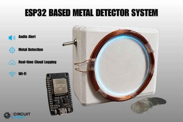
This tutorial shows us how to build our own functional DIY ESP32 metal detector from scratch using an affordable Wi-Fi enabled microcontroller, a handful of easily available electronic components, and a simple, hand-wound copper coil. Instead of relying on expensive, specialised sensors or complex industrial circuits, this PI metal detector circuit project uses basic hobbyist parts to build a standalone locator.
We will be guided through winding our own induction coil, assembling the simple pulse switch circuit on a zero PCB, and flashing the code for this DIY Pulse Induction metal detector. Best of all, it features built-in smartphone monitoring over a local web dashboard, allowing us to view real-time target data and depth estimation wirelessly on any phone browser. You can also check out similar ESP32 Projects and IoT projects done previously here at Circuit Digest.
Quick Summary: What This Project Covers
✓ Detection method: Pulse Induction (PI) - better performance in mineralised soil than VLF detectors
✓ Controller: ESP32 Dev Kit (dual-core: Core 1 samples the coil, Core 0 hosts the dashboard)
✓ Detection range - Up to 10cm, calibrated via two reference points (0cm and 2cm)
✓ Monitoring- Live phone-based web dashboard over Wi-Fi hotspot, no app install needed
✓ Enclosure - Custom 3D-printed two-part housing (STL files included)
✓ Build cost: Uses common hobbyist parts - no specialised detector ICs required
Table of Contents
How Does This DIY ESP32 Metal Detector Work?
This project uses the Pulse Induction method for metal detection. This circuit sends a pulse from the ESP32 to our hand-wound copper coil. After some time, the pulse is suddenly cut off, which produces a magnetic field near the coil. When there is no metal near the coil, the magnetic field collapses instantly, causing the voltage to decay rapidly. However, when a metal object is nearby, the collapsing magnetic field induces an Eddy Current in the metal target. This eddy current generates its own secondary magnetic field, which counteracts the decay and slows the overall decay rate, leaving a measurable voltage that remains above our threshold.
The ESP32 then reads the rate of decay using the ADC pin. At the same time, the ESP32 also handles the hosting of the hotspot and web server, where we can monitor the metal detector. Once the circuit is turned ON, we need to connect our phone to the ESP32's WiFi hotspot, type the IP address which is displayed in the serial monitor in Chrome browser and click Enter. The monitoring webpage will open, and from there, we can monitor the metal detector. Here is another Arduino Metal Detector project where we showcased how a metal detector is integrated with Arduino Nano.
Live Demonstration: See How It Actually Works
From concept to reality, watch the complete system in action. This live demonstration highlights the project's actual working process. Explore its features, performance, and real-world operation. See how the design transforms innovative ideas into practical solutions.
Components Required for the DIY ESP32 Metal Detector
Below is the list of components required to build this PI metal detector circuit, with their specifications.
| S.no | Components | Specification | Quantity |
| 1. | Microcontroller | ESP32 Dev Kit | 1 |
| 2. | Resistor | 200Ω, 220Ω | 1 |
| 3. | Capacitor | 0.1 nF (Ceramic) | 1 |
| 4. | Copper Wire | 0.3 mm-0.5 mm enamelled copper wire | 6.5 Meters |
| 5. | Buzzer | 3.3 V Passive buzzer | 1 |
| 6. | LED | 3.3 V LED | 1 |
| 7. | Battery | 18650 3.7V battery | 1 |
| 8. | Battery holder | 18650 battery holder | 1 |
| 9. | Battery Charging module | TP4056 (03962A) | 1 |
| 10. | Switch | Toggle Switch | 1 |
| 11. | Diode | IN4007 | 1 |
ESP32 Metal Detector Wiring Diagram
Below is the complete ESP32 metal detector wiring diagram for this Pulse Induction build.

This DIY Pulse Induction Metal Detector circuit is quite simple. One end of 200Ω resistor is connected to GPIO 26, the other end of the resistor is connected to the anode of the IN4007 diode, and one end of the search coil, which is wound by us from 25 to 30 turns with a diameter of 7cm.
ESP32 Metal Detector Pinout
| ESP32 Pin | Connected To | Function |
| GPIO 26 (pulsePin) | 200Ω resistor → coil + diode anode | Drives the coil pulse |
| GPIO 33 (capPin) | Diode cathode + 0.1nF capacitor | Reads decay voltage (ADC) |
| GPIO 2 (LED) | 220Ω resistor → LED anode | Target-detected status indicator |
| GPIO 4 (buz) | Passive buzzer control pin | Audible detection alert (PWM tone) |
| VIN / 5V | TP4056 OUT+ | Power input |
| GND | TP4056 OUT- / common ground | Common ground reference |
The inductance of our coil is around 98 μH, which is calculated using the formula below.
L = (μο * N^2 * A) / lWhere,
L- Inductance in Henries
μο- Permeability, it's 4π*10-7 for Air
N- Number of turns
A- Inner Core Area (πr2) in m2
l- Length of the Coil in meters
The Cathode of the diode is connected to GPIO 33 and 0.1 nF ceramic capacitors, one end, the other end of the 0.1 nF ceramic Capacitor is connected to the search coil's second end and the GND. The 3.7V battery's positive and negative terminals are connected to the B+ and B- terminals of the TP4056 Charging module, while the OUT+ is connected to the VIN or 5V pin of the ESP32 and the OUT- is connected to the GND pin of the ESP32. The 220Ω resistor's one end is connected to GPIO 2, and the other end is connected to the Anode of the LED; the Cathode of the LED is connected to the GND pin of the ESP32. The control pin of the buzzer is connected to GPIO 4, the VCC pin to the 3.3V pin and the GND pin to the ground pin of the ESP32. You can also check out the Simple Metal Detector Circuit, which is built without using any microcontrollers.
3D Printed Enclosure Design
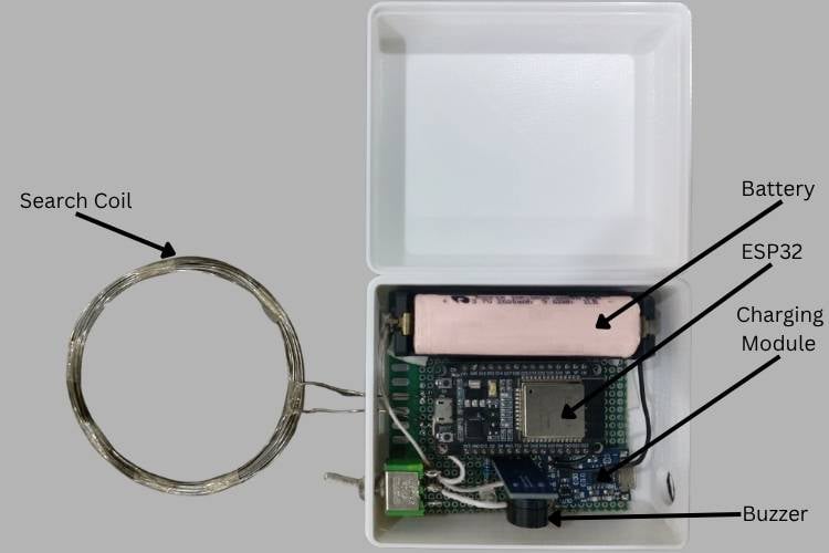
This project features a compact, custom-engineered two-part enclosure designed in Onshape to securely house all the electronics. The main body has overall dimensions of 81 mm x 96 mm x 45 mm (total height) and includes precise cutouts for system hardware: a 4 mm hole for the toggle power switch, an 11 mm slot for the USB Type-C charging port, and two 2 mm diameter holes to cleanly route the copper coil wire inside.

To print the housing, simply download the STL files for both enclosure parts and import them into any standard 3D slicer application like Cura or PrusaSlicer. Configure your preferred slicing profiles: 0.2 mm layer height and 20 infill to prepare the model for your machine. Finally, send the generated G-code to your 3D printer to create an enclosure.
Pulse Induction vs VLF: Choosing the Right Metal Detector Circuit
Before building, it helps to understand why this project uses a Pulse Induction circuit instead of the more common VLF (Very Low Frequency) design used in most consumer detectors.
| Parameter | Pulse Induction (PI) | VLF (Very Low Frequency) |
| Coil design | Single coil (transmit + receive) | Dual coil (separate transmit and receive) |
| Performance in mineralised soil | Excellent - largely unaffected | Poor - prone to false signals |
| Target discrimination | Limited (mainly presence + depth) | Good (can identify metal type) |
| Circuit complexity | Simple -ideal for DIY/hobbyist builds | Higher - needs precise dual-coil balancing |
Since this DIY ESP32 metal detector is designed to be straightforward to construct and is still highly accurate without using advanced discrimination circuitry, the single-coil PI method is ideal for amateur construction.
Code Explanation
The code is written in Arduino IDE for real-time metal detection and distance estimation using an ESP32 microcontroller, where core 1 serves as a sampling and dynamic baseline tracking and core 0 hosts a webpage securely.
I/O Pin Map & Buzzing Configuration
#include <WiFi.h>
#include <WebServer.h>
#define capPin    33
#define pulsePin  26
#define led       2
#define buz       4
#define THRESHOLD      80
#define GLITCH_FILTER  3
#define QUIET_RESYNC_LOOPS   40
// PWM SETTINGS FOR PASSIVE BUZZER
#define BUZ_FREQ         2500
#define BUZ_RESOLUTION   8
#define TON_DUTY_LOW     128
#define TON_DUTY_OFF     0
Distance Scaling Constant
This section imports the Wi-Fi and asynchronous libraries for the web dashboard. It maps the physical pins of ESP32, like capPin is GPIO 33, pulsePin is GPIO 26, LED pin is GPIO 2, and buzPin is GPIO 4. The THRESHOLD variable is used to control the sensitivity of the device, while GLITCH_FILTER is the number of sequential loops required for the buzzer to turn ON, and QUITE_RESYNC_LOOP is the number of loops required to set the baseline to re-zero. The other variables are used to control the buzzer frequency and tone.
const float CAL_DIFF_AT_0CM     = 900.0;
const float CAL_DIFF_AT_REF     = 140.0;
const float REF_DISTANCE_CM     = 2.0;
const float MAX_DISTANCE_CM     = 15.0;
const float SMOOTHING_ALPHA     = 0.20;
Asynchronous HTML/JS Web Dashboard
These settings calibrate the depth calculator by teaching the ESP32 what the signal looks like at 0cm(touching) and at 2 cm away. It uses these two points to guess the target's distance up to a maximum of 15 cm.
const char index_html[] PROGMEM = R"rawliteral(
<!DOCTYPE html>
<html>
<head>
   <meta name="viewport" content="width=device-width, initial-scale=1">
…..
   )rawliteral";
Depth Extraction Logic
This section stores our complete mobile-friendly webpage code directly into the ESP32’s flash memory using PROGMEM to save on dynamic RAM. The embedded JavaScript has an optimized background loop that uses the browser's async fetch() API to update metrics from your server every 150ms without a full reload of the webpage.
float diffToDistanceCm(float diffMag) {
   if (diffMag <= 1) diffMag = 1;
   const float r0 = 0.3;
   float k = CAL_DIFF_AT_0CM * pow(r0, 3.0);
   float kRef = CAL_DIFF_AT_REF * pow(REF_DISTANCE_CM, 3.0);
   k = (k + kRef) / 2.0;
   float distCm = pow(k / diffMag, 1.0 / 3.0);
   if (distCm < 0) distCm = 0;
   if (distCm > MAX_DISTANCE_CM) distCm = MAX_DISTANCE_CM;
   return distCm;
}
Adaptive Baseline Tracking Logic
In this section, the raw signal changes are converted into a physical measurement. This calculates an inverse-cube root math curve ( pow(..., 1.0 / 3.0 ) ) to give a very accurate linear centimeter depth reading.
if (!targetPresent) {
           quietLoops++;
           // Fast baseline correction when no metal is present
           localSumExpect = localSumExpect + ((long)sum - avgsum);
           if (quietLoops > QUIET_RESYNC_LOOPS * 16) {
               localSumExpect = ((long)sum) << 6;
               quietLoops = 0;
           }
       } else {
           quietLoops = 0;
           // Ultra-slow tracking when metal is present.
           // This prevents baseline lockup and allows the buzzer to turn off immediately when metal is removed.
           localSumExpect = localSumExpect + (((long)sum - avgsum) >> 3);
       }
High-speed Coil Pulsing Mechanism
This section handles the continuous monitoring inside the main loop on Core 1. When no metal is nearby, the baseline auto-corrects quickly to track changes. When metal is detected, instead of freezing entirely, this slow tracking prevents baseline lock-up and allows the detector to recover and silence the buzzer the moment metal is removed.
void applyPulses() {
   for (int i = 0; i < 3; i++) {
       digitalWrite(pulsePin, HIGH);
       delayMicroseconds(6);
       digitalWrite(pulsePin, LOW);
       delayMicroseconds(6);
   }
}
This function performs the core physics operation of the PI metal detector circuit. It makes the coil driver pin high and low exactly three times in 6 microsecond bursts. This rapid switching creates a sharp, momentary electromagnetic spike in our hand-wound copper coil, inducing the necessary eddy currents in nearby target metals to perform pulse induction scanning.
Output
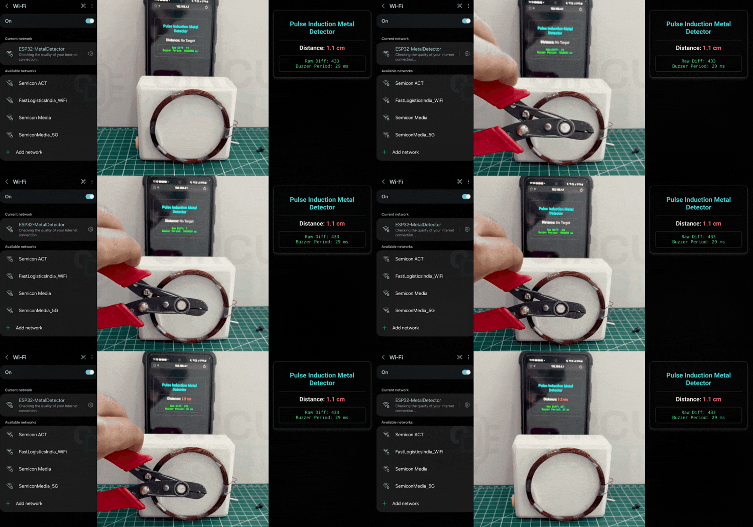
This detector has a web server that offers a live mobile dashboard of target presence, raw signal deviation (Diff) and centimeter depth estimates. The ESP32 also drives physical telemetry by triggering a passive buzzer to generate sound when metal is detected.
Troubleshooting the DIY ESP32 Metal Detector
1. What to do when small objects are not detected?
Fix: To detect the small object in this metal detector, we needed to reduce the THRESHOLD value in our code (e.g., lower it from 80 down to 50). This makes the software sensitive enough to catch tiny voltage changes from small coins or rings.
2. What to do when the coil is not detecting any size of metal?
Fix: Scrape the enamel coating off the wire ends. Enamelled wire has an invisible insulation layer. Use sandpaper or a utility knife to scratch both ends down before soldering to make this PI metal detector fully functional.
3. What to do when the system is glitching or beeping constantly?
Fix: Connect a Common Ground. Ensure a solid wire links the ESP32 GND pin directly to the Negative (-) terminal of our battery charging module so all components share the same zero voltage reference.
4. How to verify the coil is wound correctly?
Fix: Test continuity and resistance. Use a multimeter to check that the coil beeps from end to end (no breaks). The total resistance should be very low, typically between 0.5 Ω and 2 Ω
ESP32 Metal Detector GitHub
Find everything you need to recreate the ESP32 Metal Detector, including the source code, wiring details, and setup instructions. Clone the repository and start building your own detector today.


Learn ESP32 Through Real-World Projects
Build practical embedded systems with ESP32 by exploring projects focused on AI, voice interaction, and IoT. From converting speech into text using AI to designing a talking alarm clock and a smart energy meter with remote alerts, these projects provide valuable hands-on learning experiences.
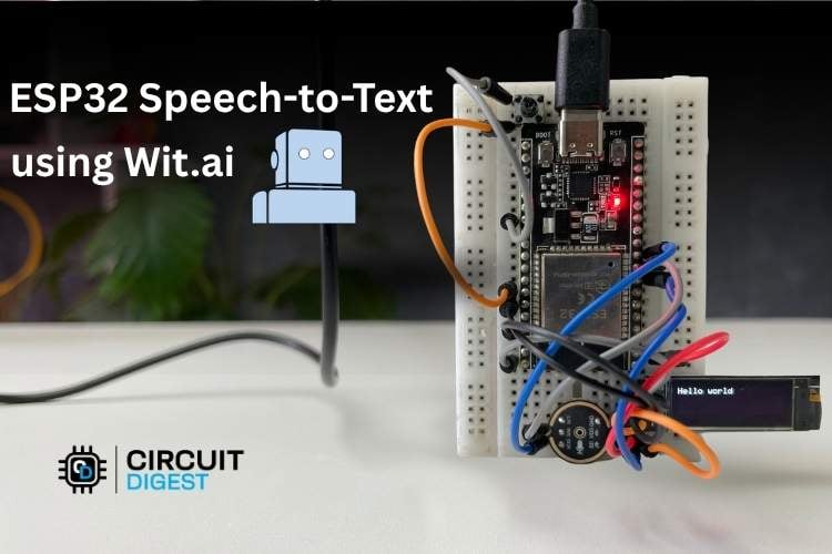
ESP32 Speech to Text Using AI- I2S Mic & Wit.ai API
In this project, we’ll be learning how to build an ESP32 Speech-to-Text system using an ESP32 development board. We’ll use an I2S MIC to record speech and an OLED display to display the converted text.
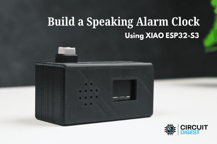
Build a Speaking Alarm Clock Using the XIAO ESP32-S3
The ESP32 speaking alarm clock built in this tutorial replaces the beep at a scheduled time and expects the user to interpret the reason for the beep. While functional, this approach lacks intelligence and context.
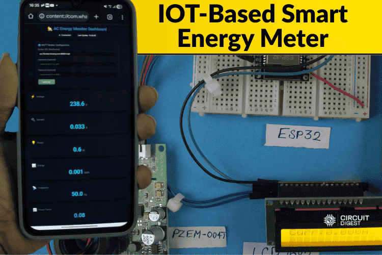
IoT-Based Smart Energy Meter With SMS Alert
This smart energy meter using IoT project mostly focuses on reducing the latency of the data and adding an important safety feature. Whenever the system detects abnormal conditions like low voltage, high current, or any unusual behaviour, an SMS alert is sent to the registered phone number.
Complete Project Code
/*
* Dual-Core Transient Decay Metal Detector for ESP32 with Web Server
* RECTIFIED v4.3 - RECOVERY & STUCK-BEEP LOGIC FIX
* - Configured for LOW-LEVEL PASSIVE BUZZER on GPIO 4 using New LEDC API
* - Features Continuous Adaptive Baseline Tracking to prevent stuck-beeping
*/
#include <WiFi.h>
#include <WebServer.h>
#define capPin    33
#define pulsePin  26
#define led       2
#define buz       4
#define THRESHOLD      80
#define GLITCH_FILTER  3
#define QUIET_RESYNC_LOOPS   40
// PWM SETTINGS FOR PASSIVE BUZZER
#define BUZ_FREQ         2500
#define BUZ_RESOLUTION   8
#define TON_DUTY_LOW     128
#define TON_DUTY_OFF     0
// ───────────────────────────────────────────────────────────
//DISTANCE CALIBRATION
// ───────────────────────────────────────────────────────────
const float CAL_DIFF_AT_0CM     = 900.0;
const float CAL_DIFF_AT_REF     = 140.0;
const float REF_DISTANCE_CM     = 2.0;
const float MAX_DISTANCE_CM     = 15.0;
const float SMOOTHING_ALPHA     = 0.20;
// WI-FI CREDENTIALS
const char* ssid = "ESP32-MetalDetector";
const char* password = "password123";
WebServer server(80);
TaskHandle_t DetectorTask = nullptr;
// Thread-safe shared states
volatile long sumExpect = 0;
volatile long diff = 0;
volatile unsigned long pTime = 0;
volatile long buzPeriod = 0;
volatile int webTargetPresent = 0;
volatile float webDistanceCm = -1;
volatile long lastDiffShared = 0;
portMUX_TYPE mux = portMUX_INITIALIZER_UNLOCKED;
void applyPulses();
void detectorLoop(void *pvParameters);
void handleRoot();
void handleData();
float diffToDistanceCm(float diffMag);
// HTML & JavaScript Dashboard Interface
const char index_html[] PROGMEM = R"rawliteral(
<!DOCTYPE html>
<html>
<head>
   <meta name="viewport" content="width=device-width, initial-scale=1">
   <title>ESP32 Metal Detector Dashboard</title>
   <style>
       body { font-family: Arial, sans-serif; text-align: center; background: #121212; color: #e0e0e0; padding: 20px; }
       .card { background: #1e1e1e; padding: 20px; border-radius: 12px; box-shadow: 0 4px 10px rgba(0,0,0,0.5); max-width: 450px; margin: 20px auto; border: 1px solid #333; }
       h1 { color: #00adb5; font-size: 24px; }
       .metric { font-size: 22px; font-weight: bold; margin: 15px 0; }
       .near { color: #ff4d4d; }
       .mid { color: #ffd700; }
       .far { color: #00ff66; }
       .none { color: #888; }
       .data-box { background: #111; padding: 10px; border-radius: 6px; font-family: monospace; font-size: 16px; margin-top: 10px; border: 1px solid #222; color: #00ff66; }
   </style>
</head>
<body>
   <div class="card">
       <h1>Pulse Induction Metal Detector</h1>
       <hr style="border-color:#333;">
       <div class="metric">Distance: <span id="distance" class="none">No Target</span></div>
       <div class="data-box">
           <div>Raw Diff: <span id="diffVal">0</span></div>
           <div>Buzzer Period: <span id="buzVal">0</span> ms</div>
       </div>
   </div>
   <script>
       setInterval(function() {
           fetch('/data')
           .then(response => response.json())
           .then(data => {
               document.getElementById("diffVal").innerText = data.diff;
               document.getElementById("buzVal").innerText = data.buzzer;
               let distEl = document.getElementById("distance");
               if (data.present === 1) {
                   distEl.innerText = data.cm.toFixed(1) + " cm";
                   if (data.cm < 2) distEl.className = "near";
                   else if (data.cm < 6) distEl.className = "mid";
                   else distEl.className = "far";
               } else {
                   distEl.innerText = "No Target";
                   distEl.className = "none";
               }
           })
           .catch(err => console.log(err));
       }, 150);
   </script>
</body>
</html>
)rawliteral";
void setup() {
   Serial.begin(115200);
   pinMode(pulsePin, OUTPUT);
   digitalWrite(pulsePin, LOW);
   pinMode(capPin, INPUT);
   pinMode(led, OUTPUT);
   digitalWrite(led, LOW);
   ledcAttach(buz, BUZ_FREQ, BUZ_RESOLUTION);
   ledcWrite(buz, TON_DUTY_OFF);
   analogReadResolution(10);
   WiFi.mode(WIFI_AP);
   WiFi.softAP(ssid, password);
   server.on("/", handleRoot);
   server.on("/data", handleData);
   server.begin();
   xTaskCreatePinnedToCore(
       detectorLoop,
       "DetectorTask",
       4096,
       NULL,
       1,
       &DetectorTask,
       1
   );
}
void loop() {
   server.handleClient();
   delay(2);
}
void handleRoot() {
   server.send_P(200, "text/html", index_html);
}
void handleData() {
   long diffLocal;
   long buzLocal;
   int presentLocal;
   float cmLocal;
   portENTER_CRITICAL(&mux);
   diffLocal = lastDiffShared;
   buzLocal = buzPeriod;
   presentLocal = webTargetPresent;
   cmLocal = webDistanceCm;
   portEXIT_CRITICAL(&mux);
   String json = "{";
   json += "\"diff\":" + String(diffLocal) + ",";
   json += "\"buzzer\":" + String(buzLocal) + ",";
   json += "\"present\":" + String(presentLocal) + ",";
   json += "\"cm\":" + String(cmLocal, 1);
   json += "}";
   server.send(200, "application/json", json);
}
float diffToDistanceCm(float diffMag) {
   if (diffMag <= 1) diffMag = 1;
   const float r0 = 0.3;
   float k = CAL_DIFF_AT_0CM * pow(r0, 3.0);
   float kRef = CAL_DIFF_AT_REF * pow(REF_DISTANCE_CM, 3.0);
   k = (k + kRef) / 2.0;
   float distCm = pow(k / diffMag, 1.0 / 3.0);
   if (distCm < 0) distCm = 0;
   if (distCm > MAX_DISTANCE_CM) distCm = MAX_DISTANCE_CM;
   return distCm;
}
void detectorLoop(void *pvParameters) {
   long localSumExpect = 0;
   int quietLoops = 0;
   int localGlitchCounter = 0;
   unsigned long localPTime = 0;
   float smoothedMag = 0;
   bool smoothInit = false;
   for (;;) {
       int minval = 1023;
       int maxval = 0;
       unsigned long sum = 0;
       for (int i = 0; i < 256; i++) {
           pinMode(capPin, OUTPUT);
           digitalWrite(capPin, LOW);
           delayMicroseconds(20);
           pinMode(capPin, INPUT);
           applyPulses();
           int val = analogRead(capPin);
           if (val < minval) minval = val;
           if (val > maxval) maxval = val;
           sum += val;
       }
       sum -= minval;
       sum -= maxval;
       if (localSumExpect == 0) {
           localSumExpect = ((long)sum) << 6;
       }
       long avgsum = (localSumExpect + 32) >> 6;
       long localDiff = (long)sum - avgsum;
       bool targetPresent = (labs(localDiff) >= THRESHOLD);
       // FIXED TRACKER LOGIC: Continuous baseline adaptation
       if (!targetPresent) {
           quietLoops++;
           // Fast baseline correction when no metal is present
           localSumExpect = localSumExpect + ((long)sum - avgsum);
           if (quietLoops > QUIET_RESYNC_LOOPS * 16) {
               localSumExpect = ((long)sum) << 6;
               quietLoops = 0;
           }
       } else {
           quietLoops = 0;
           // Ultra-slow tracking when metal is present.
           // This prevents baseline lockup and allows the buzzer to turn off immediately when metal is removed.
           localSumExpect = localSumExpect + (((long)sum - avgsum) >> 3);
       }
       if (targetPresent) {
           localGlitchCounter++;
       } else {
           localGlitchCounter = 0;
       }
       long localBuzPeriod = 1000000;
       int localPresent = 0;
       float localCm = -1;
       if (localGlitchCounter >= GLITCH_FILTER) {
           long magnitude = labs(localDiff);
           if (magnitude > 0) {
               localBuzPeriod = avgsum / (2 * magnitude);
           }
           if (localBuzPeriod > 300) localBuzPeriod = 300;
           unsigned long cTime = millis();
           bool buzOn = false;
           if (cTime < localPTime + 10) {
               buzOn = true;
           }
           if (cTime > localPTime + (unsigned long)localBuzPeriod) {
               buzOn = true;
               localPTime = cTime;
           }
           digitalWrite(led, buzOn ? HIGH : LOW);
           ledcWrite(buz, buzOn ? TON_DUTY_LOW : TON_DUTY_OFF);
           localPresent = 1;
           if (!smoothInit) {
               smoothedMag = (float)magnitude;
               smoothInit = true;
           } else {
               smoothedMag = (SMOOTHING_ALPHA * (float)magnitude) + ((1.0 - SMOOTHING_ALPHA) * smoothedMag);
           }
           localCm = diffToDistanceCm(smoothedMag);
       } else {
           digitalWrite(led, LOW);
           ledcWrite(buz, TON_DUTY_OFF);
           localBuzPeriod = 1000000;
           localPresent = 0;
           localCm = -1;
           smoothInit = false;
       }
       portENTER_CRITICAL(&mux);
       sumExpect = localSumExpect;
       diff = localDiff;
       buzPeriod = localBuzPeriod;
       webTargetPresent = localPresent;
       webDistanceCm = localCm;
       lastDiffShared = localDiff;
       pTime = localPTime;
       portEXIT_CRITICAL(&mux);
       vTaskDelay(pdMS_TO_TICKS(10));
   }
}
void applyPulses() {
   for (int i = 0; i < 3; i++) {
       digitalWrite(pulsePin, HIGH);
       delayMicroseconds(6);
       digitalWrite(pulsePin, LOW);
       delayMicroseconds(6);
   }
}

Comments 1
metal dedektörü için cep telefonundaki program nedir nasıl yüklenir
Add a comment
No account needed. Your comment appears once a moderator has reviewed it.