 Vedhathiri
Author

Ever thought about how you could monitor the household energy usage of your home remotely without heavy hardware or a complex setup? To make this idea practical, we came up with this project: an IoT based Smart Energy Meter using MQTT with SMS alert. Using the PZEM-004T sensor with ESP32, this smart energy meter using IoT provides real-time tracking of voltage, current, power consumption, and power factor through the MQTT protocol. This smart energy meter using IoT project mostly focuses on reducing the latency of the data and adding an important safety feature. Whenever the system detects abnormal conditions like low voltage, high current, or any unusual behaviour, an SMS alert is sent to the registered phone number. For this, we use a Circuit Digest Cloud account so we can receive the SMS free of cost. Also, explore our Smartphone-Controlled Home Appliances System with an Energy Meter using NodeMCU, which enables real-time tracking and remote control of household loads through a mobile application.
Table of Contents
Why Choose PZEM-004T for Your Smart Energy Meter Using IoT?
The PZEM-004T module stands out as the optimal choice for any IoT based smart energy meter project due to its factory-calibrated accuracy and integrated metering IC. The above image shows the PZEM-004T module with the external CT.
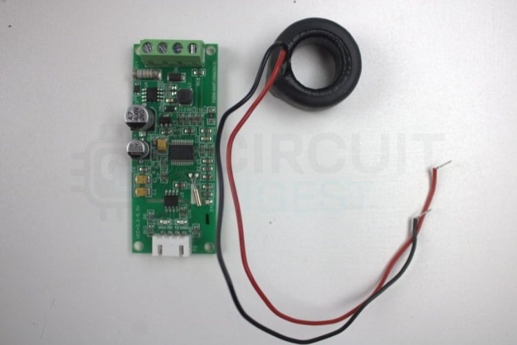
The PZEM-004T-100A is an AC energy-measuring module which is designed to measure the current, power, voltage, energy consumption, frequency, and power factor. This AC energy-measuring module provides comprehensive electrical parameter monitoring essential for building a complete smart energy meter using IoT. This module is commonly used in smart energy meters, domestic AC monitoring systems, home automation, and industrial load meters. While ZMPT101B voltage sensors and ACS712/SCT-013 current sensors require complex calibration and suffer from noise susceptibility, the PZEM-004T delivers factory-calibrated measurements. If you’re interested in exploring more innovative ideas in ESP32, be sure to check out our ESP32-based projects.
PZEM-004T Measurement Capabilities
Operating Principle of PZEM-004T in Smart Energy Meters
The PZEM-004T operates through a sophisticated measurement process essential for any IoT based smart energy meter:
- AC Voltage is detected with dedicated Terminal Blocks.
- Current is detected with an external Current Transformer CT (clamp) placed around the Phase Phase only, allowing for measurement of current through electromagnetic induction.
- Sampling of AC waveforms occurs within the internal metering IC to calculate electrical parameters.
- Processed measurement data is communicated using the UART Modbus Protocol to the ESP32 Microcontroller.
Voltage input is taken through the AC terminal block. The external CT sensor is placed around only the live wire to detect current. Module samples the AC waveform internally using its metering IC. It calculates voltage, current, power, energy, PF, and frequency. Then the microcontroller requests data through UART/Modbus, and the PZEM sends the measured values.
Understanding Current Transformer (CT) Technology
This image shows the Open-CT module
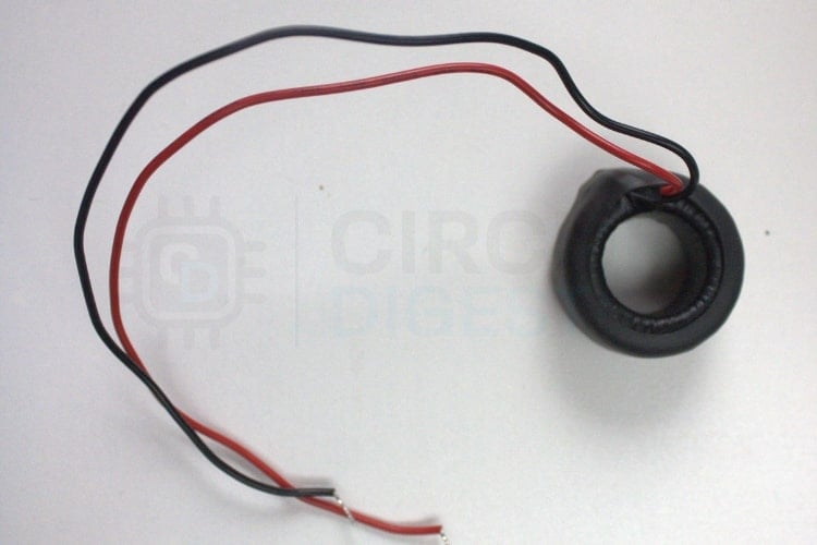
When AC flows through a wire, it generates a magnetic field around the conductor. The open CT has a split core that can be opened and placed around the wire. Inside the CT is a coil of wire that captures the changing magnetic field and produces a proportionally smaller AC. This small current is then measured by devices like the PZEM-004T to calculate the actual load current.
Components Required for IoT Based Smart Energy Meter
Building this IoT based smart energy meter project requires the following components for complete functionality:
| S.No | Components | Quantity | Purpose in Smart Energy Meter |
| 1 | ESP32 | 1 | Main microcontroller used for this project |
| 2 | I2C Module | 1 | Used to interface LCD with the ESP32 |
| 3 | LCD 16x2 | 1 | Displays current, voltage, power factor etc… |
| 4 | PZEM-004T(V4.0) | 1 | Measures the electrical parameters |
| 5 | External CT | 1 | Required for measuring current with PZEM |
| 6 | Breadboard | 1 | For connecting all components |
| 7 | Jumper Wires | Required amount | To make all necessary electrical connections |
| 8 | Arduino IDE(Software) | - | Used to program the energy meter system |
Smart Energy Meter Block Diagram Explained
The smart energy meter block diagram below illustrates the system architecture, showing how components interact for comprehensive energy tracking. This illustrates the block diagram of the smart energy meter using the ESP32.

∗ Power Source: Main AC Power Outlet connected via PZEM-004T Module.
∗ Current Sensing: External CT for measuring current, along with integrated voltage sensing.
∗ Microcontroller: Use of ESP32 for processing and transmitting data.
∗ LCD Display: Local tracking on a 16x2 display using an I2C Module.
∗ Remote Monitoring: WiFi-connected device sends MQTT for remote tracking.
∗ Alert System: Alerts are sent via SMS using the Circuit Digest Cloud API.
The above block diagram shows how various modules and the controller are integrated to form a system to get the desired output. The ESP32 is interfaced with PZEM-004T, which is connected to an external CT, load, and power supply. The PZEM-004T module itself handles the measurement of all electrical parameters. The processed data can be seen in the LCD, which is connected to the ESP32 and in the MQTT dashboard.
IoT Based Smart Energy Meter Circuit Diagram
Let’s discuss the circuit diagram of the IoT-based smart energy meter using MQTT with SMS alert. The IoT based smart energy meter circuit diagram below provides detailed connection instructions.

This circuit diagram shows the ESP32 connected to the PZEM-004T module, which measures the electrical parameters like voltage, current, power, energy, etc. Then the data collected from the PZEM module is processed by the ESP32, and that data is displayed in the LCD display, and the same data can be displayed in the MQTT dashboard.
Circuit Connection Details
This IoT based smart energy meter circuit diagram shows critical connections:
Hardware Assembly for Smart Energy Meter Using IoT
The image illustrates how the components are assembled in real time.
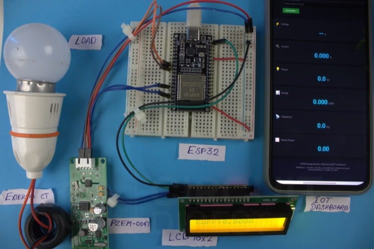
The hardware setup shows the PZEM-004T module, which measures the electrical parameters of the load and that data is transmitted to the ESP32. Then ESP32 processes the data and displays it in various ways, like Dashboard, LCD, Serial monitor, etc. The hardware setup demonstrates the practical implementation of the smart energy meter using IoT project.
Programming the Smart Energy Meter - Code Explanation
The ESP32 code initialises the required libraries and sets up Wi-Fi, MQTT, the LCD, and the PZEM energy sensor. It continuously reads electrical parameters from the sensor and publishes the data to an MQTT broker for remote tracking. At the same time, the values are shown on the LCD, and alerts such as SMS notifications are triggered when a condition is met.
The ESP32 firmware for this IoT based smart energy meter project integrates multiple functionalities for comprehensive energy tracking:
Library Initialization and Configuration
#include <Wire.h>
#include <LiquidCrystal_I2C.h>
#include <PZEM004Tv30.h>
#include <WiFi.h>
#include <PubSubClient.h>
#include <HTTPClient.h>
LiquidCrystal_I2C lcd(0x27, 16, 2);
HardwareSerial PZEMSerial(2);
PZEM004Tv30 pzem(PZEMSerial, 17, 16);
These libraries enable functions for the smart energy meter using IoT I2C LCD control, UART communication with PZEM, WiFi/MQTT connectivity, and HTTP requests for sending SMS alerts. Initialises the LCD at address 0x27 and assigns ESP32 UART pins (TX=17, RX=16) for communicating with the PZEM module.
Reading Electrical Parameters
float V = pzem.voltage();
float I = pzem.current();
float P = pzem.power();
float E = pzem.energy();
float F = pzem.frequency();
float PF = pzem.pf();
Reads all electrical values from the PZEM: voltage, current, power, total energy, frequency, and power factor during each loop cycle. The code continuously reads six critical electrical parameters from the PZEM module, forming the core data acquisition loop of this IoT based smart energy meter.
SMS Alert Implementation
String payload =
 "{\"mobiles\":\"" + String(mobileNumber) +
 "\",\"var1\":\"Energy meter\"" +
 ",\"var2\":\"High Voltage\"}";
The above is the Format of the SMS which will be received at the registered mobile number whenever the voltage is High. This SMS only triggers when the given condition is met.
if (V > 255) {
   if (millis() - lastSMS > smsCooldown) {
       sendSMS();
       lastSMS = millis();
   }
}
The above is the condition which is set in the code, which checks if the voltage is high, and sends an SMS only once per cooldown period to avoid repeated alerts.
Secure HTTPS Communication
void sendSMS() {
 WiFiClientSecure secureClient;
 secureClient.setInsecure();
 HTTPClient http;
 String apiUrl = "https://www.circuitdigest.cloud/api/v1/send_sms?ID=" + String(templateID);
 http.begin(secureClient, apiUrl);
 http.addHeader("Authorization", apiKey);
 http.addHeader("Content-Type", "application/json");
Creates a secure HTTP client, formats the API request, and prepares authorisation details needed by the SMS service.
LCD Display Rotation
lcd.clear();
lcd.print("Volt:"); lcd.print(V,1);
delay(2000);
Clears the screen and shows different readings (voltage, current, etc.) every 2 seconds for easy viewing. So this will give the output of all electrical parameters in order.
Dashboard Code Explanation for IoT Based Smart Energy Meter Project
The web-based dashboard enables remote tracking of your smart energy meter using IoT from any browser without authentication or backend infrastructure.
Steps to get the Dashboard
⇒ Step 1: Copy the Dashboard code from the GitHub repo. Paste it into the notepad which is available on your PC and save it as an .html file.
⇒ Step 2: Go to the file's saved location and right-click it. You can see the open in Chrome option, click that, and after this dashboard will be displayed like the one below.
The dashboard relies on a free public MQTT broker provided by HiveMQ, which eliminates the need for any backend server, account creation or any additional configuration. Since the broker is publicly accessible, the web dashboard can directly connect using MQTT over Websocket and subscribe to the required topics without modifying the source code. The dashboard will automatically receive the data and update the values in real time as long as the ESP32 is powered on and connected to the Wi-Fi. Since the broker is public, there is no authentication or encryption, meaning the data is not secure and can be accessed by anyone using the same topic names.
Dashboard UI Structure
<div class="card">
 <span id="voltage" class="value">--</span>
 <span class="unit">V</span>
</div>
The dashboard uses HTML and CSS to create a clean, modern, and responsive user interface. Data cards are designed to display electrical parameters such as voltage, current, power, energy, frequency, and power factor
MQTT Connection Configuration
<input type="text" id="broker-url"
value="ws://broker.hivemq.com:8000/mqtt">
The configuration panel allows users to connect the dashboard to an MQTT broker without modifying the code. It supports WebSocket-based MQTT connections, which are required for browser communication.
Real-Time Data Subscription
client.subscribe("unique/energy/voltage");
client.on("message",(topic,message)=>{
 voltage.innerText = message.toString();
});
Connection Status and Error Handling
Once connected, the dashboard subscribes to predefined MQTT topics published by the ESP32. Each topic corresponds to a specific electrical parameter such as voltage, current, or power. When new data arrives, the dashboard instantly updates the corresponding UI element.
client.on("error",(err)=>{
 showAlert(err.message);
});
The dashboard continuously monitors the MQTT connection status and displays it using colour-coded indicators. Error handling logic detects issues such as connection failures or timeouts and shows alert messages to the user.
Working Demonstration of IoT Based Smart Energy Meter
The ESP32 continuously reads voltage, current, power, frequency, and power factor from the PZEM-004T module via UART connection. The PZEM-004T handles the heavy metering calculations internally, reducing the processing load on the ESP32. The ESP32 receives and broadcasts data to both the MQTT dashboard and the LCD display. As a result, the project allows us to monitor data both locally and remotely. We used the MQTT dashboard instead of HTTP or other cloud apps. Because MQTT is a publish-subscribe protocol, it is ideal for streaming live sensor data. MQTT consumes less bandwidth than HTTP and has reduced latency. To test the SMS feature, we implemented a simple condition in the code. So once the criteria are met, the SMS function will be triggered, and the text message will be delivered to the specified phone number, which is mentioned in Circuit Digest Cloud website.
Why MQTT for This Smart Energy Meter Using IoT?
MQTT protocol offers distinct advantages for IoT based smart energy meter applications:
- The Publish-Subscribe Model works best for real-time streaming of sensor data to numerous receiving devices.
- The low bandwidth requirement means much less data usage than posting (polling) with HTTP.
- Low latency means that updates occur almost instantaneously; hence, there is no lag time between requests and responses.
- Having a persistent connection allows you to monitor your environment without losing connectivity.
- Quality of Service provides a means to create delivery assurances depending on the importance of the data.
If you need to know how to proceed with the SMS API generating feature, go through the Free SMS API.
Real-Life Dashboard for the Smart Energy Meter Using IoT
The following shows the real-time data, which is shown in the MQTT dashboard.
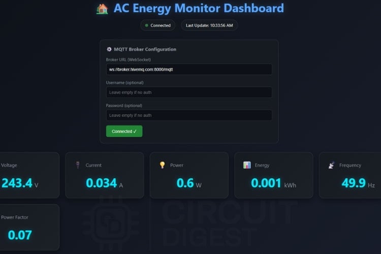
The dashboard shows the real-time electrical parameters like voltage, current, power, energy, frequency, and power factor. Each parameter updates in real-time as data arrives from the smart energy meter using IoT.
Multi-Interface Data Display
This shows the real-time data displayed across multiple interfaces for easier tracking.
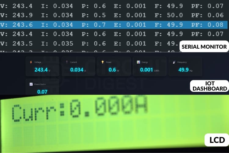
The image above shows live readings displayed in three locations: the Serial Monitor, the IOT dashboard, and the LCD screen. All three sources show the same data being collected from the energy meter in real time.
On the LCD screen, the values don’t stay on a single parameter. Instead, the display automatically goes through different readings like voltage, current, power factor, frequency, and power. This means the screen cycles through one parameter at a time in order, allowing you to keep track of every value without needing to press any buttons.
SMS Alert Functionality
This demonstrates how the message feature is triggered, and the message is sent to the mobile number.
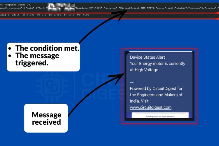
In this, we used a simple condition: if the voltage is High, then the condition is satisfied, which activates the message feature. The SMS is sent to the mobile number as shown in the picture above, allowing you to stay informed at any time.
Application of IoT Based Smart Energy Meter
This application of IoT based smart energy meter extends across residential, commercial, and industrial sectors:
Electricity Monitoring
This system can be used in households to monitor the energy consumption in real-time. Users can monitor the voltage, power, current, and power factor usage at anytime they want.Safety and Fault Detection
The SMS alert feature helps to detect the abnormal conditions, such as voltage present without current flow, sudden drops, etc. This early detection can help to prevent electrical accidents, asset loss, etc.Smart Home Automation
The system can serve as the base for: Predictive maintenance, Automatic load control and Energy-efficient automationRemote Energy Management
Through MQTT-based monitoring, users can check the status of their electrical system from anywhere and at any time. This makes it useful for tracking : Vacation homes or Remote installations
Troubleshooting Common Issues in Smart Energy Meter Projects
This helps identify and resolve common issues that may occur while building or testing the IoT-Based Smart Energy Meter with SMS Alert.
When voltage is displayed correctly but current always reads zero, it typically means there is no sufficient load connected or the CT clamp is not fully closed; connecting a higher-power load and firmly closing the CT usually resolves this issue.
In case the PZEM-004T shows zero or incorrect values, the issue is often caused by clamping the current transformer around both live and neutral wires or by incorrect UART connections; make sure the CT is placed only on the live wire and oriented correctly toward the load.
If the LCD does not display any readings, it is usually due to an incorrect I2C address or loose SDA and SCL connections; this can be fixed by scanning the I2C bus to confirm the address (commonly 0x27 or 0x3F) and ensuring SDA is connected to GPIO21 and SCL to GPIO22 on the ESP32.
Conclusion: Building Your Smart Energy Meter Using IoT
This IoT based smart energy meter project shows a practical and simple IoT-based system for real-time energy tracking. By integrating the PZEM-004T sensor with an ESP32 microcontroller and utilising the MQTT protocol, the system effectively measures electrical parameters such as voltage, current, power, and power factor and displays them both locally on an LCD and remotely via a dashboard. A significant enhancement to the system is the SMS alert feature, which uses the Circuit Digest Cloud API to notify users instantly of abnormal conditions, such as the presence of voltage without current flow. This adds a valuable layer of safety and awareness for households. The choice of MQTT over HTTP contributes to lower latency and reduced bandwidth usage, making the system suitable for reliable, real-time data streaming. With its simple hardware setup, clear circuit design, and functional code implementation, this smart energy meter using IoT project offers an accessible and effective solution for anyone looking to monitor energy usage remotely while maintaining awareness of system integrity through timely alerts. Also, check our DIY Power Consumption Monitoring Device using ESP32 to get an idea about the energy monitoring sensors.
GitHub Repository and Source Files
Access the complete source code, circuit diagrams, and documentation for this IoT Based Smart Energy Meter with SMS Alert.


Working Video: Smart Energy Meter Using IoT
Demonstration showing real-time energy monitoring with remote data display and alert notifications for abnormal electrical conditions.
Frequently Asked Questions About IoT Based Smart Energy Meter
⇥ 1. Which hardware components are used in this project?
The main components are:
• ESP32 microcontroller
• PZEM-004T module
• LCD display with I2C
• Internet connectivity via Wi-Fi
• Connecting wires and breadboard
⇥ 2. Why did we use MQTT here instead of HTTP?
MQTT is lightweight and uses less bandwidth compared to HTTP. Also, the latency of the MQTT is comparatively less than that of HTTP.
⇥ 3. How does the SMS alert feature work?
The system uses the Circuit Digest Cloud's API to send the SMS, we have implemented a condition in the code; if the condition is met, it will trigger the SMS.
⇥ 4. What kind of abnormal conditions can the system detect?
It can detect issues like:
• Voltage present but no current flow
• power loss
• Overload conditions such as high current or high voltage, etc...
⇥ 5. Is Wi-Fi required for SMS alerts?
Yes. The ESP32 sends SMS using Circuit Digest Cloud API over the internet, so Wi-Fi access is required for the alert function.
⇥ 6. Is the system safe to use with mains electricity?
Yes, the PZEM-004T module is designed for mains measurement and keeps the high-voltage side isolated from the ESP32 so it will not affect the microcontroller.
⇥ 7. Will it be possible to add this smart energy meter to existing home automation systems?
Yes, it is possible. The MQTT protocol allows for ease of integration with Home Assistant, OpenHAB, Node-RED, or other custom automation systems. To add energy data to the automation rules, the dashboard, and/or control logic on your home automation system, simply subscribe to the topics published by this smart energy meter.
This tutorial was created by the CircuitDigest engineering team. Our experts focus on creating practical, hands-on tutorials to help makers and engineers learn Raspberry Pi projects, Arduino projects, IoT development projects and more.
I hope you liked this article and learned something new from building a smart energy meter using IoT. If you have any doubts, you can ask in the comments below or use our CircuitDigest forum for a detailed discussion.
Related ESP32 Camera Projects
Previously, we have used ESP32 CAM to build many interesting projects. If you want to know more about those topics, links are given below.

Mask Detection System using ESP32 Cam and M5Stack Core2
In this project, we will make a device to detect if a person is wearing a mask and has a healthy heart rate using M5Stack Core2, ESP32-CAM, AWS IoT, and Edge Impulse.

Smart Video Doorbell using ESP32 Cam
This Smart Wi-Fi Video Doorbell using ESP32-CAM can be powered by an AC socket, and whenever someone at the door presses the doorbell button, it will play a specific song on your phone and send a text message with a link of video streaming page where you can see the person at the door from anywhere in the world.

Smart Car Washing System Using Edge Impulse for Object Detection
Car washing with Arduino UNO, AI-driven automation along with ESP32 CAM that automates wash cycles, enhances safety via human detection, optimises water use, and ensures eco-friendly, efficient, and safe operations of the car wash.
Complete Project Code
#include <Wire.h>
#include <LiquidCrystal_I2C.h>
#include <PZEM004Tv30.h>
#include <HardwareSerial.h>
#include <WiFi.h>
#include <PubSubClient.h>
#include <WiFiClientSecure.h>
#include <HTTPClient.h>
void sendSMS();
// --------------------------------------
// LCD
// --------------------------------------
LiquidCrystal_I2C lcd(0x27, 16, 2);
// --------------------------------------
// PZEM
// --------------------------------------
HardwareSerial PZEMSerial(2);
PZEM004Tv30 pzem(PZEMSerial, 17, 16);
// --------------------------------------
// WiFi + MQTT
// --------------------------------------
const char* ssid = "Yourssid";
const char* password = "Password";
unsigned long lastSMS = 0; // timestamp of last SMS sent
const unsigned long smsCooldown = 60000; // 1 minute in milliseconds

const char* mqtt_server = "broker.hivemq.com";
const int   mqtt_port   = 1883;
const char* apiKey = "yourapikey";
const char* deviceID = "ESP-32_Tracker";
const char* templateID = "101";
const char* mobileNumber = "Yourphonenumber";
WiFiClient espClient;
PubSubClient client(espClient);
// MQTT topics
const char* tV  = "unique/energy/voltage";
const char* tI  = "unique/energy/current";
const char* tP  = "unique/energy/power";
const char* tE  = "unique/energy/energy";
const char* tF  = "unique/energy/frequency";
const char* tPF = "unique/energy/pf";
const char* tJSON = "unique/energy/data";
// --------------------------------------
// WiFi connect
// --------------------------------------
void setup_wifi() {
 Serial.print("[WiFi] Connecting to ");
 Serial.println(ssid);
 WiFi.begin(ssid, password);
 int retry = 0;
 while (WiFi.status() != WL_CONNECTED) {
   delay(500);
   Serial.print(".");
   retry++;
   if (retry > 40) {
     Serial.println("\n[WiFi] Failed.");
     return;
   }
 }
 Serial.println("\n[WiFi] Connected!");
 Serial.print("[WiFi] IP: ");
 Serial.println(WiFi.localIP());
}
// --------------------------------------
// MQTT reconnect
// --------------------------------------
void reconnect() {
 while (!client.connected()) {
   Serial.print("[MQTT] Connecting...");
   String cid = "ESP32-" + String(random(1000, 9999));
   if (client.connect(cid.c_str())) {
     Serial.println("OK");
   } else {
     Serial.print("Fail rc=");
     Serial.println(client.state());
     delay(2000);
   }
 }
}
// --------------------------------------
// SEND SMS FUNCTION
// --------------------------------------
void sendSMS() {
 Serial.println("SMS FUNCTION CALLED");
 WiFiClientSecure secureClient;    // FIXED
 secureClient.setInsecure();
 HTTPClient http;
 String apiUrl = "https://www.circuitdigest.cloud/api/v1/send_sms?ID=" + String(templateID);
 http.begin(secureClient, apiUrl);
 http.addHeader("Authorization", apiKey);
 http.addHeader("Content-Type", "application/json");
String payload =
 "{\"mobiles\":\"" + String(mobileNumber) +
 "\",\"var1\":\"Energy meter\"" +
 ",\"var2\":\"High Voltage\"}";
 Serial.println(payload);
 int code = http.POST(payload);
 Serial.print("HTTP Response Code: ");
 Serial.println(code);
 String response = http.getString();
 Serial.println(response);
 http.end();
}
// --------------------------------------
// SETUP
// --------------------------------------
void setup() {
 Serial.begin(115200);
 Wire.begin(21, 22);
 lcd.init();
 lcd.backlight();
 lcd.setCursor(0, 0); lcd.print("Energy Monitor");
 lcd.setCursor(0, 1); lcd.print("Starting...");
 delay(2000);
 PZEMSerial.begin(9600);
 setup_wifi();
 client.setServer(mqtt_server, mqtt_port);
}
// --------------------------------------
// LOOP
// --------------------------------------
void loop() {
 if (!client.connected()) reconnect();
 client.loop();
 float V = pzem.voltage();
 float I = pzem.current();
 float P = pzem.power();
 float E = pzem.energy();
 float F = pzem.frequency();
 float PF = pzem.pf();

 // =====================================================
 //         High Voltage(FIXED)
 // =====================================================
 // === ZERO CURRENT ALERT ===
if (V > 255) {
   if (millis() - lastSMS > smsCooldown) {
       Serial.println(" High Voltage Detected");
       sendSMS();
       lastSMS = millis();  // update timestamp
   }
}
if (isnan(V) || V < 10.0) {
 Serial.println("Mains appears OFF -> forcing zeros");
 I = 0.0;
 P = 0.0;
 E = 0.0;
 F=0.0;
 PF=0.00;
 // Optionally: publish zeros to MQTT and update LCD here
} else {
 // Normal publishing and LCD display
}
 Serial.printf("[Data] V: %.1f  I: %.3f  P: %.1f  E: %.3f  F: %.1f  PF: %.2f\n",
               V, I, P, E, F, PF);
 // -------- MQTT PUBLISH ----------
 client.publish(tV,  String(V, 1).c_str(), true);
 client.publish(tI,  String(I, 3).c_str(), true);
 client.publish(tP,  String(P, 1).c_str(), true);
 client.publish(tE,  String(E, 3).c_str(), true);
 client.publish(tF,  String(F, 1).c_str(), true);
 client.publish(tPF, String(PF, 2).c_str(), true);
 String json = "{";
 json += "\"V\":" + String(V, 1) + ",";
 json += "\"I\":" + String(I, 3) + ",";
 json += "\"P\":" + String(P, 1) + ",";
 json += "\"E\":" + String(E, 3) + ",";
 json += "\"F\":" + String(F, 1) + ",";
 json += "\"PF\":" + String(PF, 2);
 json += "}";
 client.publish(tJSON, json.c_str(), true);
 // -------- LCD DISPLAY ----------
 lcd.clear(); lcd.setCursor(0,0);
 lcd.print("Volt:"); lcd.print(V,1); lcd.print("V");
 delay(2000);
 lcd.clear(); lcd.setCursor(0,0);
 lcd.print("Curr:"); lcd.print(I,3); lcd.print("A");
 delay(2000);
 lcd.clear(); lcd.setCursor(0,0);
 lcd.print("Power:"); lcd.print(P,1); lcd.print("W");
 delay(2000);
 lcd.clear(); lcd.setCursor(0,0);
 lcd.print("Energy:"); lcd.print(E,3); lcd.print("kWh");
 delay(2000);
 lcd.clear(); lcd.setCursor(0,0);
 lcd.print("Freq:"); lcd.print(F,1); lcd.print("Hz");
 delay(2000);
 lcd.clear(); lcd.setCursor(0,0);
 lcd.print("PF:"); lcd.print(PF,2);
 delay(2000);
}
Comments
The error indicates that the device tried to join a Wi-Fi network but the Access Point (router) temporarily rejected it. Check you router configuration. You can also try calling WiFi.disconnect before the begin function.
Thank you very much for your answer. I tried all your recommendations without success.
In the mean time I found some articles about ESP32 boards with CP2102 or CH340C, which have similar problems connecting to WiFi. I have some ESP32 boards with those chips. I checked the voltage between GND - RTX and GND - EN Pins on these boards. In some boards I found 5V (incorrect) in other 3.3V (correct). All boards do not connect to WiFi unfortunatelly, so that I am stuck.
I would appreciate any help because am I really very interested in this project.
Best regards
Create an access point (2.4GHz band) on your laptop or phone and test using that AP.
After many hours of trying with reset esp32 got connected today. I did nothing but just reseting. It seams it is an unstable behavior of ESP32. Do you have any sugestion to improve this?

Hi,
I just copied the project, but it does not run. I am getting following error message:
[WiFi] Connecting to *****
.E (7883) wifi:Association refused temporarily, comeback time 649 mSec
.E (8537) wifi:Association refused temporarily, comeback time 649 mSec
.......................................
[WiFi] Failed.
[MQTT] Connecting...Fail rc=-2
[MQTT] Connecting...Fail rc=-2