
When developing electronic projects, the power supply is one of the most important part of whole project and there is always need of multiple output voltage power supply. This is because different sensors need different input voltage and current to run efficiently. In this scenario, a power supply which can output multiple voltages becomes very important. There are options that an engineer can use for external power supply like RPS (regulated power supply) or AC adaptors but then multiple power supplies will be needed and the whole system will become bulky.
So today we will be designing a Multipurpose Power Supply. The Power Supply will be an Arduino UNO Power Supply Shield which will output multiple voltage range such as 3.3V, 5V and 12V. The Shield will be a typical Arduino UNO shield with all pins of Arduino UNO can be used along with extra pins for 3.3V, 5V, 12V and GND. Here the PCB is designed on the EasyEDA PCB Designer and manufactured by PCBGoGo.
Also check our previous DIY Arduino Shields:
- DIY Arduino Motor Driver Shield
- DIY Arduino Relay Driver Shield
- DIY Arduino Wi-Fi Shield
- DIY LED VU Meter as Arduino Shield
Components Required
- LM317 – 1 Unit
- LM7805 – 1 Unit
- LED(Any Color) – 1 Unit
- 12V DC Barrel Jack – Unit
- 220Ω Resistor – 1 Unit
- 560Ω Resistor – 2 Units
- 1uF Capacitor – 2 Units
- 0.1uF Capacitor – 1 Unit
- Burg Pins(20 mm) – 52 Units
Circuit Diagram
The circuit diagram and schematic for Arduino Power Supply Shield is pretty simple and doesn’t contain much component placement. We will be using 12V DC Barrel Jack for main voltage input for the whole Arduino UNO Shield. The LM7805 will convert 12V to 5V output, similarly the LM317 will convert 12V to 3.3V output. LM317 is popular Voltage regulator IC can be used to build variable voltage regulator circuit.

To convert the 12V to 3.3V we are using 330Ω and 560Ω as voltage divider circuit. It is important to place an output capacitor between the output of LM7805 and Ground. Similarly between the LM317 and Ground. Keep in mind that all grounds should be common and the required track width should be chosen depending upon the current flowing through the circuit.
Fabricating the PCB for Arduino Power Supply Shield
After making the circuit ready, it’s the time to go ahead with designing our PCB using the PCB design software. As stated earlier we are using EasyEDA PCB Designer, so we just need to convert the schematic to a PCB Board. When you convert the schematic into board, you also need to place the components in the places according to the design. After converting the schematic above to board my PCB looked like below.
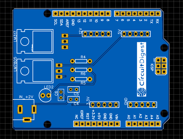
You can download the Gerber file from this link and send it to the PCBGOGO manufacturer online or you can change the board layout according to your custom design and application.
Ordering the PCB from PCBGoGo
Now when the complete design is ready it is time to get them fabricated. To get the PCB done is quite easy, simply follow the steps below
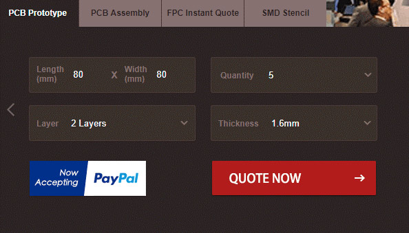
Step 1: Get into www.pcbgogo.com, sign up if this is your first time. Then, in the PCB Prototype tab enter the dimensions of your PCB, the number of layers and the number of PCB you require. Assuming the PCB is 80cm×80cm you can set the dimensions as shown below.
Step 2: Proceed by clicking on the Quote Now button. You will be taken to a page where to set few additional parameters if required like the material used track spacing etc. But mostly the default values will work fine. The only thing that we have to consider here is the price and time. As you can see the Build Time is only 2-3 days and it just costs only $5 for our PSB. You can then select a preferred shipping method based on your requirement.
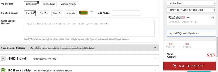
Step 3: The final step is to upload the Gerber file and proceed with the payment. To make sure the process is smooth PCBGOGO verifies if your Gerber file is valid before proceeding with the payment. This way you can sure that your PCB is fabrication friendly and will reach you as committed.
Assembling the PCB
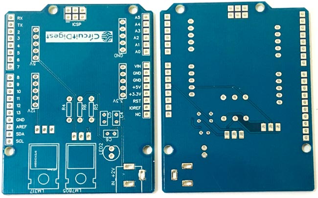
After the board was ordered, it reached me after some days though courier in a neatly labelled well-packed box and like always the quality of the PCB was awesome.
Get the soldering kit and start placing all the components in the right pads of the PCB Board. The soldering is easy to finish as there is not much components used in this project.
When the soldering is finished your board should look like below.
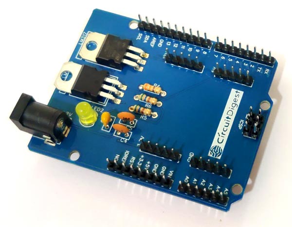
In this Power Shield the burg pins used is of male to male 20 mm connectors. You can use Male to Female Burg pins depending upon the availability. The 20mm burg pins are suitable for Arduino Shield and fits well for on Arduino UNO.
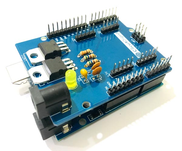
Testing the Power Supply Arduino Shield
It is really easy to test the Arduino shield. Just place the shield on to the Arduino UNO and give it a 12V supply from the input barrel jack. The shield can take input voltage of maximum up to 34V without damaging the components.
You can check all the output voltage i.e. 3.3V, 5V and 12V using a digital multimeter. If all went good including designing and soldering of the components then you will be able to note down the exact output voltage at the output pins.


A detailed video on how to design and order the PCB for the shield is given below.
This finishes the complete tutorial on making an Arduino Uno Power Supply Shield. If you face any difficulties, feel free to comment below or reach to our forum for more help.

Hi Abhiemanyu, Thanks for sharing this great article!
I would like to make changes to the board layout as you suggested, but EasyEDA PCB Designer doesn't seem to support importing Gerber files. I've tried other design applications too.
Would you be able to share the designs in an importable format please?
Many thanks!