
In this DIY project we make a 3-Channel Arduino Relay Shield Circuit for relay based applications. We designed an isolated PCB for 3 relays. By using this Arduino Relay Shield, we can operate 3 AC appliances at a time. We have put a two pin screw terminal blocks (Neutral, NO) for connecting appliances. Here we have provided PCB layout, circuit diagram, and Gerber files so that you can build or directly order this Relay Driver Module.
Previously we have built 4-channel Relay Driver Module, but this time we are building this relay module as Arduino Shield, so that you just have to fix it over Arduino and it will be ready to use. Relays are useful for triggering home AC appliances with low signal and they are used in Home Automation Systems.
Components Required:
- SPDT relay 12v -3
- 817 Optocoupler -3
- Transistor BC547 -3
- SMD LEDs -4
- PCB (ordered from JLCPCB) -1
- Terminal Block 2 pin -4
- 1N4007 Diode -3
- 1k Resistor -7
- Burg sticks male -1
- Jumper – 1
- Push Button
- Power supply
- Arduino for demonstration
- Connecting wire
- AC appliances
Arduino Relay Driver Shield Circuit Diagram:
In this 3-Channel Relay Driver Circuit, we have used an optocoupler to trigger the NPN transistor which further drives the relay. And optocoupler will be triggered by the active LOW signal. Here we have used a 12v 10Amp relay in this PCB board, you can also use 5v relays.

Working and Demonstration:
For demonstrating this Arduino Relay Driver Shield, we have used an Arduino Uno board for controlling relays. We have connected all 3 relays with Arduino at 7, 9, and 12 pins (RLY1, RLY2, and RLY3). We have used a 12v adapter for powering the circuit. Then we have connected 220VAC bulbs at the terminal block of the PCB board and AC supply is also applied to the board. Check the Demonstration Video at the end of this project.
Complete Arduino code is given at the end of this project, code is simple and easily understandable. If you want to learn more about Relay and its interfacing with Arduino then follow this link.
You just have to fix the Arduino shield over Arduino and control 3 Appliances using this shield. You can use the given code (in the end) or use your own code for controlling the AC appliaces.
Circuit and PCB Design using EasyEDA:
To design this Arduino Relay Shield, we have chosen the online EDA tool called EasyEDA. I have previously used EasyEDA many times and found it very convenient to use since it has a good collection of footprints and it is open-source. After designing the PCB, we can order the PCB samples by their low cost PCB fabrication services. They also offer component sourcing service where they have a large stock of electronic components and users can order their required components along with the PCB order.
While designing your circuits and PCBs, you can also make your circuit and PCB designs public so that other users can copy or edit them and can take benefit from your work, we have also made our whole Circuit and PCB layouts public for this circuit, check the below link:
https://easyeda.com/circuitdigest/relayshield
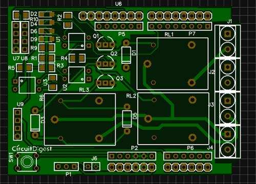
You can view any Layer (Top, Bottom, Topsilk, bottomsilk etc) of the PCB by selecting the layer form the ‘Layers’ Window. You can also view the PCB, how it will look after fabrication using the Photo View button in EasyEDA:
Calculating and Ordering Samples online:
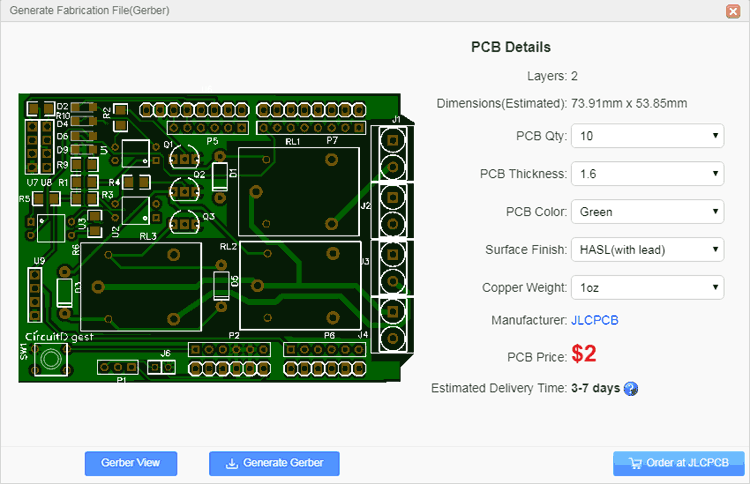
After completing the design of this Arduino Relay Shield, you can order the PCB through JLCPCB.com. To order the PCB from JLCPCB, you need Gerber File. To download Gerber files of your PCB just click the Fabrication Output button in EasyEDA editor page, then download from the EasyEDA PCB order page.
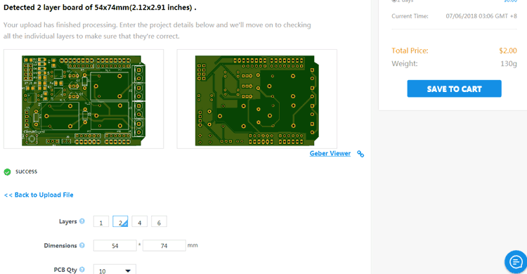
Now go to JLCPCB.com and click on Quote Now or Buy Now button, then you can select the number of PCBs you want to order, how many copper layers you need, the PCB thickness, copper weight, and even the PCB color, like the snapshot shown below:

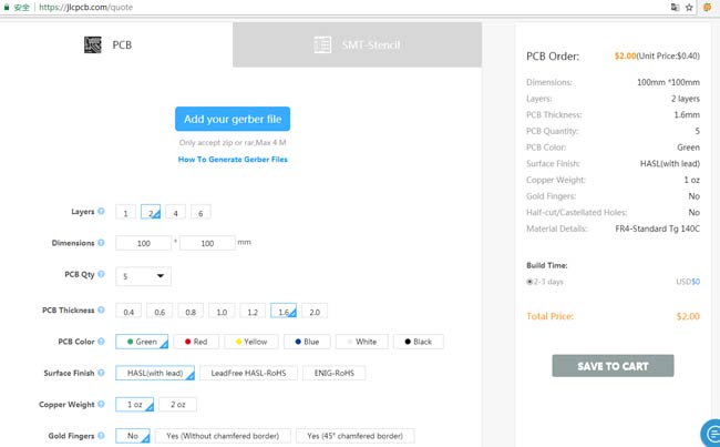
After you have selected all of the options, click “Save to Cart” and then you will be taken to the page where you can upload your Gerber File which we have downloaded from EasyEDA. Upload your Gerber file and click “Save to Cart”. And finally click on Checkout Securely to complete your order, then you will get your PCBs a few days later. They are fabricating the PCB at very low rate which is $2. Their build time is also very less which is 48 hours with DHL delivery of 3-5 days, basically you will get your PCBs within a week of ordering.
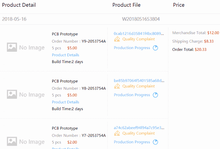
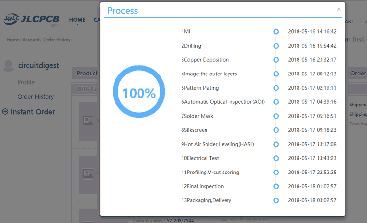
After ordering the PCB, you can check the Production Progress of your PCB with date and time. You check it by going on Account page and click on "Production Progress" link under the PCB like, shown in below image.
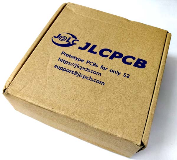
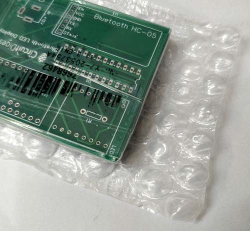
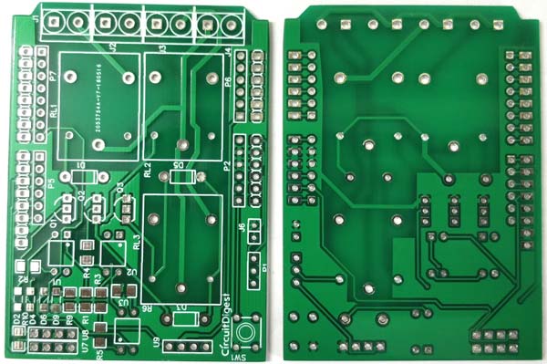
After few days of ordering PCB’s I got the PCB samples in nice packaging as shown in below pictures.
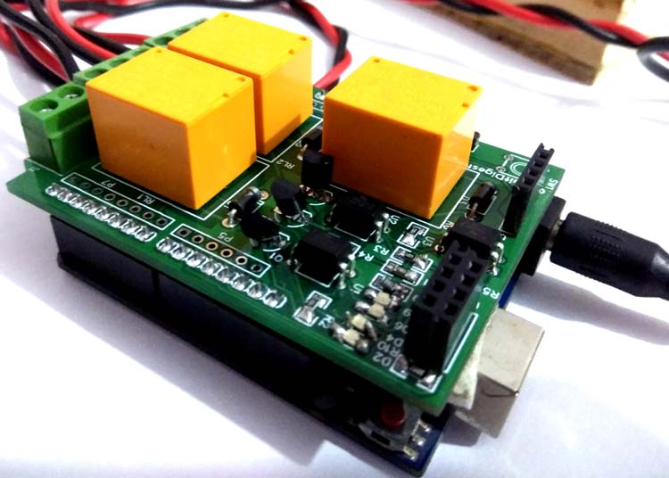
After getting these pieces I have mounted all the required components over the PCB connected it with Arduino for demonstration.
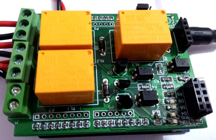
So our Arduino Relay Shield is ready, and you can directly use it with Arduino to control three AC appliances. You just have to place this Arduino shield over Arduino and upload the below given code. You can adjust the code according to you.
Also check the Demonstration Video given below.
Complete Project Code
#define RLY1 7

#define RLY2 9

#define RLY3 12
void setup()

{

  pinMode(RLY1, OUTPUT);

  pinMode(RLY2, OUTPUT);

  pinMode(RLY3, OUTPUT);

  digitalWrite(RLY1, LOW);

  digitalWrite(RLY2, LOW);

  digitalWrite(RLY3, LOW);

}
void loop()

{

   digitalWrite(RLY1, HIGH);

   digitalWrite(RLY2, HIGH);

   digitalWrite(RLY3, LOW);

   delay(1000);
      digitalWrite(RLY1, HIGH);

   digitalWrite(RLY2, LOW);

   digitalWrite(RLY3, HIGH);

   delay(1000);
    digitalWrite(RLY1, LOW);

   digitalWrite(RLY2, HIGH);

   digitalWrite(RLY3, HIGH);

   delay(1000);

}

Good knowledge in electronics projects . How it find for making devices