

A potentiometer is a mechanical device using which one can set the resistance according to the desired value, thus changing the current passing through it. There exist many applications for a potentiometer, but mostly, a potentiometer is used as a volume controller for audio amplifiers. The digital volume control circuit is an electronic circuit that accurately adjusts audio signal performance levels with integrated circuits as opposed to mechanical potentiometers. By utilising the PT2258 volume controller IC, extremely accurate digital control can be obtained with an attenuation range of 0 -79dB, meaning it should significantly outperform audio amplifier volume control circuits. This project illustrates how to build a digital volume control circuit using Arduino, which is far better than any of the traditional analogue volume control circuits.
A potentiometer does not control the gain of the signal, but it forms a voltage divider, and that is why the input signal gets attenuated. So in this project, I am going to show you how to build your Digital Volume Controller with the IC PT2258 and interface it with an Arduino to control the volume of an amplifier circuit. You can also check various Audio-related circuits here, including a VU meter, tone control circuit, etc. The digital volume control board design presented here supports 6-channel operation, perfect for home theatre systems and professional audio applications.
Table of Contents
- Digital Volume Control vs. Mechanical Potentiometers
- Understanding the PT2258 IC
- └ Technical Specifications
- How the PT2258 Digital Volume Controller Works
- └ Initialisation Requirements for Stable Operation
- Circuit Diagram with PT2258 and Arduino
- Components Required
- Arduino Code
- └ Channel Mapping Reference
- GitHub Repository
- Testing
- Further Enhancement
Digital Volume Control vs. Mechanical Potentiometers
| Feature | Digital Volume Control Circuit | Mechanical Potentiometer |
| Precision | 1dB step accuracy, digital repeatability | Variable, depends on physical position |
| Channel Separation | >90dB (PT2258 IC specification) | Poor matching between channels |
| Signal-to-Noise Ratio | >100dB (PT2258 specification) | 60-80dB typical |
| Lifespan | No mechanical wear, virtually unlimited | Limited by mechanical wear (10,000-50,000 cycles) |
| Remote Control | Easy I2C integration with microcontrollers | Requires motorized solution (complex) |
| Noise | Low noise, no scratching sounds | Contact noise, crackling over time |
Understanding the PT2258 IC for Volume Control Applications

As I have mentioned earlier, the PT2258 is an IC made to use as a 6-Channel Electronic Volume Controller. This IC uses CMOS technology specially designed for multi-channel audio-video applications. This audio amplifier volume control circuit component provides an I2C control interface, making it perfect for integration with Arduino, Raspberry Pi, and other microcontrollers in professional audio systems.
This IC provides an I2C Control Interface with an attenuation range of 0 to -79dB at 1dB/step and comes in a 20-pin DIP or SOP package.
PT2258 Volume Controller Technical Specifications
- Control Interface: I2C bus (SCL and SDA lines) with the highest clock frequency of 100KHz
- Attenuation Range: 0dB to -79dB in accurate 1dB steps (80 discrete volume levels)
- Channels: 6 independent input/output channels for a 5.1 surround sound system
- Channel Separation: >90dB or greater at 1KHz for professional audio quality
- Signal-to-Noise Ratio: 100+dB for clear, clean notes and reproduction
- Operating Voltage: 5V to 9V DC for all standard audio equipment power supplies
- I2C Addressing: 4 selectable addresses derived from CODE1 and CODE2 pins when daisy-chaining one or more volume controllers together
- Package Options: 20-pin DIP and SOP package options, PCB design requirements
- Total harmonic distortion: THD <0.01% at 1KHz
- Input Impedance: 27KΩ typical- sufficient for almost all audio source outputs.
How the PT2258 Digital Volume Controller Works
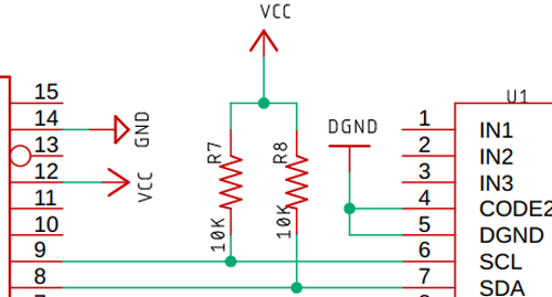
This PT2258 volume controller operates through an IC that transmits and receives data from the microcontroller via SCL and SDA lines. The SDA and SCL make up the bus interface. These lines must be pulled high by two 4.7K resistors in order to ensure stable operation.
I2C Communication Protocol for Volume Control
Before we go to the actual hardware operation, here is the detailed functional description of the IC. If you don't want to know all this, you can skip this part because all the functional part is managed by the Arduino library.
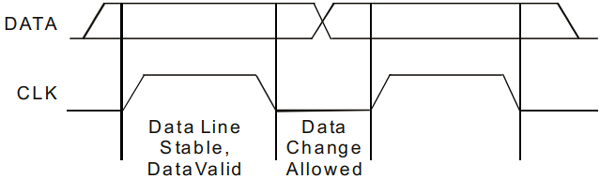
Data Validation Process:
- The data on the SDA line is considered stable when the SCL signal is HIGH.
- The HIGH and LOW states of the SDA line change only when the SCL is LOW.
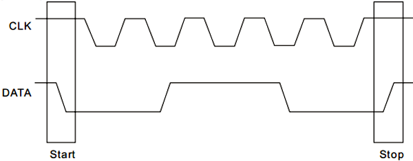
Start and Stop Conditions in I2C Communication
A Start Condition is activated when
- The SCL is set to HIGH and
- SDA shifts from HIGH to LOW State. This signals the beginning of communication with the digital volume control circuit.
The Stop Condition is activated when
- SCL is set to HIGH and
- SDA shifts from LOW to HIGH State
Note! Understanding these timing requirements is crucial for debugging digital volume control circuit diagram implementations and troubleshooting communication issues.
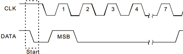
Data Format
Every byte transmitted to the SDA Line consists of 8 bits, which form a byte. Each byte must be followed by an Acknowledge Bit.
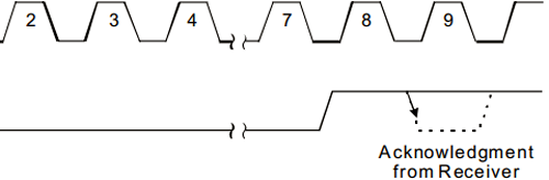
Acknowledgment Mechanism
Acknowledgement ensures stable and proper operation. During the Acknowledge Clock Pulse, the microcontroller pulls the SDA pin HIGH. At this exact moment, the peripheral device (audio processor) pulls down (LOW) the SDA line. During the ninth clock pulse, the PT2258 volume controller (slave device) pulls the SDA line LOW to acknowledge data receipt.
The peripheral device (PT2258) is now addressed & it has to generate an acknowledge after receiving a byte; otherwise, the SDA line will remain at a High level during the ninth (9th) Clock Pulse. If this happens, the master transmitter will generate STOP Information in order to abort the transfer.
That clears the need to be in place for a valid data transfer.
PT2258 I2C Address Selection Configuration
The PT2258 IC address of this IC depends on the state of CODE1 (Pin No.17) and CODE2 (Pin No.4). This enables daisy-chaining multiple digital volume control boards for complex multi-zone audio systems.
CODE1 (PIN No. 17) | CODE2 (PIN No. 4) | HEX ADDRESS |
0 | 0 | 0X80 |
0 | 1 | 0X84 |
1 | 0 | 0X88 |
1 | 1 | 0X8C |
Configuration Tip: For single-board applications, grounding both CODE1 and CODE2 pins (address 0x80) is the standard approach in most audio amplifier volume control circuit designs.
Logic High = 1
Logic Low = 0
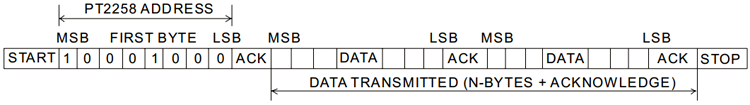
I2C Interface Protocol Sequence
The interface protocol consists of the following:
- A Start bit
- A Chip Address Byte
- ACK=Acknowledge bit
- A Data byte
- A Stop bit
Initialisation Requirements for Stable Operation
A little Housekeeping
After the IC is powered on, it needs to wait at least 200ms before transmitting the first data bit; otherwise, the data transfer may fail.
After the delay, the first thing to do is to clear the register by sending “0XC0” via the I2C line. This ensures proper operation.

The above step clears the entire register. Now, we need to set a value to the register; otherwise, the register stores a garbage value, and we get a freckled output.
To ensure proper volume adjustments, it is necessary to send a multiple of 10dB followed by a 1dB code to the attenuator in sequence; otherwise, the IC can behave abnormally. The diagram below clarifies it more.
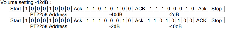
After powering on the digital volume control circuit, wait a minimum of 200ms before transmitting any I2C commands.
Both the above methods will work properly.
To ensure proper operation, make sure that the I2C data transfer speed never exceeds 100KHz.
That's how you can transmit a byte to the IC and attenuate the input signal. The above section is to learn how the IC functions, but as I have said earlier, we are going to use an Arduino library to communicate with the IC, which manages all the hard code, and we just need to make some function calls.
All the above information is taken from the PT2258 datasheet. Please refer to it for further information.
Digital Volume Control Circuit Diagram with PT2258 and Arduino

The above image shows the test schematic of the PT2258 based Volume Control Circuit. It’s taken from the datasheet and modified according to need. This digital volume control circuit diagram shows the complete schematic for building an Arduino-controlled audio amplifier volume control circuit.
For the demonstration, the circuit is constructed on a solderless breadboard with the help of the schematic shown above.
Note! All the components are placed as closely as possible to reduce parasitic capacitance, inductance and resistance.
Components Required for Digital Volume Control Circuit
- PT2258 IC – 1
- Arduino Nano Controller – 1
- Generic Breadboard – 1
- Screw Terminal 5mm x 3 – 1
- Push Button – 1
- 4.7K Resistor, 5% - 2
- 150K Resistor, 5% - 4
- 10k Resistor, 5% - 2
- 10uF Capacitor – 6
- 0.1uF Capacitor – 1
- Jumper Wires - 10
Arduino Code for Digital Volume Control Circuit Using PT2258
For simplicity, I am going to use a PT2258 library from GitHub, which is made by sunrutcon.
This is a very well-written library, which is why I have decided to use it, but since it is very old, it’s a little buggy, and we need to fix it before we can use it.
First, download & extract the library from the GitHub repository.
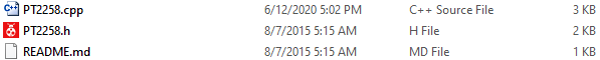
You will get the above two files after extraction.
#include <arduino.h>
#include <wire.h>
#include <PT2258.h>
Next, open the PT2258.cpp file with your favourite Text Editor. I am using Notepad++.
You can see that the “w” of the wire library is in small letters, which is incompatible with the latest Arduino versions, & you need to replace it with a capital “W”, that's it.
Complete code for the PT2258 Volume Controller can be found at the end of this section. Here, important parts of the program are explained.
We start the code by including all the required library files. The Wire library is used to communicate between the Arduino and the PT2258. The PT2258 library contains all the critical I2C timing information and acknowledgements. The ezButton library is used to interface with the push-buttons.
Instead of using below code images below, copy all the code instances from the code file and format them Formatted like we used to do in other projects
#include <PT2258.h>
#include <ezButton.h>
#include <Wire.h>
Next, make the objects for the two buttons and the PT2258 library itself.
PT2258 pt2258;
ezButton button_1(2);
ezButton button_2(4);
Next, define the volume level. This is the default volume level that this IC will start with.
Int volume = 40;Next, initiate the UART, and set the clock frequency for the I2C bus.
Serial.begin(9600);
Wire.setClock(100000);
It’s very important to set the I2C clock; otherwise, the IC will not work because the maximum clock frequency supported by this IC is 100KHz.
Next, we do a little housekeeping with an if-else statement in order to ensure the IC is communicating properly with the I2C bus.
If (!pt2258.init())
 Serial.printIn(“PT2258 Successfully Initiated”);
Else
 Serial.printIn(“Failed to Initiate PT2258”);
Next, we set the debounce delay for the pushbuttons.
Button_1.setDebounceTime(50);
Button_2.setDebounceTime(50);
Finally, initiate the PT2258 IC by setting it up with the default channel volume and PIN.
/* Iniciating PT with default volume and Pin*/
Pt2258.setChannelVolume(volume,4);
Pt2258.setChannelVolume(volume,5);
This marks the end of the Void Setup() section.
In the Loop section, we need to call the loop function from the button class; it's a library norm.
Button_1.loop(); //Library norms
Button_2.loop(); //Library norms
The below if section is to decrease the volume.
/* if button 1 is pressed if condition is true */
If (button_1.ispressed())
{
   Volume++; // Incrementing the volume counter.
   // This if statement ensures the volume does not goes above 79
   If (volume >= 79)
   {
   Volume = 79;
   }
   Serial.print(“volume: “); // printing the volume level
   Serial.printIn(volume);
   /* set the volume for channel 4
   Which is in PIN 9 of the PT2558 IC
  */
  Pt2558.setChannelVolume(volume,4);
  /*set the volume for channel 5
  Which is the PIN 10 of the PT2558 IC
  */
  Pt2558.setChannelVolume(volume,5);
}
The below if section below is to increase the volume.
// The same happens for the button 2
If (button_2.isPressed())
{
Volume--;
// this if statement ensures the volume level does not go below zero.
If (volume <= 0)
Volume = 0;
Serial.print(“volume: “);
Serial.printIn(volume);
Pt2258.setChannelVolume(volume,4);
Pt2558.setChannelVolume(volume,5);
}
Channel Mapping Reference
| Software Channel | PT2258 Pin | Typical Application |
| Channel 0 | Pin 3 (FL) | Front Left (5.1 systems) |
| Channel 1 | Pin 5 (FR) | Front Right (5.1 systems) |
| Channel 2 | Pin 7 (CEN) | Center Channel |
| Channel 3 | Pin 8 (SUB) | Subwoofer |
| Channel 4 | Pin 9 (RL) | Rear Left / Stereo Left |
| Channel 5 | Pin 10 (RR) | Rear Right / Stereo Right |
Technical Summary and GitHub Repository
A brief overview of the project’s purpose and key technologies. The GitHub repository hosts the source code, documentation, and version control. It ensures collaboration, transparency, and easy project maintenance.


Testing the Digital Audio Volume Control Circuit
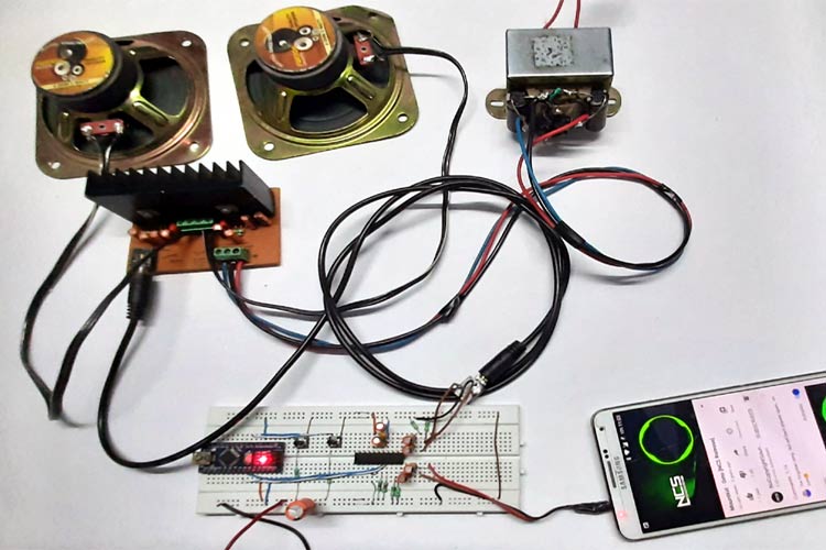
Test Setup Requirements
To test the circuit, the following apparatus was used
- A transformer which has a 13-0-13 Tap
- 2 4Ω 20W speaker as a load.
- Audio source (Phone)
In a previous article, I showed you how to make a Simple 2x32-watt audio Amplifier with the TDA2050 IC. I am going to use that for this demonstration also.
I have disassembled the mechanical potentiometer and shorted two leads with two small jumper cables.
Now, with the help of two push-buttons, the volume of the amplifier can be controlled.
Testing Results: The digital volume control circuit provides precise 1dB step control with no mechanical noise, scratching, or channel imbalance across the entire volume range.
Further Enhancement Options for Professional Applications
The circuit can be further modified to improve its performance. Improvements like the circuit can be made to a PCB to further eliminate the noise generated by the digital section of the IC. We can also add a filter to reject high-frequency noises. Also, check out other Audio Amplifier circuits and other Audio-related projects.
PCB Design for Production
Transitioning from breadboard to a professional digital volume control board PCB offers significant advantages:
∗ Ground Plane: Solid ground plane reduces electromagnetic interference (EMI) and improves signal-to-noise ratio by 10-15dB
∗ Shorter Traces: Minimised trace length reduces parasitic capacitance and inductance, preserving high-frequency audio content
∗ SMD Components: Surface-mount components further reduce trace length and improve high-frequency performance
∗ Shielding: Add a copper pour around sensitive analog sections to prevent digital noise coupling
Frequently Asked Questions About the Digital Volume Control Circuit
⇥ 1. What is a digital volume control circuit, and how does it differ from analog potentiometers?
A digital volume control circuit using integrated circuits (such as the PT2258) electronically controls audio levels using I2C commands; it has the advantage of giving accurate 1dB steps, no mechanical wear, channel separation in excess of 90dB, and remote control. Analog potentiometers mechanically create voltage dividers and are subject to contact noise and channel imbalance, while having limited life expectancy (10,000 to 50,000 cycles) and an inability to interface to microcontrollers.
⇥ 2. Why use the PT2258 IC instead of other volume controller ICs?
The PT2258 volume controller provides great value with 6 independent channels for 5.1 surround systems, 100dB+ signal-to-noise ratio, simple I2C interface compatible with Arduino and Raspberry Pi, 0 to -79dB attenuation range in 1dB steps, and a very inexpensive price of less than $3. Other comparable ICs, such as PGA2310 or CS3310, have much greater performance but cost 10 to 15 times more, so the PT2258 is ideal for DIY audio projects.
⇥ 3. Can I use a PT2258 digital volume control circuit with any audio amplifier?
Yes, you may use a PT2258 digital volume control circuit with any audio amplifier that accepts line-level inputs, typically in the range of 0.5 to 2V RMS. These amplifiers can include, but are not limited to, a TDA2050, LM3886, TDA7293, class D amplifiers, and tube amps with proper impedance matching. The PT2258 has a 27KΩ input impedance, and its output impedance is low, so it will not load down the signal source devices or cause downstream amplifiers any impedance mismatches.
⇥ 4. What is the maximum I2C clock frequency for PT2258, and why does it matter?
The PT2258 IC maximum I2C clock frequency supported is 100KHz. Any frequency above that may cause communication failures, missed acknowledgements to the speaker commands, and/or erratic volume control. The default Wire library for Arduino uses a 100KHz rate, but some microcontrollers use 400KHz (Fast Mode) as the default rate, which should be changed to 100,000 with a Wire.setClock(100000) command. Generally, slower clock speeds of 10-50KHz work reliably but may slightly increase the time to transmit commands. This difference is seldom noticed with audio applications.
⇥ 5. What is the volume step resolution for the PT2258, and is it within the range of hearing?
The PT2258 volume controller has 80 discrete volume levels at 1 dB (-79dB to 0dB). For human hearing, 1dB is approximately the step size of minimum detection in a controlled environment, while listeners can consistently hear changes of 2-3dB. Thus, the 1dB resolution provides for smooth and professional volume change, without audible "stepping" artefacts. For reference, normal analog potentiometers could provide infinite resolution, but tracking errors greater than 2-3dB could happen between stereo channels.
⇥ 6. Can I control all 6 channels of the PT2258 independently for surround sound systems?
Yes, the PT2258 does allow you to control the volume of all 6 channels independently via software commands: pt2258.setChannelVolume (attenuation, channel). Channels numbered 0-5 correspond to pins FL, FR, CEN, SUB, RL, RR. You are able, therefore, to create custom volume profiles, such as low attenuation of the subwoofer for bass boost, some attenuation of the centre channel for clarity of dialogue, or asymmetric stereo balance. In multi-channel control, it means that different I2C commands would be specified by channel.
⇥ 7. What causes digital volume control circuits to have noise, and how do I fix them?
Noise sources can include: Poor filtering of the power supply—adding 100µF + 0.1µF capacitors at the PT2258 VCC pin will clean this up; digital noise caused by the Arduino coupling into the analog paths—using separate ground planes or star ground will mitigate this source. Long input/output wires create antennas—the I/O wires should be kept to under 6 inches or use shielded cable; Parasitic capacitance in breadboards—move to a PCB with a good ground plane. If you do all of the above, it appears the proper layout can get the noise floor down to 15-20dB lower, and the SNR specified in the datasheets for the PT2258 is >100dB.
Conclusion
This digital volume control circuit using Arduino and PT2258 IC, serves as an excellent replacement to use mechanical potentiometers to control the volume in an audio amplifier volume control. The volume is attenuated by 1dB steps, providing a 100dB+ signal-to-noise ratio with 6 channels, and there are no mechanical parts to wear out. The PT2258 volume controller allows DIY audio systems to achieve a true professional level of design at a reasonable cost.
This digital volume control circuit diagram can be used when designing stereo amplifiers, 5.1 home theatre systems, or multi-zone audio distribution systems this digital volume control circuit diagram.
This tutorial was created by the Circuit Digest engineering team. Our experts focus on creating practical, hands-on tutorials that help makers and engineers master Raspberry Pi projects, Arduino projects, Microcontroller projects and IoT development projects.
I hope you liked this article and learned something new from it. For questions, detailed discussions, or sharing your own digital volume control board implementations, you can ask in the comments below or use our CircuitDigest forum.
Innovative Audio and Media Control Projects
A collection of creative projects integrating audio, media, and control systems using Raspberry Pi, Arduino, and simple electronic circuits.These projects demonstrate gesture and voice control applications along with fundamental audio circuit design.

Voice Controlled FM Radio using Arduino and Google Assistant
So, to revive the old glory of the FM radio a bit, in this project, I am going to building a voice-controlled FM radio using Google Assistance and the popular RDA5870M Superheterodyne Receiver IC.

Simple Audio Tone Control Circuit
To control the output means we can control the Volume, Treble and Bass of the Audio output. So, to achieve this aim we have to control the output frequency.

In this tutorial, we are going to use the MediaPipe Python library to detect our hand gestures and control the Raspberry Pi media player using that.
Complete Project Code
#include <PT2258.h>
#include <ezButton.h>
#include <Wire.h>
PT2258 pt2258; // PT2258 Object
ezButton button_1(2); //Button_1 Object
ezButton button_2(4); //Button_2 Object
int volume = 40; // Default volume / Starting Volume
void setup() {
  Serial.begin(9600); //UART begin
  Wire.setClock(100000); // setting the I2C clock to 100KHz
  /* checking if the MCU can talk with the PT or not*/
  if (!pt2258.init())
    Serial.println("PT2258 Successfully Initiated");
  else
    Serial.println("Failed to Initiate PT2258");
  /* Setting up button debounce delay*/
  button_1.setDebounceTime(50);
  button_2.setDebounceTime(50);
  /* Initiating PT with default volume and Pin*/
  pt2258.setChannelVolume(volume, 4);
  pt2258.setChannelVolume(volume, 5);
}
void loop() {
  button_1.loop(); //Library norms
  button_2.loop(); //Library norms
  /* If button 1 is pressed if condition is true*/
  if (button_1.isPressed())
  {
    volume++; // Incrementing the volume counter.
    // this if statement ensures the volume does not goes above 79
    if (volume >= 79)
    {
      volume = 79;
    }
    Serial.print("volume: "); // Printing the volume level
    Serial.println(volume);
    /*Set the volume for channel 4
      Which is in PIN 9 of the PT2258 IC
    */
    pt2258.setChannelVolume(volume, 4);
    /*Set the volume for channel 5
       Which is the Pin 10 of the PT2258 IC
    */
    pt2258.setChannelVolume(volume, 5);
  }
  //The same happens for the button 2
  if (button_2.isPressed())
  {
    volume--;
    // this if statement ensures the volume level doesn't go below zero.
    if (volume <= 0)
      volume = 0;
    Serial.print("volume: ");
    Serial.println(volume);
    pt2258.setChannelVolume(volume, 4);
    pt2258.setChannelVolume(volume, 5);
  }
}Comments
03452365387
i need a pt2258
need a pt 2258

Hi
i have tried all the steps and observed that nothing is working
in case it is failed to initialize, the message should print
i have noticed one thing, i have checked the address of it using I2c scanner, it shows address is "0x44" but in IC pin 17 is Vcc (means 1) and Pin 4 is ground (means 0) so the address should be "0x88" right?
Please help me to resolve this