 Vedhathiri
Author

With the increasing demand for automation and remote operation, controlling electrical devices without the need for physical access has become an important area of development in modern engineering. Automation helps reduce manual effort, improves operational efficiency, and enhances safety, especially in environments where human presence is difficult. As a result, remote control technologies are being widely adopted across various sectors. Among the many components used in these systems, DC motors play a crucial role due to their simple construction, reliability, and ease of control.
They are commonly used in systems such as conveyor belts, irrigation pumps, automated doors, and household appliances, where accurate control over speed and direction is essential for proper operation and performance. Traditional motor control methods generally depend on manual switches or wired control systems. While effective, these approaches limit flexibility and require the operator to be physically present near the control unit. This can be inconvenient, time-consuming, and impractical in remote or large-scale applications, highlighting the need for more flexible and wireless control solutions. To overcome this, we made a project that focuses on controlling the forward and reverse direction as well as the speed of a DC motor using SMS-based commands. Instead of using physical switches or direct wiring, the motor can be operated remotely by sending predefined text messages from a mobile phone.
In this project, Arduino DC motor control using GSM, you will learn how to create an entire SMS-based system to control your motor using an Arduino Uno, SIM800L GSM module, L298N H-Bridge Motor Driver, and bidirectional logic level conversion circuit from the ground up. This tutorial will provide you with the complete schematic diagram for controlling the speed of the DC motor speed control using GSM, wiring information for all of the pins, a step-by-step explanation of how the project works, and complete Arduino DC motor speed control code for controlling the speed, with an overview of each part of the code, along with troubleshooting guidance. Each SMS command represents a specific motor action, such as changing the direction of rotation or adjusting the speed level. Let's dive in and see how it's made. To explore more hands-on ideas and implementations, take a look at our electronics projects.
Quick Overview - What This GSM Motor Control System Does
- Receives SMS commands (FWD, REV, STOP + speed value) via SIM800L GSM module
- Arduino Uno parses each command and determines the motor action required
- L298N motor driver controls direction via IN1/IN2 logic levels and speed via PWM on ENA
- Applicable to agriculture, industrial automation, home automation, and security systems
Table of Contents
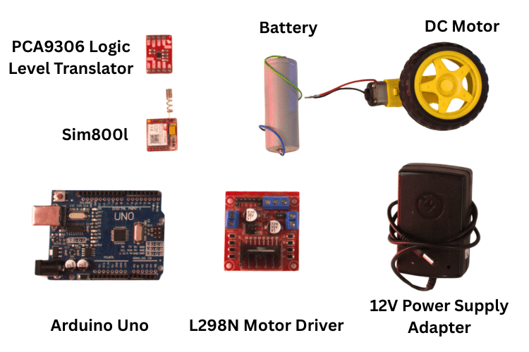
Components Required for DC Motor Control Using Arduino
Below is the complete component list for this DC motor speed control using GSM Arduino project.
| S.no | Component | Quantity | Purpose |
| 1. | Arduino Uno | 1 | Acts as the main controller of the system. It processes SMS commands and generates control signals for motor speed and direction. |
| 2. | Dc Motor | 1 | Converts electrical energy into mechanical motion. Its speed and direction are controlled according to the received commands. |
| 3. | USB Cable | 1 | Used to upload the program to the Arduino Uno. It also provides power and serial communication during testing. |
| 4. | Level Shifter | 1 | Matches voltage levels between the Arduino and GSM module. It ensures safe and reliable serial communication. |
| 5. | L298N Motor Driver | 1 | Drives the DC motor by supplying sufficient current. It allows control of motor direction and speed. |
| 6. | Sim800L | 1 | Receives SMS commands from the user’s mobile phone. Sends the command data to the Arduino for processing. |
| 7. | Breadboard | 1 | Provides a temporary platform for circuit connections. Allows easy modification without soldering. |
| 8. | External Batteries/Power Supply Adapter | 1 | Supplies required power to the motor and GSM module. Ensures stable operation of the system |
| 9. | Jumper Wires | - | Used to connect various components electrically. Enables signal and power transfer between modules. |
| 10. | Arduino IDE | - | Used to write and compile the Arduino program. Uploads the code to the Arduino Uno. |
Circuit Diagram of GSM-Based DC Motor Speed Control
The DC motor speed control using GSM uses an Arduino Uno as the main controller, a SIM800 GSM module to receive SMS commands, a logic level translator for safe voltage conversion, and an L298N motor driver to control the DC motor. An external power supply is used to provide sufficient power for the motor and GSM module. The Arduino processes the SMS commands received through the GSM module and controls the motor accordingly. Since the Arduino and GSM module operate at different logic voltage levels, a level shifter is used to ensure safe serial communication between them.

The L298N motor driver controls the direction and speed of the DC motor, with speed control achieved using PWM signals from the Arduino. A common ground is shared among all components for reliable operation, enabling efficient remote motor control using SMS through the GSM network.
Key Design Decisions in This Circuit
∗ Level-Shifting Device Required: The SIM800L UART interface is at a lower logic rail than that of the connecting device; thus, applying a 5V supply directly to the SIM800L RX pin would cause excessive voltage and likely damage the module. A bi-directional level shifter will facilitate safe exchange of signals between the 5V supply (High Voltage) and the 3.3V signal (Low Voltage).
∗ Separate Power Rail Systems: Both the SIM800L and DC motor are supplied by an independent source, with the external supply connected to the Arduino by a common ground, thus preventing the high Ampere current spikes from adversely affecting the Arduino power source when powered by the GSM module.
∗ Pulse Width Modulation Signal (PWM) on D9: Pin D9 of Uno is an analog PWM output; this may be used in conjunction with the L298N ENA input to regulate the DC motor speed via duty cycle (0-255) based on the Pulse Width Modulation.
∗ Common Grounds: Every device in the circuit must connect to the same reference electrical ground (Arduino, Level Shift, L298N, SIM800L and external Supply); without a common reference GND, the reliability of the signal will be compromised, resulting in unsafe device operations.
Pinout Table for DC Motor Control Using GSM
The pinout table defines the connections between the Arduino Uno, GSM module, DC motor, and L298N motor driver. It helps clarify any doubts regarding the connections shown in the circuit diagram.
Arduino Uno ↔ Logic Level Shifter ↔ SIM800L GSM Module
| Arduino Uno | Level Translator | GSM Module |
| 5V | HV/VREF(H) | - |
| 3.3V | LV/VREF(L) | - |
| GND | GND | GND |
| D3(TX) | HV SDA1-> LV SDA1 | RX |
| D2(RX) | HV SCL1-> LV SCL1 | TX |
Arduino Uno ↔ L298N Motor Driver
| Arduino Uno | L298N Motor Driver |
| D5 | IN1 |
| D6 | IN2 |
| D9 | ENA |
| 5V | +5V |
| GND | GND |
L298N ↔ DC Motor and External Power Supply
| Component | Connection |
| DC Motor | OUT1 & OUT2 |
| External Battery | +12V/VIN |
| External Battery | GND |
SIM800L GSM Module — Power Connections
| GSM Module Pin | Connection |
| VDD/5V | External Battery |
| GND | External Battery GND |
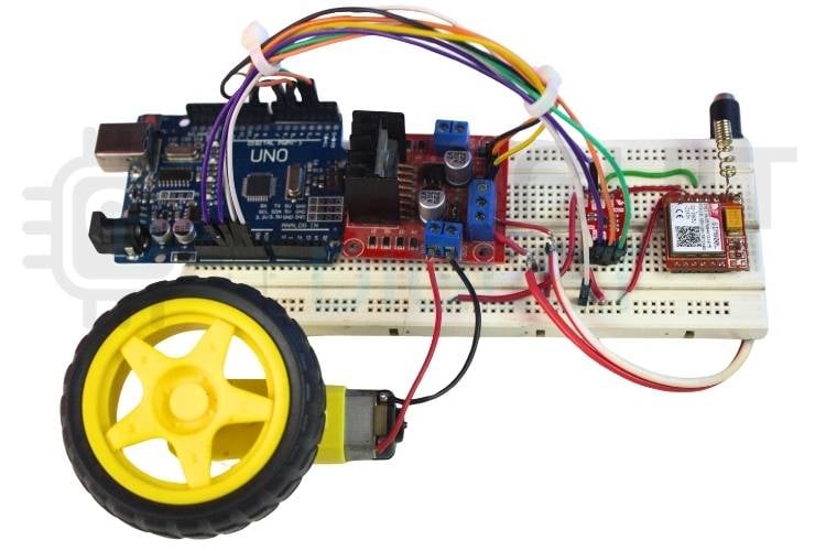
Hardware Setup for GSM-Based DC Motor Control
The hardware setup shows how all the individual components are physically assembled and interconnected in real time to form a complete working system.
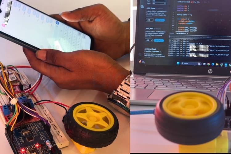
How Speed and Direction Control of a DC Motor Using GSM Works
This section explains the complete signal flow from your mobile phone to the spinning motor shaft, the core mechanism behind speed and direction control of a DC motor using GSM. When the circuit is powered ON, the Arduino Uno and the SIM800 GSM module are initialised. The GSM module registers with the available mobile network and enters an idle state, waiting to receive SMS messages. During this stage, the Arduino continuously monitors the serial communication interface to detect any incoming data from the GSM module.
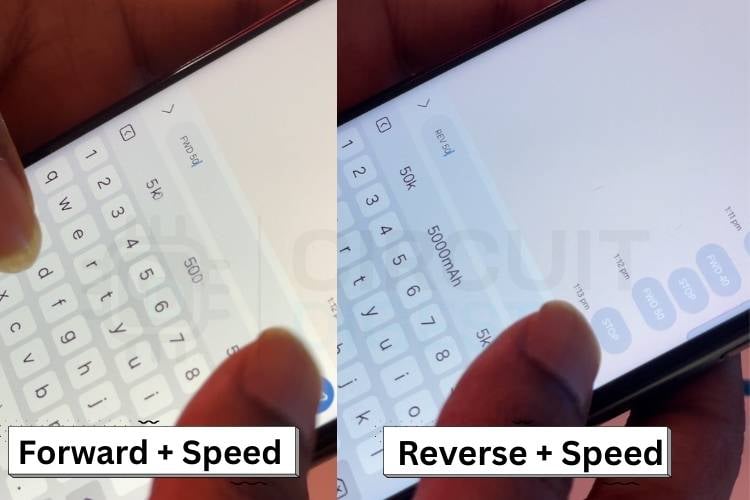
SMS Command Reference — DC Motor Control via GSM
| SMS Text | Motor Action |
| FWD[speed] | Rotate forward at the given speed |
| REV[speed] | Rotate in reverse at the given speed |
| STOP | Halt motor immediately |
The user sends a predefined SMS command from a mobile to the module. Once the SMS is received, the GSM module forwards the message content to the Arduino using serial communication. Since the Arduino and GSM module operate at different logic voltage levels, the level translator ensures safe and reliable data transfer between the two devices. The Arduino reads the received SMS and compares it with the predefined control commands stored in the program. Based on the matched command, the Arduino determines the required motor operation. If the command is related to direction control, the Arduino sets the appropriate logic levels on the input pins of the L298N motor driver to rotate the motor in either the forward or reverse direction.
For speed control, the Arduino generates a Pulse Width Modulation (PWM) signal on the enable pin of the L298N motor driver. By varying the duty cycle of the PWM signal, the speed of the DC motor is increased or decreased as required. All components share a common ground to maintain proper signal communication and stable operation. Using this setup, the DC motor can be controlled remotely for speed and direction through simple SMS commands. If you are more into making projects with the DC Motor, just look at these interesting DC Motor Control Using MATLAB and Arduino and Control DC Motor with Arduino and L293D Motor Driver IC projects.
Arduino DC Motor Speed Control Code- Full Explanation
The sections below break down every key block of the Arduino DC motor speed control code. This code implements SMS-based control of a DC motor using a GSM module and Arduino Uno. The GSM module receives text commands from the user and forwards them to the Arduino through serial communication. The Arduino processes these commands and controls the motor direction using digital pins and speed using PWM signals. AT commands configure the GSM module for real-time SMS handling. The motor driver amplifies control signals to safely drive the DC motor. Also, check our project Wireless DC Motor Speed Control using an IR Remote and a 555 Timer IC.
1. Library and SoftwareSerial Initialisation
#include <SoftwareSerial.h>
SoftwareSerial gsm(3, 2);  // RX, TX
The SoftwareSerial library is used to create a serial interface for the GSM module. Pins 3 and 2 are configured as RX and TX to communicate with the SIM800 module. This allows GSM communication without using the Arduino’s hardware serial port, keeping it free for debugging.
2. Motor Driver Pin Definitions and Setup
#define ENA 9
#define IN1 5
#define IN2 6
pinMode(ENA, OUTPUT);
pinMode(IN1, OUTPUT);
pinMode(IN2, OUTPUT);
stopMotor();
The motor driver pins are defined for speed and direction control. ENA is used for PWM-based speed control, while IN1 and IN2 decide the rotation direction. All pins are configured as outputs, and the motor is stopped initially to ensure safe startup.
3. GSM Module AT Command Initialisation
gsm.println("AT");
gsm.println("AT+CMGF=1");
gsm.println("AT+CSCS=\"GSM\"");
gsm.println("AT+CNMI=2,2,0,0,0");
These AT commands initialise the GSM module for SMS-based communication. The module is set to text mode and GSM character set. Instant SMS notification is enabled so that new messages are sent directly to the Arduino without manual reading.
4. Main Loop - Continuous Serial Reading
while (gsm.available()) {
 char c = gsm.read();
 if (c == '\n') {
   processLine(line);
   line = "";
 } else if (c != '\r') {
   line += c;
 }
}
Incoming data from the GSM module is read character by character. Each SMS message is collected line by line and passed to the processing function. Empty lines and unnecessary characters are ignored to avoid incorrect command detection.
5. Command Parsing and Motor Action
if (msg.startsWith("FWD")) {
 forward(getSpeed(msg));
}
else if (msg.startsWith("REV")) {
 reverse(getSpeed(msg));
}
else if (msg.startsWith("STOP")) {
 stopMotor();
}
The received SMS is checked for predefined commands such as FWD, REV, and STOP. Direction is controlled by setting logic levels on the motor driver inputs. Speed is extracted from the message and applied using PWM to control motor speed smoothly.
Troubleshooting the DC Motor Speed Control Using GSM Arduino
Issue 1: GSM Module Not Responding to AT Commands
If the GSM module does not respond to AT commands, the first step is to check the power supply. The SIM800 module requires a stable power source with sufficient current, especially during network registration. Ensure that the SIM card is properly inserted and active. Verify the baud rate used in the code matches the GSM module’s default baud rate. Also, confirm that TX and RX connections are correct and not reversed.
Issue 2: SMS Commands Not Being Received
If SMS messages are not received by the Arduino, check whether the GSM module is registered on the network. This can be verified using the AT+CREG? command. Ensure that SMS text mode is enabled using AT+CMGF=1. Poor network signal strength can also prevent message delivery, so the antenna connection should be checked. Restarting the GSM module after setup often resolves temporary communication issues.
Issue 3: Motor Not Rotating
If the DC motor does not rotate, inspect the connections between the motor and the L298N motor driver. Ensure that the external power supply is properly connected to the motor driver, as the Arduino cannot supply enough current. Check whether the enable pin (ENA) is receiving a PWM signal from the Arduino. Also, verify that the motor driver input pins are correctly connected to the defined Arduino pins.
Issue 4: Motor Rotates but Direction Is Incorrect
If the motor rotates in the opposite direction from what is expected, the input connections to the motor driver may be reversed. Swapping the connections of IN1 and IN2 or the motor terminals at the driver output can fix this issue. Ensure that the logic levels sent by the Arduino match the intended direction commands. Reviewing the SMS command format and matching it with the code logic is also recommended.
Issue 5: Motor Speed Not Changing
If the motor speed does not change even when different speed values are sent, check whether the ENA pin is connected to a PWM-capable Arduino pin. Verify that the speed value extracted from the SMS is within the valid PWM range (0–255). Ensure that analogWrite() is being used instead of digitalWrite() for speed control. Loose jumper connections can also cause unstable PWM output
Real-World Applications of GSM-Based DC Motor Control
Where SMS-Based DC Motor Control Is Applied
» Remote Industrial Motor Control
Used to control industrial motors from distant or hazardous locations using SMS commands. Reduces manual operation and improves safety.
» Agricultural Motor Control
Useful for remotely controlling irrigation and water pump motors in agricultural fields. Helps farmers operate motors without being physically present.
» Security and Gate Automation
Applied in automated gates, barriers, and security systems where motor direction and speed control are required. SMS control provides easy and reliable access management.
» Home Automation Systems
Can be used to control household motorized devices such as curtains, shutters, or exhaust fans. Enables simple remote operation without internet dependency.
Conclusion
This project demonstrates a practical, cost-effective approach to DC motor speed control using GSM. By combining an Arduino Uno, SIM800 GSM module, and L298N motor driver, the motor’s speed and direction can be controlled without physical access or an internet connection. Through this project, users gain practical knowledge of GSM communication, serial interfacing, PWM-based speed control, and motor driver operation. The design is flexible and can be easily expanded to control multiple motors or other electrical devices. Overall, it offers a cost-effective and practical solution for real-world remote automation applications. This Arduino DC motor control tutorial gives you a solid, real-world-tested foundation to build upon. Interested in building more exciting Arduino-based projects? Explore our collection of Arduino Projects and keep experimenting!
Frequently Asked Questions
⇥ Why does the GSM module require an external power supply?
The SIM800 GSM module draws high current (up to 2A) during network transmission. The Arduino cannot supply enough current, so an external power source is required for stable operation.
⇥ What happens if the SMS format is incorrect?
If the SMS does not match the predefined command format (FWD, REV, STOP), the Arduino will ignore the message, and no motor action will occur.
⇥ Can I control multiple motors using this system?
Yes. By adding additional motor drivers and modifying the Arduino code, you can control multiple motors using different SMS commands.
⇥ How is motor speed controlled?
Motor speed is controlled using PWM (Pulse Width Modulation). The Arduino sends a PWM signal to the ENA pin of the L298N motor driver. By changing the duty cycle (0–255), the motor speed increases or decreases.
⇥ How is motor direction controlled?
Motor direction is controlled using two input pins (IN1 and IN2) of the L298N motor driver:
- IN1 HIGH, IN2 LOW → Forward rotation
- IN1 LOW, IN2 HIGH → Reverse rotation
⇥ Is it possible for this system, based on GSM remote control, to allow the control of several DC Motors?
Yes, additional L298N Motor Driver Modules can be connected to any free Arduino PWM or direction pins, and each motor can have its own unique SMS command prefix defined in the sketch file (M1FWD, M2REV and M2STOP as examples). The Arduino will read each prefix and forward the command to that motor driver. All motors will use 1 SIM800L as their incoming SMS.
⇥ Is an internet connection required by the GSM motor control system?
There is no internet required. The GSM motor control system uses the 2G GSM SMS cellular network only. There is no need for Wi-Fi, a mobile data plan or broadband; all that is required is an active SIM card with SMS capabilities. This makes it very useful for remote pumping controls in agricultural and industrial environments where there is little or no internet service available.
⇥ How Can I Determine if the SIM800L Has Registered on the GSM Network?
Using the Arduino Serial Monitor, send the command "AT+CREG?" to the SIM800L. If the response is: +CREG: 0,1... then the SIM800L has successfully registered on its home network. If the answers returned are: 0,0 - idle and 0,2 - searching, verify 1) that your SIM card is inserted into the SIM800L and is functioning, 2) that the GSM antenna is properly connected to the SIM800L, and finally 3) that you have received an adequate amount of signal at your location to communicate with the GSM network.
GitHub Repository and Source Files
The complete code and circuit schematics for the DC Motor Speed Control Using GSM project are available in the GitHub link below.


Related Arduino DC Motor Projects
Discover more hands-on Arduino motor control projects to expand your skills and build smarter systems.

Arduino DC Motor Speed Control using MOSFET Transistor
Learn how to control the speed of a DC motor using Arduino and a MOSFET. This guide covers component selection, circuit setup, coding, and practical demonstrations for building an efficient motor controller.

Interfacing the MX1508 DC Motor Driver with Arduino
Learn how to interface the MX1508 DC Motor Driver Module with Arduino. This guide covers features, specifications, pinouts, schematics, and coding for controlling small motors.

IR Controlled DC Motor using Arduino
Build a simple IR-controlled DC motor using Arduino Uno. This tutorial explains the circuit, relay control, IR sensor detection, and complete Arduino code.
Complete Project Code
#include <SoftwareSerial.h>
SoftwareSerial gsm(3, 2);  // RX, TX
#define ENA 9
#define IN1 5
#define IN2 6
String line = "";
void setup() {
 Serial.begin(9600);
 gsm.begin(9600);
 pinMode(ENA, OUTPUT);
 pinMode(IN1, OUTPUT);
 pinMode(IN2, OUTPUT);
 stopMotor();
 delay(3000);
 gsm.println("AT");
 delay(1000);
 gsm.println("AT+CMGF=1");          // SMS text mode
 delay(1000);
 gsm.println("AT+CSCS=\"GSM\"");    // GSM charset
 delay(1000);
 gsm.println("AT+CNMI=2,2,0,0,0"); // New SMS indication
 delay(1000);
 Serial.println("System Ready");
}
void loop() {
 while (gsm.available()) {
   char c = gsm.read();
   if (c == '\n') {
     processLine(line);
     line = "";
   } else if (c != '\r') {
     line += c;
   }
 }
}
void processLine(String msg) {
 msg.trim();
 msg.toUpperCase();
 if (msg.length() == 0) return;
 Serial.println("RX: " + msg);
 // Ignore GSM status lines
 if (msg.startsWith("+CMT") || msg.startsWith("OK")) return;
 if (msg.startsWith("FWD")) {
   int spd = getSpeed(msg);
   forward(spd);
 }
 else if (msg.startsWith("REV")) {
   int spd = getSpeed(msg);
   reverse(spd);
 }
 else if (msg.startsWith("STOP")) {
   stopMotor();
 }
}
int getSpeed(String msg) {
 int i = msg.indexOf(' ');
 if (i > 0) return msg.substring(i + 1).toInt();
 return 150;
}
void forward(int s) {
 digitalWrite(IN1, HIGH);
 digitalWrite(IN2, LOW);
 analogWrite(ENA, s);
}
void reverse(int s) {
 digitalWrite(IN1, LOW);
 digitalWrite(IN2, HIGH);
 analogWrite(ENA, s);
}
void stopMotor() {
 digitalWrite(IN1, LOW);
 digitalWrite(IN2, LOW);
 analogWrite(ENA, 0);
}
