
Today almost everyone uses their mobile phones to listen to music, news, podcasts, etc. But not long ago we were all depending on local FM Radios to get the latest news and songs, slowly these Radios are losing popularity but in emergencies when the internet is down, radios place an important role to transmit information to the users. Radio signals are always present in the air (which are broadcasted by the stations), and all we need is an FM receiver circuit to catch those radio signals and transfer them to audio signals. In our previous tutorials, we also built few other FM Transmitters and Receivers that are listed below.
- Raspberry Pi FM Transmitter
- Raspberry Pi FM Receiver Radio
- FM Transmitter circuit
- FM Transmitter circuit without Inductor
In this tutorial we are going to construct an Arduino FM Receiver, and add it to our project arsenal. We will use the RDA5807 FM Receiver IC with Arduino and program it so, play any FM radio station which can be tuned by the user with a potentiometer. We will also use an Audio Amplifier along with the circuit to control the output volume of our Arduino FM Radio, sounds interesting right? So, let’s get started.
FM Radio General Working
The Radio stations convert electrical signals to radios signals, and these signals have to be modulated before being transmitted through the antenna. There are two methods in which a signal can be modulated namely AM and FM. As the name implies, amplitude modulation (AM) modulates amplitude before transmitting a signal whereas, in frequency modulation (FM), the frequency of the signal is modulated before transmitting through the antenna. At the radio stations, they use frequency modulation to modulate the signal and then transmit the data. Now, all we need to build is a receiver that can be tuned to certain frequencies, and receive those signals, and later to convert these electrical signals to audio signals. We are going to use the RDA5807 FM receiver module in this project, which simplifies our circuit.
Components Required
- Arduino Nano
- RDA5807 receiver
- Audio Amplifier
- Connecting wires
- Pot – 100K
- Perf Board
RDA5807 Receiver
RDA5807 is a single-Chip FM stereo radio tuner module with a fully integrated synthesizer. The module supports the worldwide frequency band of 50 – 115MHz, volume control and mute, programmable de-emphasis (50/75us), receive signal strength indicator and SNR, 32.768KHz crystal oscillator, digital auto gain control, etc. Below fig shows the block diagram of the RDA5807M tuner.
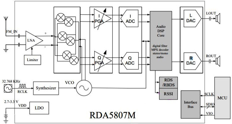
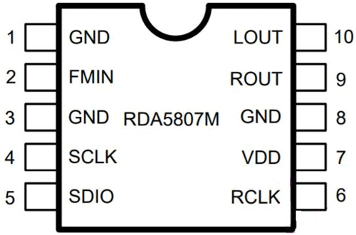
It has digital low-IF architecture and integrates a low noise amplifier (LNA), which supports the FM broadcast band (50 to 115 MHz), a programmable gain control(PGA), a high-resolution analog-to-digital converter, and a high fidelity digital-to-analog converters (DACs). The limiter prevents overloading and limits the number of intermodulation products created by adjacent channels. The PGA amplifies the mixer output signal and then digitized with ADCs. The DSP core manages the channel selection, FM demodulation, stereo MPX decoder, and output audio signal. The RDA5807 pinout diagram for the IC is given below.
The module works on the power supply of 1.8 – 3.3V. When coming to rest and control interface selected, the module resets itself when VIO is Power up, and also supports soft reset by the trigger of bit1 from 0 to 1 of 02H address. The module uses I2C communication to communicate with the MCU, and the interface begins with starts condition, a command byte, and data bytes. The RDA5807 has 13 16-bit registers, each performing a particular function. The register addresses start with 00H, which is allotted to chip ID and ends with 0FH. In all 13 registers, some bits are reserved while some are R/W. Each register performs tasks like varying volume, changing channels, etc depending upon the bits assigned to them.
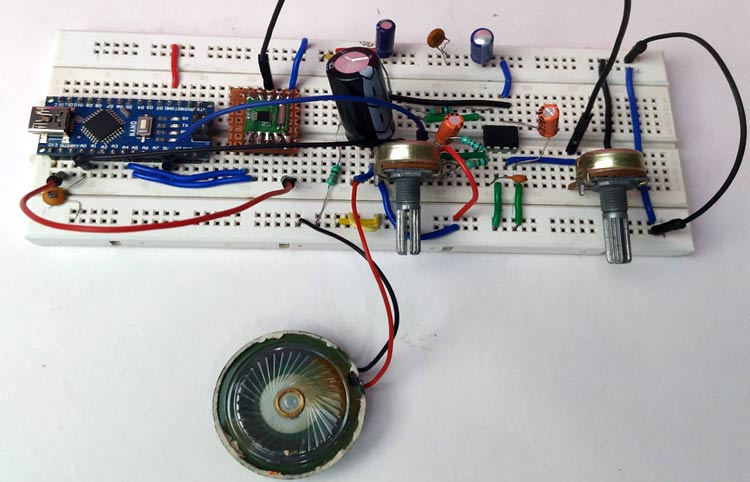
We cannot directly use the module when connecting it to a circuit as the pins are closed by. So, I used a perf board and some male pins and soldered the module’s each pin to each male pin as shown in the pic below.

Audio Amplifier
An audio amplifier is an electronic device, which amplifies low-power electronic audio signals to a level where it is high enough for driving loudspeakers or headphones. We have built a simple audio amplifier using LM386, the circuit for the same is shown below and you can also check the link to learn more about this circuit, also check other audio amplifier circuits.
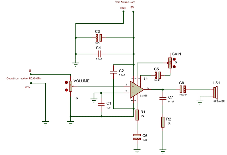
Arduino FM Receiver Circuit Diagram
We used two potentiometers for tuning the FM band and controlling the volume of the audio amplifier. To change the volume you can either vary the pot, which is connected in between 1 and 8th pin of LM386 or the pot, which is connected at pin 3 of the LM386. The below pic shows the complete circuit diagram for Arduino FM Radio.

I did little changes in the amplifier. Instead of using two potentiometers in the amplifier, I used only one. I interchanged the pot, which is used to change the Gain, with a resistor. So now our project has two potentiometers one to tune, and one to change the volume. The potentiometer, which is used to tune the channel is connected with the Arduino nano. The center pin of the pot is connected to the A0 pin of the Arduino nano, and either of the remaining two pins is connected to the 5V and the other is connected to the GND. Another pot is used to control the volume of the radio and is connected as shown in the above fig.
The pin A4 and A5 of the Arduino are connected to SDA and SCL pin of the RDA5807M. keep in mind that the receiver module works only on 3.3V. So, connect the 3v3 pin of the Nano to the VCC pin of the receiver module. Once the connections were made my set-up looked like this
Arduino FM Radio Code Explanation
The code will initialize the receiver module and then sets the channel with the preset frequency. When the value read by the nano at the A0 pin changes (by changing pot) the frequency changes which in turn changes the channel. The full code is given at the end of the page.
We begin our program by adding the required wire library for communicating with RDA5807. Then, in the variable “channel” we set the value of the channel. Whenever the radio starts it will get tuned to this channel automatically.
#include <Wire.h>
uint16_t channel = 187;
Next, we will load bytes to each register on our RDA5807 IC to set our initial configuration. At this point, we are resetting the receiver.
uint8_t boot_config[] = {
  /* register 0x02 */
  0b11000001,
  0b00000011,
  /* register 0x03 */
  0b00000000,
  0b00000000,
  /* register 0x04 */
  0b00001010,
  0b00000000,
  /* register 0x05 */
  0b10001000,
  0b00001111,
  /* register 0x06 */
  0b00000000,
  0b00000000,
  /* register 0x07 */
  0b01000010,
  0b00000010,
};
After we reset the device, we can tune the device. For tunning the channel we only need to program the first 4 bytes. This part of the code will change the channel to the desired frequency. In I2C at first, we begin the transmission, Write or read the data and then end the transmission. In this receiver IC, we don’t have to specify the address as the datasheet clearly says that the I2C interface has a fixed start register i.e. 0x02h for a write operation, and 0x0Ah for a read operation.
uint8_t tune_config[] = {
  /* register 0x02 */
  0b11000000,
   0b00000001,
   /* register 0x03 */
   (channel >> 2),
   ((channel & 0b11) << 6 ) | 0b00010000
};
In the setup, we initializing the boot configuration (reset) and then tuning to a channel by writing tuning configuration bytes to the RDA5807M.
void setup()
{
  Serial.begin(9600);
  pinMode(A0,INPUT);
  /* Conect to RDA5807M FM Tuner: */
  Wire.begin();
  Wire.beginTransmission(RDA5807M_ADDRESS);
  Wire.write(boot_config, BOOT_CONFIG_LEN);
  Wire.endTransmission();
  Wire.beginTransmission(RDA5807M_ADDRESS);
  Wire.write(tune_config, TUNE_CONFIG_LEN);
  Wire.endTransmission();
}
When using pot for tuning to a frequency, I had faced a problem. The values which are read by the A0 pin are not constant. There is a noise clubbed with the desired value. I used a 0.1uF ceramic capacitor connected between A0, and GND, though the noise got minimized, it is not up to the desired level. So, I had to do some changes to the code. At first, I noted down the readings which are affected by the noise. I found out that the maximum value of the noise is 10. So I wrote the program in such a way that, it will only consider the new value if the difference between the new value and the old value of that same pin is greater than 10 and then tunes to the desired channel.
void loop()
{
  int channel1 =187 ,avg=0, newA;
  static int oldA = 0;
  int result = 0;
  newA = analogRead(A0);
  if ((newA - oldA) > 10 || (oldA - newA) > 10){
   Serial.println(newA);
  if(newA!= oldA){
     channel = channel1+(newA/10);
    myChangeChannel(channel);
    oldA=newA;
  }
}
}//loop end
This function is used to set the bytes of the tune_config array and then transmits the data to the RDA5807M IC using the I2C protocol.
void myChangeChannel(int channel){ /* void if nothing is returned else int */
   tune_config[2] = (channel >> 2);
   tune_config[3] = ((channel & 0b11) << 6 ) | 0b00010000;
      Wire.begin();
      Wire.beginTransmission(RDA5807M_ADDRESS);
      Wire.write(tune_config, TUNE_CONFIG_LEN);
      Wire.endTransmission();
  }
Working of Arduino FM Radio
When the module is powered up, our code resets the RDA5807-M IC and sets it to a channel of the user desired (Note: this frequency is taken as the base frequency upon which the frequency will be incremented). By changing the potentiometer (connected to A0), the values read by the Arduino Nano changes. If the difference between the new and old value is greater than 10, our code will consider this new value. The channel is changed depending upon the change in the new value from the old value. Increasing or decreasing the volume depends on the potentiometer, which is connected in between the pin 3 and GND.
At the end of the construction and coding, you will be having your own FM Radio. The complete working of the FM Radio can be found in the video linked at the bottom of this page. Hope you enjoyed the project and learned something useful. If you have any questions in getting this project to work you can leave them in the comment section or use our forums for other technical help.
Complete Project Code
#include <Wire.h>

    /* Select the frequency we want to tune to by way

     * of selecting the channel for the desired frequency

     */

uint16_t channel = 187;

    /*

     * assuming band starts at 87.0MHz (per settings below)

     * and channel spacing of 100kHz (0.1MHz) (per settings below)

     * then channel can be derived as follows:

     *

     * channel = (<desired freq in MHz> - 87.0) / 0.1

     *

     * which is the same as:

     * <10 x desired freq in MHz> - 870

     */

#define RDA5807M_ADDRESS  0b0010000 // 0x10

#define BOOT_CONFIG_LEN 12

#define TUNE_CONFIG_LEN 4

/*

 *  These bytes set our initial configuration

 *  We don't bother to tune to a channel at this stage.

 *  But instead initiate a reset.

 */

uint8_t boot_config[] = {

  /* register 0x02 */

  0b11000001,

    /*

     * DHIZ audio output high-z disable

     * 1 = normal operation

     *

     * DMUTE mute disable

     * 1 = normal operation

     *

     * MONO mono select

     * 0 = stereo

     *

     * BASS bass boost

     * 0 = disabled

     *

     * RCLK NON-CALIBRATE MODE

     * 0 = RCLK is always supplied

     *

     * RCLK DIRECT INPUT MODE

     * 0 = ??? not certain what this does

     *

     * SEEKUP

     * 0 = seek in down direction

     *

     * SEEK

     * 0 = disable / stop seek (i.e. don't seek)

     */

  0b00000011,

    /*

     * SKMODE seek mode:

     * 0 = wrap at upper or lower band limit and contiue seeking

     *

     * CLK_MODE clock mode

     *  000 = 32.768kHZ clock rate (match the watch cystal on the module)

     *

     * RDS_EN radio data system enable

     * 0 = disable radio data system

     *

     * NEW_METHOD use new demodulate method for improved sensitivity

     * 0 = presumably disabled

     *

     * SOFT_RESET

     * 1 = perform a reset

     *

     * ENABLE power up enable:

     * 1 = enabled

     */

  /* register 0x03 */

    /* Don't bother to tune to a channel at this stage*/

  0b00000000,

    /*

     * CHAN channel select 8 most significant bits of 10 in total

     * 0000 0000 = don't boher to program a channel at this time

     */

  0b00000000,

    /*

     * CHAN two least significant bits of 10 in total

     * 00 = don't bother to program a channel at this time

     *

     * DIRECT MODE used only when test

     * 0 = presumably disabled

     *

     * TUNE commence tune operation

     * 0 = disable (i.e. don't tune to selected channel)

     *

     * BAND band select

     * 00 = select the 87-108MHz band

     *

     * SPACE channel spacing

     * 00 = select spacing of 100kHz between channels

     */

  /* register 0x04 */

  0b00001010,

    /*

     * RESERVED 15

     * 0

     *

     * PRESUMABLY RESERVED 14

     * 0

     *

     * RESERVED 13:12

     * 00

     *

     * DE de-emphasis:

     * 1 = 50us de-emphasis as used in Australia

     *

     * RESERVED

     * 0

     *

     * SOFTMUTE_EN

     * 1 = soft mute enabled

     *

     * AFCD AFC disable

     * 0 = AFC enabled

     */

  0b00000000,

    /*

     *  Bits 7-0 are not specified, so assume all 0's

     * 0000 0000

     */

  /* register 0x05 */

  0b10001000,

    /*

     * INT_MODE

     * 1 = interrupt last until read reg 0x0C

     *

     * RESERVED 14:12

     * 000

     *

     * SEEKTH seek signal to noise ratio threshold

     * 1000 = suggested default

     */

  0b00001111,

    /*

     * PRESUMABLY RESERVED 7:6

     * 00

     *

     * RESERVED 5:4

     * 00

     *

     * VOLUME

     * 1111 = loudest volume

     */

  /* register 0x06 */

  0b00000000,

    /*

     * RESERVED 15

     * 0

     *

     * OPEN_MODE open reserved registers mode

     * 00 = suggested default

     *

     * Bits 12:8 are not specified, so assume all 0's

     * 00000

     */

  0b00000000,

    /*

     *  Bits 7:0 are not specified, so assume all 0's

     *  00000000

     */

  /* register 0x07 */

  0b01000010,

    /*

     *  RESERVED 15

     * 0

     *

     * TH_SOFRBLEND threshhold for noise soft blend setting

     * 10000 = using default value

     *

     * 65M_50M MODE

     * 1 = only applies to BAND setting of 0b11, so could probably use 0 here too

     *

     * RESERVED 8

     * 0

     */

  0b00000010,

    /*

     *  SEEK_TH_OLD seek threshold for old seek mode

     * 000000

     *

     * SOFTBLEND_EN soft blend enable

     * 1 = using default value

     *

     * FREQ_MODE

     * 0 = using defualt value

     */

};

/* After reset, we can tune the device

 * We only need program the first 4 bytes in order to do this

 */

uint8_t tune_config[] = {

  /* register 0x02 */

  0b11000000,

    /*

     * DHIZ audio output high-z disable

     * 1 = normal operation

     *

     * DMUTE mute disable

     * 1 = normal operation

     *

     * MONO mono select

     * 0 = mono

     *

     * BASS bass boost

     * 0 = disabled

     *

     * RCLK NON-CALIBRATE MODE

     * 0 = RCLK is always supplied

     *

     * RCLK DIRECT INPUT MODE

     * 0 = ??? not certain what this does

     *

     * SEEKUP

     * 0 = seek in down direction

     *

     * SEEK

     * 0 = disable / stop seek (i.e. don't seek)

     */

   0b00000001,

    /*

     * SKMODE seek mode:

     * 0 = wrap at upper or lower band limit and contiue seeking

     *

     * CLK_MODE clock mode

     * 000 = 32.768kHZ clock rate (match the watch cystal on the module)

     *

     * RDS_EN radio data system enable

     * 0 = disable radio data system

     *

     * NEW_METHOD use new demodulate method for improved sensitivity

     * 0 = presumably disabled

     *

     * SOFT_RESET

     * 0 = don't reset this time around

     *

     * ENABLE power up enable:

     * 1 = enabled

     */

   /* register 0x03 */

   /* Here's where we set the frequency we want to tune to */

   (channel >> 2),

    /* CHAN channel select 8 most significant bits of 10 in total   */

   ((channel & 0b11) << 6 ) | 0b00010000

    /*

     *  CHAN two least significant bits of 10 in total

     *

     * DIRECT MODE used only when test

     * 0 = presumably disabled

     *

     * TUNE commence tune operation

     * 1 = enable (i.e. tune to selected channel)

     *

     * BAND band select

     * 00 = select the 87-108MHz band

     *

     * SPACE channel spacing

     * 00 = select spacing of 100kHz between channels

     */

};

void setup()

{

  Serial.begin(9600);

  pinMode(A0,INPUT);

  Wire.begin();

  Wire.beginTransmission(RDA5807M_ADDRESS);

  Wire.write(boot_config, BOOT_CONFIG_LEN);

  Wire.endTransmission();

  Wire.beginTransmission(RDA5807M_ADDRESS);

  Wire.write(tune_config, TUNE_CONFIG_LEN);

  Wire.endTransmission();

}//setup end

void loop()

{

  int channel1 =90,newA;

  static int oldA = 0; // set the oldA as HIGH

  int result = 0;

  newA = analogRead(A0);

  if ((newA - oldA) > 10 || (oldA - newA) > 10){

    Serial.println(newA);

    if(newA!= oldA){

      channel = channel1+(newA/10);

      myChangeChannel(channel);

      oldA=newA;

      }

}

  uint16_t frequency = channel+870;

  uint16_t num1 = (frequency / 1000) % 10;

  uint16_t num2 = (frequency / 100) % 10;

  uint16_t num3 = (frequency / 10) % 10;

  uint16_t num4 = frequency % 10;

  Serial.print(num1);

  Serial.print(num2);

  Serial.print(num3);

  Serial.print(num4);

  Serial.print("--");

  Serial.println(channel+870);

}//loop end

/*

 * Function to change channel on radio RDA5807

 * Example: channel = 191

 */

void myChangeChannel(int channel){ /* void if nothing is returned else int */

  /*

   * first write new channel to tune_config massive

   */

   tune_config[2] = (channel >> 2);

   tune_config[3] = ((channel & 0b11) << 6 ) | 0b00010000;

      Wire.begin();

      Wire.beginTransmission(RDA5807M_ADDRESS);

      Wire.write(tune_config, TUNE_CONFIG_LEN);

      Wire.endTransmission();

  }
Comments
Is it possible to detect noise or audio with RDA5807.
I mean do we get any register value change, when on a particular channel, is there noise or actual audio?
Is it possible to get a complete schematic diagram of the radio circuit? Can I substitute the RDA5807FP in place of the RDA5807M?
Hi, only the above given connection diagram is available. Yes you can use RDA5807M instead.
I'm having a hard time following the breadboard diagram as the picture isn't very clear. Can you list what pins on the RDA5807M go to which pins on the Arduino Nano? I'm also having trouble reading the value of the one resistor that is coming out of the Arduino. In advance, thank you for the help.
Hi, the connections are as follows
RDA5807M Arduino Nano
VCC 3.3V
SCL A5
SDA A4
GND GND
Connect either Rout or Lout to the amplifier input. Amlifier schematics(with component values) can be found on the top. And to the ANT pin, connect an antenna or a wire with the appropriate length.
Thanks for the quick response. The connections for the amplifier portion are not important as I have a good schematic for it. I assumed that SCL and SDA went to A5 and A4. But how is the potentiometer (for tuning) connected to Arduino? It appears that pins 1 and 3 go to 3.3V and ground. However pin 2 goes to Arduino. But I can't tell which pin it is connected to.
Again, thanks for the help.
Pin 2(center pin) is connected to the A0 pin of the Arduino.
Hello, I am in a process of finding tutorial to build a radio by myself. This tutorial seems to be the best, as it is relatively simple and well-explained. So, I would like to ask does it really work? I mean, what's the sound quality? Are you satisfied with the outcome of this project?
instead of using a speaker as output, can you use a bluetooth transmitter, if so, how would i wire toh chip to transmitter?

Hi,
compliments for your work !!
A little caveat:
the I2C voltage level accepted by RDA5807 is 3.3V maximum ..
The Arduino Nano is a 5V device, then you can damage the receiver chip !!
it is better to place a level shifter on the SDA and SCL pin. (2 mosfet and 4 resistors).
best regards.
Mauro IK1WVQ