
One of the cool projects I always wanted to build is an FM transmitter with a good range. I have always been fascinated by some of the applications of the transmitter, especially when I was younger and, like everyone else, spent most of my time imagining how cool it would be to have some of the equipment and devices used in spy movies. So recently, while going over one of my home automation/security projects using the Raspberry Pi and the motion library, I felt it would be cool to add sound to the project and listen live, so aside from the video feedback being supplied by the Pi, I can also get audio feedback from the area being monitored. So during the ideation session to implement this Raspberry pi surveillance system, this FM transmitter idea came back to me, and while it won’t allow me to listen remotely (a distance beyond 10km), it will at least allow me keep an “ear” on things when around the house, and after building it I would have achieved some of the goals the younger me had. So I finally found the strength to build it a few days back, and in today’s tutorial, I will be sharing how you can build your own FM transmitter circuit and believe me, it works perfectly. If you are new to building an FM Circuit project, you can have this tutorial What is Amplitude Modulation? a complete guide. You can also have a look at this project to learn how to build a smart home automation system using the ESP32.
At this point, it is important to state that this is being done only for experimental and learning purposes, as the laws of certain countries prohibit unauthorised broadcasting. It is thus important to keep the FM transmitter at a low range and ensure it is built within the frame of the laws of your country and does not cause a nuisance to the public. I take no holdings for any mishaps. Discover how to transform your Raspberry Pi into a functional FM radio transmitter with a simple setup. We have also done hands-on projects for enthusiasts and professionals on how Edge AI-Powered Surveillance enhances with intelligent threat detection capabilities.
Table of Contents
How Does an FM Transmitter Circuit Work?
An FM transmitter is a device that uses the principles of frequency modulation to broadcast sound supplied at its input. Typical FM transmitter designs usually follow the block diagram below;

The FM transmitter module uses frequency modulation principles to broadcast audio signals wirelessly. Understanding the FM transmitter block diagram is essential before building the circuit. The FM (Frequency Modulation) technique varies the carrier frequency in proportion to the audio signal amplitude, allowing clear audio transmission without significant interference.
The signal strength of audio inputs into the transmitter is usually low; therefore, an amplifier is usually built to bring the signal level up. Based on the desired frequency for transmission (which is usually between the FM frequency band, 88MHz to 108MHz), the carrier frequency is generated using an oscillator circuit and mixed with an audio signal to create the modulated signal. The modulated signal is then passed through a power amplifier at the transmission stage to create a low impedance which is matched with the antenna. When designing an FM audio transmitter, the audio input signals are very weak (millivolt range).
FM Transmitter Block Diagram Components:
The FM transmitter schematic diagram consists of four main stages:
- The audio preamplifier stage: that amplifies a weak microphone signal to workable levels.
- The Oscillator circuit stage: which generates the carrier frequency (88-108 MHz).
- The Modulator stage: where you combine the modulated audio signal and carrier frequency together.
- The RF amplifier stage & Antenna stage: the RF amplifier stage will amplify both modulated signals and provide an interference signal through the antenna.
Components Required for FM Transmitter Circuit Board
Building a reliable FM transmitter circuit board requires careful component selection. The following components are required to build this FM Transmitter Project:
- 2n2222 NPN Transistor x2
- Condenser mic/ audio jack or any other Audio Input part
- 100nf Ceramic capacitor x1
- 10nf ceramic capacitor x1
- 4 pf ceramic capacitor x1
- 100 ohms resistor x1
- 10k resistor x 3
- 1k resistor x 1
- 100k resistor x1
- 1M resistor x1
- Variable Capacitor 20pf
- Gauge 18 - 22 copper wire
- 9v battery
- 9V battery Cap
Most of these components can be salvaged from old parts.
FM Transmitter Circuit Diagram with Detailed Explanation
Connect the components as shown in the Simple FM transmitter circuit below.

This is how this simple FM transmitter circuit looks on a breadboard
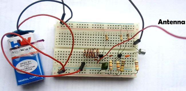
Follow this detailed procedure to build your FM transmitter circuit board on a breadboard or PCB
The audio output signal from the microphone is usually small; the first transistor thus performs the job of amplifying that signal to a level good enough for transmission. After amplification as described earlier, the next stage of the FM transmitter is modulation. At this stage, the amplified audio signal is then mixed with the carrier frequency at which the signal is to be transmitted. This carrier frequency can be varied using the 20pF variable capacitor connected with the inductor, and the typical frequency band of this particular design is between the 88MHz to 108MHz and since there is no visual output to recognize the exact frequency at which the transmitter is working, you will need to adjust your FM receiver radio within the range of the frequencies mentioned to get the frequency at which the transmitter is transmitting. After modulating the Audio signal with the carrier frequency, the signal is then sent out through the antenna.
The air core inductor is made by winding 8 to 10 turns of 18 – 22 gauge wire around a ¼ inch former, which can be represented by a pencil. The values of components used for these tutorials are not stringent, and for learning purposes, you can play around with the resistor and capacitor values to optimise the performance of the transmitter.
Aside from the uses mentioned above, FM transmitters, along with this design, can be used to create things like a baby monitor, an Address system for a school, etc. DO ENSURE to check the laws of your location before building any of those useful things.
That’s it for this tutorial, folks, another childhood dream accomplished!
Comparing FM Transmitter Circuit Designs
| Design Type | Complexity | Range | Audio Quality | Best Application |
|---|---|---|---|---|
| Single Transistor | Very Simple | 10-50m | Low | Beginner learning |
| Two Transistor (This Design) | Moderate | 50-300m | Good | Home projects |
| IC-Based (BA1404) | Simple | 100-500m | Excellent | Stereo broadcasting |
| PLL Synthesized | Advanced | 500m-2km | Excellent | Professional applications |
| Multi-Stage Amplified | Expert | 2km+ | Excellent | Requires license |
Technical Specifications
- Operating Frequency: 88-108 MHz (VHF FM Band)
- Frequency Stability: ±50 kHz (depends on component quality and temperature)
- Output Power: Approximately 50-100 mW (estimated)
- Current Consumption: 15-25 mA at 9V DC
- Audio Frequency Response: 300 Hz - 3.5 kHz (speech optimised)
- Modulation Index: Adjustable via input level (optimal: 2.5-3.0)
- Antenna Impedance: Approximately 50-75 Ω (monopole antenna)
- Signal-to-Noise Ratio: >40 dB at close range
- Harmonic Distortion: <5% with proper biasing
- Operating Temperature Range: 0°C to 50°C
- Battery Life: 20-30 hours with standard 9V alkaline battery (400-500 mAh)
Troubleshooting Common FM Transmitter Issues
| Problem | Possible Cause | Solution |
|---|---|---|
| No transmission detected | Oscillator not functioning, incorrect inductor value | Check inductor connections, verify transistor is not damaged, ensure LC circuit resonance |
| Very weak signal | Poor antenna, low battery, incorrect component values | Replace battery, extend antenna length, check all resistor values |
| Distorted audio | Over-modulation, excessive input signal | Reduce microphone gain, add series resistor to audio input |
| Frequency drift | Temperature variations, loose connections | Use temperature-stable components, and secure all connections with solder |
| Battery drains quickly | Excessive current draw, short circuit | Verify all component values, check for solder bridges, measure current draw (should be 10-20mA) |
Advanced FM Transmitter Modifications
For experienced electronics enthusiasts looking to enhance this FM transmitter project, consider these advanced modifications
» 1. Frequency Synthesiser
Use a PLL (Phase-Locked Loop) IC, such as the MC145151, to replace the variable capacitor of the transmitter for stable, digitally controlled operation across a range of temperatures to keep the transmitter air, as it has over 300 useful frequency bands.
» 2. Power Amplifier Stage
Adding the third transistor (a 2N3866 RF transistor) as a Class-C amplifier could increase the range the transmitter operates as far as 1KM+. Remember directional couplers or RF filtering, and, most importantly, heat sinking.
» 3. Stereo FM Encoding.
A 38KHz stereo encoder IC (like the BA1404 or BH1417 can be designed to have stereo sound from an audio signal broadcast on an FM signal with left/right channel separation.
» 4. Audio Compressor/Limiter
You can use an automatic gain control circuit (AGC) to control the audio signal to help prevent over-modulating the FM signal, and then have more stable audio levels regardless of the signal input level strength before the preamplifier.
Conclusion: Your Journey into RF Electronics
The process of building this FM transmitter circuit is more than just putting the components together—it's a practical introduction to radio frequency electronics, modulation theory, and the principles of wireless communication. This simple FM transmitter circuit illustrates how relatively few components can create functioning RF communication when properly designed. The experience gained in wiring this FM transmitter project is a useful step towards understanding other wireless systems, such as Wi-Fi, Bluetooth, cellular, and software-defined radio (SDR).
Whether you are going to use this FM transmitter module to monitor audio from a home surveillance perspective, as a baby monitor system, or just looking to explore RF circuit design, please remember that you should always carry out your experimentation in a responsible way that considers ethics, local laws, and technical best practices. The Circuit Digest engineers have done a diverse range of Electronic Circuits, Home Automation Projects and IoT projects.
Frequently Asked Questions on the Simple FM Transmitter Circuit
⇥ 1. What might prevent me from hearing the signal from my FM transmitter on the radio?
The usual suspects are: a non-operating oscillator (which could be tested by checking transistor connections or inductor wires), LC tank values that prevent oscillation, a dead battery (usually must have a >7V battery), an inductor not wound correctly (verify winding 8-10 times on ¼ inch diameter), or an antenna not connected. You can track down issues with your transmitter by using a multimeter to check DC voltages as well as possible values at each of the transistor terminals.
⇥ 2. How can I make my FM transmitter have a longer range?
You might be able to attain a longer range by: extending antenna to be 70cm (which is a full wavelength at 100MHz), increasing transmitter height and height of the antenna, using high quality power source like 9V battery or regulated power, adding third-stage RF power amplifier (which could be accomplished with 2N3866 transistor) reducing total cable losses through the use of 50Ω coaxial feeds, and ensuring that are maintaining correct impedance matching between the oscillator and antenna stage.
⇥ 3. What is the frequency of this FM transmitter?
The circuit works over the 88-108 MHz FM broadcast range, adjustable through a 20pF variable capacitor. Precise frequency is determined by inductor value and capacitance. To determine the operating frequency, slowly sweep your FM receiver across the whole band while making adjustments to the variable capacitor until you hear the audio that's being transmitted. Set the calibration point for repeatable tuning.
⇥ 4. Is it possible to transmit music from my phone with this FM transmitter?
Yes, hook up the phone's 3.5mm audio output to the transmitter's input through a suitable cable (use an audio jack instead of the microphone). Set phone volume to 50-70% to avoid over-modulation and distortion. This provides wireless streaming to any FM radio, perfect for cars that do not have Bluetooth or an aux input, but audio quality will not be comparable to commercial FM transmitters.
⇥ 5. What is the duration a 9V battery will power the FM transmitter?
An alkaline 9V battery (400-500mAh capacity) of a standard will provide 20-30 hours of continuous performance, due to the circuit current draw (15-25 mA). A rechargeable 9V NiMH (200-300mAh) will provide 10-15 hours. In a permanent installation, a regulated 9V DC wall adapter or a 6x AA battery pack are a good option, since they will provide longer-lasting power and more stable voltage during load.
⇥ 6. Why is my FM transmitter's sound distorted?
Audio distortion is caused by over-modulation (input signal too high), improper bias voltages on the transistor amplifier, excessive microphone gain, or low battery voltage that triggers clipping. Correct by: lowering the input signal level, adding a series resistor (10kΩ-47kΩ) to the audio input, verifying transistor bias voltages are specified, replacing a weak battery, and using correct decoupling capacitor values.
⇥ 7. Do I need any special tools to build this FM transmitter?
There are a few basic tools required for this project, including a soldering iron and ring solder, or you can use a breadboard instead to accommodate the experimentation, wire cutters and wire strippers, a small screwdriver to trim the variable capacitor, a digital multimeter to check voltages, and an FM radio receiver to check the tuning. Optional, but helpful things you might want: an oscilloscope to measure waveforms; a helping hands tool; and a pencil or drill bit to form the inductor winding.
DIY Experiments with FM Transmitters and Receivers
We’ve previously implemented FM communication in various projects; you can explore them through the links below.

Simple DIY FM Receiver Circuits on the Internet - Do they Really Work?
So in this tutorial, we did just that by building a few circuits on a piece of perf board and testing each circuit to see if it was working and what can be done to improve this, and in the end, we will let you know all the details. Building a simple FM receiver circuit from scratch can be both educational and rewarding.

In this project, you will learn how an FM Transmitter Works and how you can build your own with subtle components. We are adapting the circuit given by Tony Van Roon, given in the book “Circuits for Hobbyists” (Page 75). This is an excellent book to start with if you want to do some tinkering with electronics.

How to Build a Raspberry Pi FM Transmitter
Almost every electronics engineer tries to build an FM Transmitter using a coil and other components, but it's a tedious task to properly tune it. Surprisingly enough, with the help of Raspberry Pi, it should hardly take less than half an hour to set up your own FM broadcasting station and get on air within a local area.
Comments
It doesn't get work please give suggestion

Wish to have my radio station. Thanks for your l information on this matter